
Abstract
Abstract
The hybrid process of selective noncatalytic reduction (SNCR) followed by selective catalytic reduction (SCR) is an up-to-date nitrogen oxides control technique and can achieve a high efficiency (60%–95%) with moderate cost. The SNCR/SCR hybridization was investigated through experimentation on a 100 MW, coal-fired utility boiler in China. The baseline nitrogen oxides emission of the hybrid urea-based SNCR/SCR system was 170 ppm at 6% O2 controlled by coal reburning technology. The hybrid SNCR/SCR system including only 89 m3 catalysts could control NO emission under 25 ppm with ammonia slip <4 ppm at 300–430 tons/h of boiler load. Total NO reduction efficiency was generally about 85% and could be beyond 90%, in which SCR's efficiency was 50%–70% individually and SNCRs was about 60%–75%. NO emission decreased from about 65 to 15 ppm when the flow rate of 35% urea solution increased from 0.15 to 0.47 tons/h. At higher boiler load, more urea solution had to be injected and higher layer of the agent injectors had to come into operation to hit the same emission target. The superheated steam was injected with high speed into flue gases at the inlet of reversing chamber and it was effective on enhancing both the total quantities and the distribution of SNCR's ammonia residue, which was used as reducing agent of SCR. In general there was more NH3 where there was less NO at the inlet of catalysts and NO distribution was contrary to NH3 distribution in some way. NO and NH3 distribution at the outlet of catalysts was almost even compared with the inlet distribution. Average NH3 slip at the outlet increased with NH3 at the inlet and could be controlled below 4 ppm at 6% O2 in any case. The difference between average NH3 at the inlet and the outlet was smaller several times than the reduced NO by SCR catalysts. Some isocyanic acid (HNCO) as the product of urea solution thermohydrolysis might exist in the flue gas and it was hydrolyzed to NH3 quickly on SCR catalysts, which then reduced NO on the surface of SCR catalysts.
Introduction
Experimental Methods
The utility boiler: introduction
The utility boiler located in Beijing, China, was built in 1999 and came into commercial operation ever since. It was a coal-fired boiler with high pressure, natural circulation, dry bottom, and tangential fire method. The economical continuous rate was 410 tons (t)/h of steam and the maximum was 450 t/h. The crossing section was 9.98 × 9.98 m, and the height level of drum was 42.6 m. The operated coal was Shenhua bituminous coal and its properties are given in Table 1. Two ball mills and a pulverized coal bin were equipped. The superheaters were composed of primary superheater, platen superheater, and final superheater. There were two economizers and two tube airheaters in the down duct. Before SNCR/SCR application with low NOx combustion technology, coal reburning had been retrofitted to control triumphantly NOx emission below 170 ppm at 6% O2. The details on the boiler and its coal reburning retrofit are depicted in the paper by Yang et al. (2009).
Description of the hybrid SNCR/SCR system
To suffice the regulation that NOx emission of this boiler should be controlled under 49 ppm, a three-step strategy was chosen according to the factors that concern the limited space, in-situ conditions, technology feasibility, and costs. The three steps, respectively, were coal reburning, SNCR, and SCR. After successful reburning retrofit, SNCR was applied in succession and finally SCR. And their NOx emission goals were set, respectively, below 170 ppm, 98 ppm with <10 ppm ammonia slip, and 49 ppm with <5 ppm ammonia slip at 6% O2. The strategy was feasible according to in-situ conditions and very cost-efficient. Coal reburning retrofit cuts down NO baseline of the combined SNCR/SCR from 270 to 170 ppm. The down of NO baseline not only economized greatly the initial investment but also the operation cost of the hybrid system. Moreover, low NOx combustion technology brought out more uniform crossing-section distribution of the temperature and the gases concentration in the upper furnace than normal combustion burners. And this uniform distribution greatly favored NO reduction of the hybrid system.
The SNCR system involved urea dissolving, urea solution store, diluting, and injecting parts. The urea solution whose concentration was 35% from the two urea solution tanks was diluted online with water before flowing into the wall injectors. Each injector was equipped with a vapor-assisted atomizing nozzle whose outlet diameter was 8 mm. The atomizing vapor was superheated steam at 0.4 MPa and the size of atomized liquid particle was in the region of 0.2–0.3 mm with 25 m/s of the velocity. Four layers of the injectors (L1–L4) were originally designed to suffice the wide boiler load range of 210–450 t/h, as shown in Fig. 1. The arrangement details of the injectors are depicted in Fig. 2. Five injectors were installed in the frontwall and one injector in each sidewall at L4 layer. Five injectors were installed in each sidewall, two injectors in the frontwall and two injectors in the rearwall on each of the other layers. The four layers achieved well the emission goal (Yang et al., 2009) and SNCR retrofit was in triumph.

Schematic diagram of the utility boiler and SNCR/SCR system. SCR, selective catalytic reduction; SNCR, selective noncatalytic reduction.
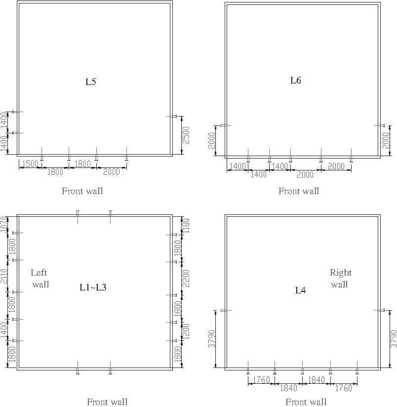
Arrangement of the injectors.
The SCR system involved 89 m3 catalysts, sootblowers, its controllers, and monitors, but not involved the reducing agent supply and injecting subsystems, which were shared with SNCR. The catalysis versus high gas hourly space velocity (GHSV) ≈ 4,400 h−1 was fixed in the high-dust region between the upper economizer and the upper airheater. The main component of SCR catalysts was V2O5/TiO2, which was effective in the temperature region of 573–673 K. The ammonia slip of SNCR was designed to be utilized as SCR reductant, and the injectors of SNCR were needed urgently to be rearranged to make more ammonia slip. Matching both the total quantities and the distribution of ammonia slip to NOx became the key to achieve good NOx reduction of SCR. Additional two layers of the injectors L5 and L6, shown in Figs. 1 and 2, were added on the furnace at 35 and 36.5 m levels and they injected urea solution into flue gas at lower temperature and increased more ammonia residue after SNCR. Although the special injectors had been arranged, the ammonia residue was excessive on the right side of the down duct and the gases' uniformity status was still not satisfied to SCR. To match the distribution of NH3 to NOx before the flue gas flowed into SCR catalysts, the steam was injected with high speed into the flue gas at the inlet of reversing chamber. The designed velocity of matching steam was 250 m/s. The five holes with 50 mm of inner diameter were mounted vertically in the right side shown in Fig. 1 and were used as the spouts of the matching steam, the source of which was superheated steam with 1.5 MPa and 630 K. The upper economizer was moved upward and its circular tubes were replaced with “H”-type gilled tube to shrink its bulk and to save the space for the catalysts, which were set underneath the upper economizer. The other benefits of “H” tubes were arousing the flue gas turbulence and helpful for the match of NH3 to NOx.
Measurement methods
Each debugging test of the hybrid SNCR/SCR lasted 3 h during which all monitor data were stable after the operation was carried out. In the debugging tests, the effects of injector layers, the matching steam, and urea solution flow rate on NO and NH3 were researched. The flue gas temperature in the furnace at the injection layers' level was measured by a Raytek Infrared Temperature Monitor with a precision of 1%. The flue gas could be sampled at 24 sites shown in Fig. 1 in the flue duct over and under the catalysts, and thus, the gas distribution across the down duct section (10 × 7 m) could be obtained. The gas data measured over the catalysts represented the data at the inlet of the catalysts and that under the catalysts represented the data at the outlet of the catalysts. Because a measurement hole at the inlet of the catalysts was jammed, the gases could not be sampled at 3 sites through the jammed hole and had to be sampled at the other 21 sites during the tests. The sampled gas flowed through a heated multiple pass, which kept the gas temperature at 453 K to avoid NH3 condensing and then came into the analyzer, Gasmet Dx4000. It analyzed NO and NH3 with 2% of the precision by an FTIR spectrometer. O2 was analyzed by a MRU4000 analyzer. The continuous rate, urea solution flow rate, and the other parameters were read from the unit DCS. The NO reduction efficiency of SNCR was calculated by the baseline NO emission (170 ppm at 6% O2) and the NO concentration at the inlet of the catalysts. And the efficiency of SCR was calculated by the NO concentrations at the inlet and outlet of the catalysts. The total efficiency was calculated by the NO at the outlet of the catalysts and the baseline NO.
Results and Discussion
L1–L4 injectors were specially designed for SNCR at 210–450 t/h of the boiler load. The flue gas temperatures at the level of L1–L4 in the furnace were 1,427, 1,398, 1,284, and 1,232 K at 410 t/h load and 1,372, 1,306, 1,240, and 1,150 K at 280 t/h load. The temperature at L1 and L2 were >1,300 K, which was too high to produce ammonia slip during the SNCR processes and the boiler operators found that ammonia slip was independent of L1 and L2 during SNCR running. As ammonia residue of SNCR was necessary for NO reduction of SCR in the hybrid system, the operation performance of L3–L6 was addressed and that of L1–L2 was omitted here. When the hybrid SNCR/SCR system was running, only one or two spouts were supplied for the matching steam to control the steam flow rate ( fs) and economize the operation cost. The effects of the matching steam were researched at 410 t/h load of the boiler with a mill running and the results are listed in Table 2, in which NSR meant N-agent/NO nitrogen stoichiometric ratio and the amount of [NH3]i and [NO]i was the average of 21 sampled points. As shown in Table 2, the average NO and NH3 concentration (at 6% O2) at the inlet of the catalysts, [NO]i and [NH3]i, were infected not only by the number of running spouts but also by the position of running spouts. As a whole, [NH3]i was increased and [NO]i was increased or decreased by the matching steam. Increased [NH3]i and decreased [NO]i were welcomed, as they favored SCR performance here. [NH3]i was more sensitive to the matching steam than [NO]i, and [NH3]i could be tripled by running the steam spouts, whereas [NO]i only increased several tens of percentage. As shown in Fig. 1, A–E spouts are located from bottom up at the inlet of the reversing chamber, and the flow rate of flue gas at different spout levels was different. In general, the flow rate in the middle part was larger and that on top was smaller. The result was that the matching steam of spout B or C would touch and stir more flue gas and achieve better matching effect, which was proved by the data in Table 2. Running two spouts meant more matching steam to stir the flue gas with greater momentum, which brought greater average of ammonia slip. As D spout running made [NO]i and [NH3]i worse instead of better, the test of E spout was omitted. B spout was selected as the optimal spout, taking into account the steam cost and the effects on [NO]i and [NH3]i.
Load = 410 tons/h, with a mill running; 400 kg/h of the flow rate of 35% urea solution; NSR = 1.59; L4 and L5 in operation.
NSR, N-agent/NO nitrogen stoichiometric ratio.
Figures 3 and 4 display NO and NH3 concentration distribution at the inlet section of the catalysts in tests 1 and 3. It should be mentioned that the region A in the graphs was blank because the gases could not be sampled at three sites through the jammed hole. Figures 3 and 4 show that there was more NH3 when there was less NO and NO distribution was contrary to NH3 distribution in some way. Without the matching steam in test 1, NO concentration was higher in regions B and D (>90 ppm) and lower in region C (<25 ppm). Although B spout changed [NO]i little, it changed NO distribution more significantly and made NO more even. Compared with NO in test 1, the area of region C decreased significantly and the high concentration of region D disappeared. Although region B was enlarged, the highest concentration (>110 ppm) reduced greatly. B spout running led [NH3]i to increase. The region F (NH3 > 15 ppm) was enlarged and the E region (NH3 > 15 ppm) shrinked. The NH3 in the region G of y = 3–5 m was not improved obviously, and thus, G was the region with low NH3 concentration in both tests 1 and 3.
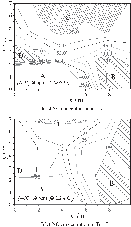
NO distribution at inlet of the catalysts in tests 1 and 3 (at 2.2% O2). A, no measured data; B, >90 ppm; C, <25 ppm; D, >90 ppm.

NH3 distribution at inlet of catalysts in tests 1 and 3 (at 2.2% O2). E, >15 ppm; F, >15 ppm; G, no obvious change region.
The NO reduction performances of the hybrid SNCR/SCR system at 300–430 t/h of boiler load are shown in Table 3, wherein [NO]o and [NH3]o mean the average NO and NH3 concentration (at 6% O2) at the outlet of the catalysts and fu means the flow rate of 35% urea solution. In many cases of the boiler running, the hybrid system could control NO emission under 25 ppm with ammonia slip <5 ppm. The upper injector layers came into operation when the boiler load increased. The needed fu increased from 0.22 to 0.45 t/h as the boiler load rose from 300 t/h, and 0.45 t/h of fu was enough in a wide load range of 350–430 t/h. When the hybrid system was out of operation, NO emission was usually under 170 ppm, which was considered as the baseline to calculate the total NO reduction efficiency in Table 3. It was generally about 85% and could be beyond 90%, in which SCR's portion by itself was 50%–70% and SNCR's portion was about 60%–75%. NO reduction of SNCR was greatly improved in the hybrid system. In the single urea–SNCR system, to avoid high ammonia slip, the urea solution was sprayed into the region where the temperature was over the optimum temperature and SNCR gained about 45% of NO reduction. In the hybrid system, without the ammonia slip limitation, more urea solution could be injected into the flue gas at the lower temperature, which resulted in dominating NO reduction reactions and weaker NH3 oxidation. The volume of SCR catalyst was reduced 20% or so by high-efficiency SNCR (Wendt et al., 2001) and was rightly suitable for onsite status (especially the space size). Here, SCR had a moderate NO reduction because of the downsized catalyst, which was only one layer versus high GHSV ≈ 4,400 h−1 at the boiler load of 410 t/h. The GHSV was much higher than the normal value of 2,000–3,500 h−1. As the catalyst size was small and the residence time was short, to meet 5 ppm of the ammonia slip limitation, the entrance NSR of SCR should be decreased. The concentration of NO and NH3 could be seen in Figs. 3 and 4. Each factor of the small-volume catalyst, high GHSV, low NSR, and the imperfect matching of NH3 to NO had an effect on debasing NO reduction of SCR.
NO and NH3 concentration distribution at the outlet of the catalysts in case 8 was drawn in Fig. 5. As there was 2.2% O2 in the flue gas, the contour lines were based on 2.2% of O2. NO concentration was in the range of 10–27 ppm and the average was 14 ppm. NO concentration in the left was a little lower than the average, whereas that in the right was higher, especially in the region of x = 6–9 m. Ammonia concentration was in the range of 1.0–8.9 ppm and the average was 4 ppm. Many NO was reduced by SNCR, although the catalyst volume was small; the entrance of low NH3 concentration could guarantee the low NH3 slip. There were seldom small sections where NH3 was >5 ppm at 6% O2. These sections located at the outer of the flue duct are shown as the shaded region in Fig. 5. Outlet NO and NH3 distribution was even in mass, compared with the inlet distribution.
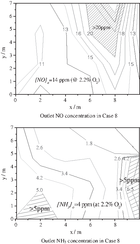
NO and NH3 distribution at outlet of catalysts in case 8 (at 2.2% O2).
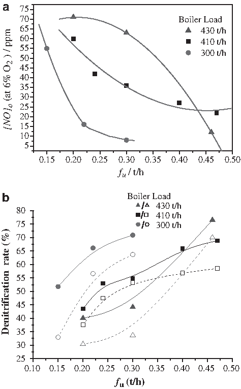
SNCR and SCR as the NOx control technologies using urea reductant performed better when more reductant was injected, as shown clearly in Fig. 6. NO emission decreased and the denitrification rate increased with increasing fu. More urea solution improved not only the denitrification of SNCR but also the denitrification of SCR, as shown in Fig. 6b. It was known that NO reduction increased with NSR when NSR was below 2.0 in the SNCR processes. More urea injection brought out more ammonia at the inlet of SCR, which increased denitrification of SCR because ammonia quantity is the most important operation factor of SCR's denitrification. The denitrification improvement became weaker with fu as fu reached a certain value. When the boiler load was 300 t/h, the fu increasing from 0.22 to 0.30 t/h (NSR from 1.20 to 1.64) only obtained another 8-ppm drop of NO emission. The increased urea showed poor enhancing effect on NO emission, and its contribution to NO reduction was weak and inefficient. The same phenomenon was captured at a load of 410 t/h. According to the curves in Fig. 6, it was not cost-effective that the emission target was set too low because more urea was utilized with low efficiency. The emission target should be set at 15, 35, and 40 ppm or so, respectively, at loads of 300, 410, and 430 t/h. In this case, the SNCR portion of the denitrification was over 60%, which could guarantee the hybrid SNCR/SCR system to be economical (Wendt et al., 2001).
Average ammonia concentrations at the outlet and inlet catalyst are described in Fig. 7, in which the capital letters near the symbol meant which mill was running. In general, [NH3]o could be controlled under 4 ppm at 6% O2 in any case and it increased with [NH3]i. Mill running condition impacted the temperature status and flow distribution in the furnace and down duct, which resulted in [NH3]o and [NH3]i changing. [NH3]o with A mill running was a little greater than that with B mill running at loads of 350 and 410 t/h, and [NH3]i with A mill running was a little smaller than that with B mill running at loads of 410 and 430 t/h. According to the data in Fig. 6, the difference between [NH3]o and [NH3]i was smaller several times than the reduced NO on SCR catalysts, which was calculated according to the data in Table 3. There were two reasons for this phenomenon. One was that measured NH3 concentration might be less than the actual concentration because the online precise measurement of ammonia in flue duct was considered commonly as a difficult problem and the novel method and equipment were being researched and developed (Dean, 2004; Gu et al., 2009). The other reason was that some isocyanic acid (HNCO) as the product of urea solution thermohydrolysis might exist in the flue gas and it could hydrolyze to NH3 on SCR catalysts (Fang and DaCosta, 2003; Piazzesi et al., 2006) and then reduce NO on the surface of catalysts. Thus, [NH3]i in the hybrid urea-based SNCR/SCR system need not be as much as that in pure SCR system.
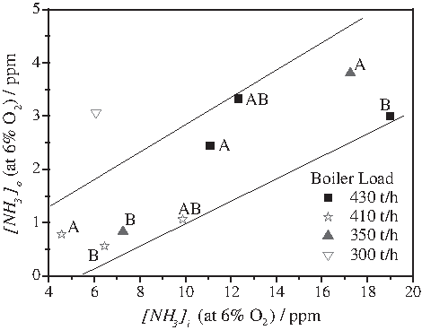
Average ammonia concentrations (at 6% O2; A or B means A or B mill running).
Summary
SNCR and SCR are widely applied to control NOx emission in thermal power plants and they have their own special advantages and shortcomings. SNCR/SCR hybridization technology combines them, eliminates their shortcomings, and has more advantages. Here, an SNCR/SCR hybrid system on a coal-fired boiler with 410 t/h economical continuous rate in China was researched, involving technology outline, NOx control performance, urea dosage, and ammonia distribution in the down duct.
Coal reburning had been retrofitted on the boiler and it controlled triumphantly NOx emission below 170 ppm at 6% O2, which was the baseline emission of the hybrid SNCR/SCR system with the target of 49 ppm at 6% O2. The hybrid system included SNCR subsystem (urea dissolving, urea solution store, solution online diluting, and injectors), SCR subsystem (89 m3 catalysts in down duct, sootblowers, and the matching steam), and the communal monitor and control system. Not only the catalyst volume was lessened but also the agent injector grids of SCR were omitted. Two special layers of SNCR injectors were added to supply enough ammonia residue after SNCR, which was used as SCR reductant and reduced NO on SCR catalysts. The special measures, matching steam and “H”-type economizer, were applied to make the flue gases uniform. These did great favor to the performance of the combined system.
The hybrid SNCR/SCR system could primely control NO emission under 25 ppm with ammonia slip <4 ppm at 300–430 t/h of boiler load. Total NO reduction efficiency was generally about 85% and could be beyond 90%, in which SCR's portion by itself was 50%–70% individually and SNCR was about 60%–75%. NO emission decreased from about 65 to 15 ppm with increasing fu and more urea solution had to be injected at higher boiler load to gain the same emission target. More urea brought out higher denitrification of not only SNCR but also SCR. Running one or two spouts of the matching steam could enhance both the total quantities and the distribution of ammonia slip, and the B spout was the optimal one of them. In general, there was more NH3 when there was less NO at the inlet of catalysts and NO distribution was contrary to NH3 distribution in some way. Outlet NO and NH3 distribution was even in mass, compared with the inlet distribution. For example, in case 8, NO concentration was in the range of 10–27 ppm and the average was 14 ppm. NH3 was in the range of 1.0–8.9 ppm and the average was 4 ppm. [NH3]o increased with [NH3]i and it could be controlled under 4 ppm at 6% O2 in any case. The difference between [NH3]o and [NH3]i was smaller several times than the reduced NO on SCR catalysts. One of the reasons was that some isocyanic acid (HNCO) as the product of urea solution thermohydrolysis might exist in the flue gas and it was hydrolyzed to NH3 on SCR catalysts before SCR reaction took place.
Footnotes
Acknowledgments
The authors acknowledge the financial support of National Hi-Tech Research and Development Program (863) of China (No. 2009AA05Z301) and the National Basic Research Program (973) of China (No. 2006CB200303). The authors also express their gratitude to the engineers and peoples who have worked for the SNCR/SCR project in Beijing Thermal Power Plant of Shenhua Guohua Co.
Author Disclosure Statement
No competing financial interests exist.