
Abstract
Abstract
Electro-Fenton (EF) oxidation of salicylic acid (SA) from an aqueous solution was studied in a continuous stirred tank reactor with the purpose of optimizing the process parameters on a laboratory scale. A laboratory-scale continuous-flow rectangular reactor, with a predetermined 3 L liquid volume of SA in the reactor, was used for this study. Electrolytic reactions carried out for 100 mg/L of SA solution, the parameters of catalyst concentration, pH, voltage, flow rate (residence time), and electrode spacing were varied. Electrolysis was carried out for a period of 10 h to optimize these parameters. A maximum of 70% oxidation was obtained at an initial Fe2+ concentration of 5 mg/L, pH of 2.5, voltage of 2.5 V, flow rate of 10 mL/min, and electrode spacing of 3 cm, after 10 h of electrolysis. Results obtained show the feasibility of this continuous EF process for the oxidation of SA.
Introduction
S
Recently, much attention has been paid to separate the source of the refractory or toxic effluent and treat it by advanced oxidation processes (AOPs) (Mohamed et al., 2009). Recently, many studies have been concentrated on the possibility to improve an economic aspect of these AOPs. Among AOPs, the Fenton process procured great attention in recent years (Balci et al., 2009). The major reaction mechanism of the Fenton process can be described by means of the following reactions [Eqs. (1)–(5)] (Pignatello et al., 2006):
The main drawbacks of the Fenton process are the use of a large quantity of chemical reagents, large production of ferric hydroxide sludge, and very slow catalysis of the ferrous ion generation (Özcan et al., 2008a). The electrochemical technique is one of the promising schemes that has been currently applied to eliminate or lessen the disadvantages of AOPs (Anotai et al., 2006; Brillas et al., 2009; Nidheesh and Gandhimathi, 2012). The main advantages of electrochemical techniques over other AOPs are its low operating cost and high mineralization efficiency (Oturan, 2000; Oturan et al., 2001). The electro-Fenton (EF) process is one of such electrochemical approaches (Harrington and Pletcher, 1999).
In the EF process, hydroxyl radicals generate continuously in the electrolytic system by the reaction between externally added ferrous or ferric ions and in situ generated hydrogen peroxide. H2O2 can be electrogenerated by the reduction of dissolved oxygen and Fe2+ by the reduction of Fe3+ [Eqs. (6) and (7)] (Qiang et al., 2003). Simultaneous Fe2+ regeneration will occur at the cathode according to the following equations [Eqs. (3), (8), and (9)] (Oturan et al., 2010; Nidheesh et al., 2013).
However, a part of •OH is lost by its direct reaction with Fe2+ [Eq. (2)] and with H2O2 [Eq. (5)] (Buxton et al., 1988; Sun and Pignatello, 1993). The rate of the Fenton reaction [Eq. (2)] can also decay by the oxidation of Fe2+ in the medium with HO2• [Eq. (10)] (Kwan and Voelker, 2002), as well as at the anode from the reaction [Eq. (11)], when an undivided cell is used.
Cathode material has a major role in the efficiency of the EF process. A wide variety of electrode materials such as carbon felt electrodes (Sirés et al., 2007; Oturan et al., 2008), graphite (Zhang et al., 2008; Nidheesh and Gandhimathi, 2013a, 2013b) or gas diffusion (Boye et al., 2003), carbon sponge (Özcan et al., 2008a), and activated carbon fiber (Wang et al., 2008) have been used as electrodes in various EF studies. In this study, the effectiveness of graphite electrode on the percentage of SA oxidation was investigated.
Usually, most of the wastewater treatment applications are conducted in a continuous mode (Rosales et al., 2009). However, very few studies have been conducted in a continuous mode for EF studies. To the best of our knowledge, there is no application of continuous mode EF technology in the oxidation of SA. Therefore, this study is conducted to find the effect of continuous mode EF technology in the oxidation of SA. The experiments were carried out in a laboratory scale for the synthetically prepared SA solution. The percentage of oxidation was evaluated in view of various operational parameters such as catalyst concentrations, pH, voltage, flow rate, and distance between sacrificial electrodes.
Materials and Methods
Materials
All chemicals used were analytical grade. The 99.8% pure SA (C7H6O3) was purchased from Merck. FeSO4·7H2O (Merck) was used as the source of Fe2+ catalyst in EF studies. The Orion EA940 Ion analyzer (Thermo) was employed for pH measurements and, pH of the working solution was adjusted using H2SO4 (Merck). Graphite plates were purchased from Anabond Sainergy Fuel Cell India Private Ltd., Chennai, India. DC power supply (0–5 A and 0–30 V) was used as the source of direct current. SA oxidation was determined by ultraviolet–visible light spectrophotometer (Lambda 25; PerkinElmer) using a quartz cell of path length 1 cm at 298 nm wavelength.
Experimental procedure
Electrolysis of the SA solution was carried out in a 30 cm×15 cm single-compartment electrolytic flow cell of 3000 mL working volume (Fig. 1). The electrolyte was prepared by dissolving 100 mg/L SA and 5 mg/L Fe2+ in distilled water. The initial pH of the solution was adjusted with 2 N (normality) H2SO4. An inlet tank was provided to hold the untreated SA solution to be passed into the system and the influent was passed through a 1-cm-diameter pipe. A flow control valve was used to control the flow of water entering the reactor. The experimental setup is shown in Fig. 1. Electrolyses were performed with DC power supplies using graphite electrodes under controlled electrolysis conditions. Six graphite plates of geometric area 40 cm2 were used as anodes and cathodes. Anodes and cathodes were arranged vertically as well as parallel with equal interelectrode spacing. Oxygen was supplied to the bottom of the cathodes by three fish aerators. The treated SA solution was collected in an outlet tank. During the experiments, samples were drawn from the reactor at predetermined time intervals and analyzed in a UV visible spectroscope.
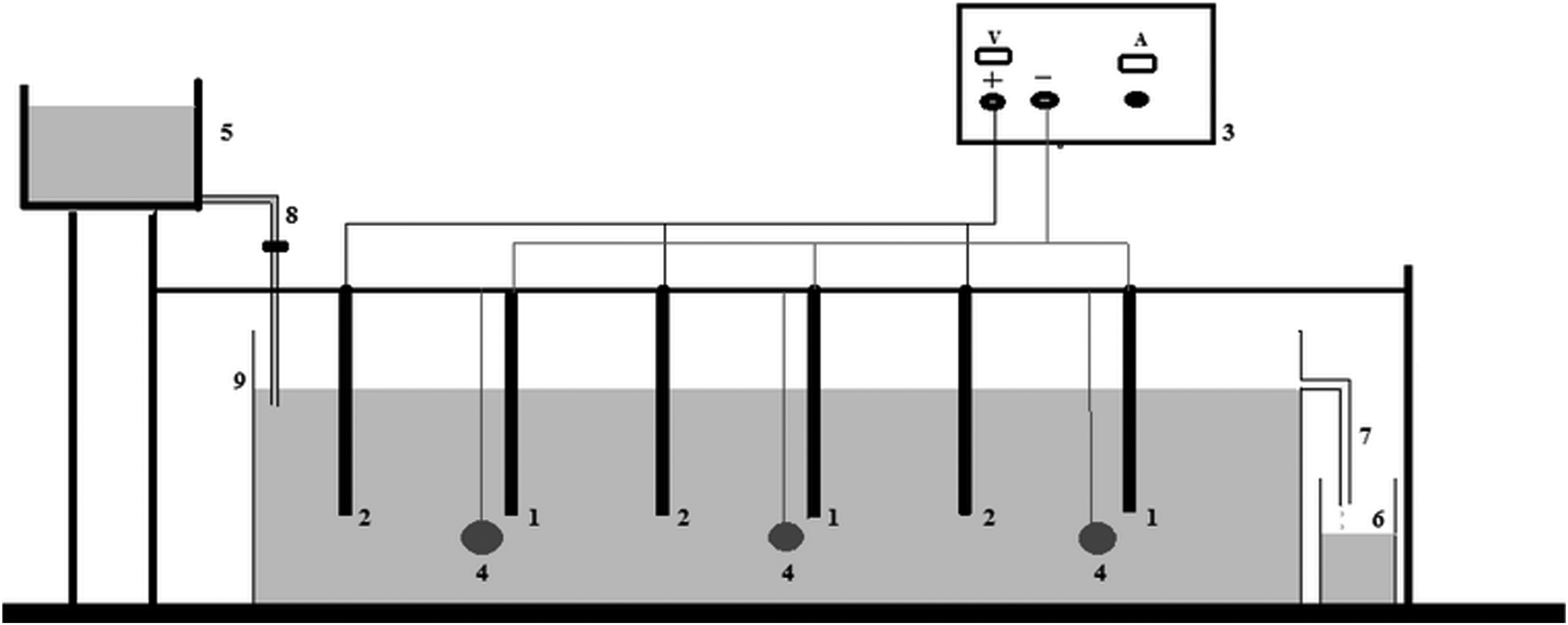
Experimental setup for continuous study. 1, cathode; 2, anode; 3, DC power supply; 4, aerator; 5, collection tank; 6, inlet tank; 7, outlet; 8, inlet; 9, electrotytic cell.
Results and Discussion
Effect of Fe2+ concentration
Fe2+ concentration is an important parameter that has great control over EF reactions (Ramirez et al., 2005). Since the generation of hydrogen peroxide depends on the applied voltage, cathode material, solution pH, etc., the efficiency of the EF process depends more on ferrous ion concentrations. Excess or shortage of any of these two reagents results in the occurrence of scavenging reactions [Eqs. (5) and (2)] (Tang and Huang, 1997; Lopez et al., 2004). Investigations have shown that best oxidation is attained [Eq. (12)] when neither H2O2 nor Fe2+ is overdosed to make maximum hydroxyl radicals available for the oxidation of organic compounds (Pignatello et al., 2006; Brillas et al., 2009). In the EF process, the electrolytic generation rate of H2O2 at constant current density, inner electrode spacing, solution pH, and electrode area is constant. Therefore, the generation of hydroxyl radical and thus the efficiency of the EF process depend more on ferrous ion concentrations.
To find the effect of FeSO4 catalyst concentrations on SA oxidation in a continuous stirred tank reactor (CSTR) rector, electrolysis was carried out for a period of 10 h by varying the Fe2+ concentration from 2.5 to 15 mg/L. A 100 mg/L SA solution with pH of 2.5, electrode distance of 3 cm, flow rate of 10 mL/min, and voltage of 2.5 V was used for all the experiments. The results are shown in Fig. 2: 41%, 57%, 43%, and 37% oxidation was obtained for 2.5, 5, 10, and 15 mg/L catalyst concentrations after 10 h of electrolysis, respectively. As can be seen from Fig. 2, up to 5 mg/L, the percentage of SA oxidation increased with an increase in catalyst concentrations. This is due to the increase in production of •OH at the surface of the cathode [Eq. (1)] with increase in ferrous ion concentrations leading to the enhancement in SA oxidation with time. Oturan et al. (2000) reported that 0.5 moles of oxygen is required for two moles of hydroxyl radical in the EF system. Since the production of hydroxyl radical depends on the concentration of hydrogen peroxide, very less concentration of oxygen molecules is required for the production of hydrogen peroxide. This is mainly due to the excess production of oxygen molecules at the anode by water oxidation (Oturan et al., 2000). Therefore, at lower concentration of ferrous ions, the excess of hydrogen peroxide in the system will cause hydroxyl radical scavenging reactions as in Equation (5) (Panda et al., 2011).
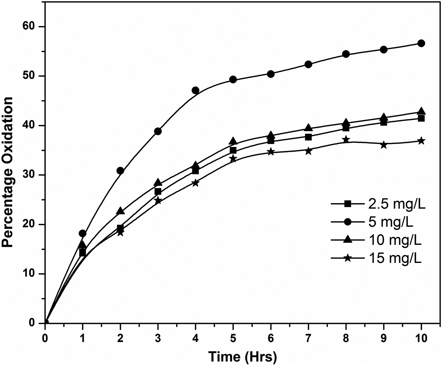
Effect of initial Fe2+ concentrations on SA oxidation. Solution pH: 2.5; inner electrode spacing: 3 cm; inlet flow rate: 10 mL/min; applied voltage: 2.5 V. SA, salicylic acid.
However, a further increase in catalyst concentrationss decreased the percent oxidation of the system. This is due to the fact that excess Fe2+ molecules compete with the SA molecules for the available •OH [Eq. (2)] (Benitez et al., 2001) and thus decreases the oxidation efficiency. Another cause for this is the deposition of Fe3+ ions on the surface of the cathode that will inhibit the electro generation of H2O2 (Wang et al., 2010). Thus, a suitable concentration of Fe2+ was an important parameter in the EF reaction. A concentration of 5 mg/L of Fe2+ was selected for further experiments.
Effect of pH
Efficiency of the EF process depends more on solution pH than other key operating parameters, because H2O2 production and relative concentration of ferrous ion in the Fenton electrolytic system depends more on solution pH. Equation (6) indicates that pH value of solution is one of the important factors affecting H2O2 generation because it converts the dissolved oxygen to hydrogen peroxide by consuming the protons in the electrolyte at acidic conditions (Mingyu et al., 2005).
The effect of pH was investigated by treating a 100 mg/L SA solution with 5 mg/L Fe2+ of catalyst concentration, 3 cm electrode distance, 10 mL/min flow rate, and 2.5 V voltage by varying the pH values from 2 to 3.5 in a CSTR reactor. The results are shown in Fig. 3. The percent oxidation that corresponds to pH values 2, 2.5, 3, and 3.5 was 59%, 70%, 57%, and 25%, respectively. When the pH decreased to 2.0 from 3, SA oxidation efficiency of the EF process was decreased. Two mechanisms might explain such a trend. First, the formation of oxonium ions [Eq. (13)] led to the deactivation of H2O2, which in turn reduced the production of hydroxyl radicals (Zhou et al., 2007). Second, increase in the scavenging effect of H+ ions and hydroxyl radicals led to the reduction of SA oxidation (Tang and Huang, 1997). It was observed that, the SA oxidation efficiency reduced when the pH of the solution was increased from 2.5. This is mainly due to the formation of excess ferric hydroxo complexes at higher pH values. This leads to decrease in ferrous ion concentrations in the solution and decrease in the Fenton reaction frequency.
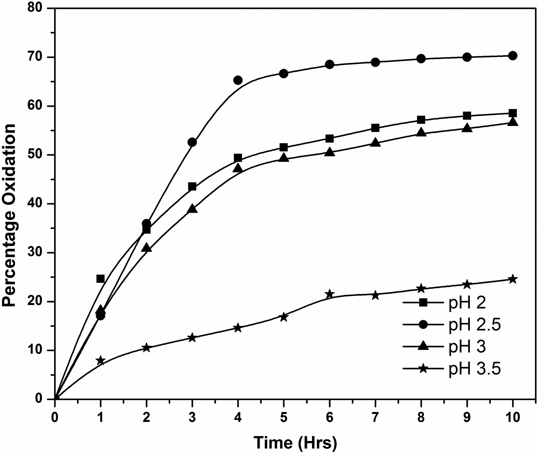
Effect of pH on SA oxidation. Inner electrode spacing: 3 cm; ferrous concentration: 5 mg/L; inlet flow rate: 10 mL/min; applied voltage: 2.5 V.
Most of the studies reported that the Fenton process has an optimal at pH of 3 (Nidheesh et al., 2013). For SA oxidation, a significant difference has been observed between pH 3 and 2.5. This may be due to the difference in speciation of ferrous ions at various pH values. Wells and Salam (1965, 1968) reported that the majority of ferrous ions will be in the form of Fe2+ at pH less than 3. This helps the rapid degradation of SA at pH 2.5, by the Fenton reaction. Complex formation of SA with ferric ion is a well-known phenomenon. This complex formation has an optimal pH around 2.6–2.8 (Mehlig, 1938). Therefore, at pH 3, the amount of complex formation with ferric ions (produced from Fenton reaction) and SA is higher compared with pH 2.5. This reduces the effective concentration of iron available for EF at pH 3 and results in less SA oxidation rate.
Effect of voltage
Voltage is another important parameter influencing the efficiency of EF reactions. It can influence the generation of H2O2 [Eq. (6)], which in turn enhances the production of hydroxyl radicals [Eq. (1)] (Panizzaa and Oturan, 2011). To study the effect of voltage on the oxidation of SA, experiments were conducted at different voltages varying from 1.5 to 3.5 V. A catalyst concentration of 5 mg/L, electrode spacing of 3 cm, flow rate of 10 mL/min, and a pH of 2.5 was maintained for all the experiments. The results are shown in Fig. 4. Oxidation efficiency increased from 28% to 70% with the increase in voltage from 1.5 to 2.5 V. This enhancement of oxidation is due to the production of greater amounts of •OH from Fenton reaction [Eq. (1)] by the faster production of H2O2 at the cathode [Eq. (6)] (Ruiz et al., 2011). The increase of the applied current enhances hydrolysis of Fe3+ ions and formation of Fe(OH)3(s), which consequently inhibits both the regeneration of Fe2+ ions and the production of OH• radicals (Qiang et al., 2003; Hsueh et al., 2005). The formation of ferric–hydroxyl complexes not only decreases iron catalyst activity and Fe2+ regeneration, but also retards dissolved oxygen mass transfer and H2O2 formation by its presence in the solution and formation of a coating on the electrode surface (Zhang et al., 2009). On the other hand, it was observed that the percent oxidation was dropped dramatically from 70% to 39% when the applied voltage increased from 2.5 to 3.5 V (Fan et al., 2010). The reduction in SA oxidation is mainly due to the increase in hydrogen gas evolution at cathode as in Equation (14), formation of water as in Equation (15), and hydrogen peroxide decomposition (Zhang et al., 2006; Özcan et al., 2008b). In addition, the temperature of the solution increases with an increase in applied voltage. This decreases the solubility of oxygen and enhances the H2O2 decomposition rate in the electrolytic system (Özcan et al., 2008a).
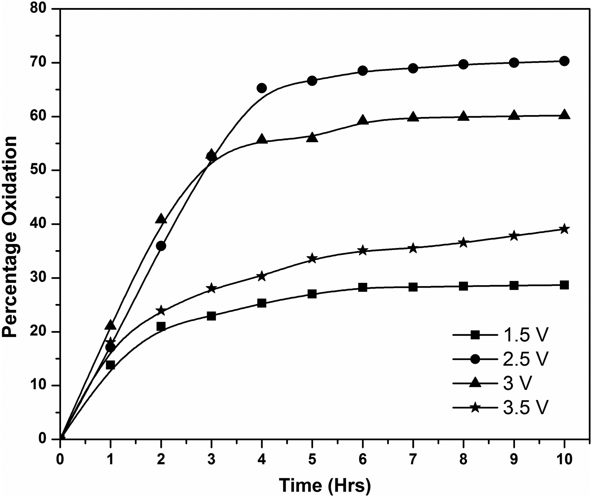
Effect of voltage on SA oxidation. Inner electrode spacing: 3 cm; ferrous concentration: 5 mg/L; inlet flow rate: 10 mL/min; solution pH: 2.5.
Effect of flow rate
The effect of flow rate on the oxidation of SA was examined by electrolyzing 100 mg/L of SA solution of pH 2.5 at 5, 10, and 15 mL/min. The corresponding SA oxidations are depicted in Fig. 5. As can be seen in Fig. 5, the oxidation corresponding to 5, 10, and 15 mL/min flow rates are 75.00%, 70.29%, and 56.65%, respectively. The experimental results show that the oxidation of SA from an aqueous solution increases with a decrease in the flow rate. Percent oxidation of SA was found to be high for very slow flow rates, since the residence time of the electrolyte solution inside the electrolytic cell was very high. Thus, for low residence time of the electrolyte solution inside the cell, the percentage oxidation of SA was found to be decreased with high flow rates (Prabhakaran et al., 2009). To balance the treatment capacity and oxidation, a 10 mL/min flow rate was selected for further experiments.
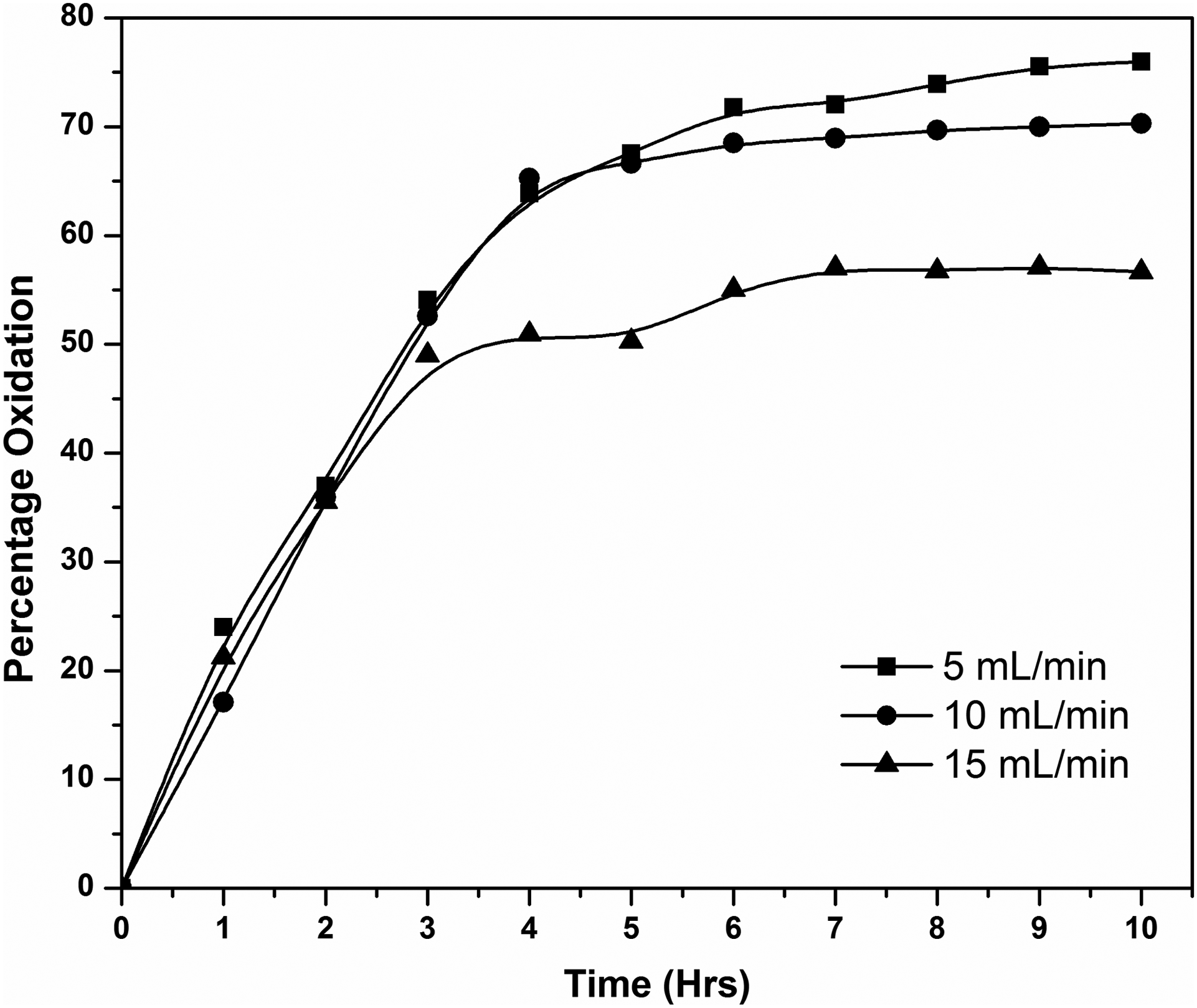
Effect of flow rate on SA oxidation. Solution pH: 2.5; inner electrode spacing: 3 cm; ferrous concentration: 5 mg/L; applied voltage: 2.5 V.
Effect of electrode spacing
To find the effect of electrode spacing on SA oxidation in a CSTR reactor, electrolysis was carried out for a period of 10 h by varying the electrode space from 2 to 5 cm. A catalyst concentration of 5 mg/L, voltage of 2.5 V, flow rate of 10 mL/min, and a pH of 2.5 were maintained for all the experiments. The results are shown in Fig. 6. It was found that the electrode spacing significantly affect the efficiency of this system. The oxidation of SA was 43%, 70%, 44%, and 40% when the electrode spacings were 2, 3, 4, and 5 cm, respectively. The oxidation of SA increased with in electrode spacing from 2 to 3 cm. Such promotion could be attributed to the enhancement of ion transfer at short electrode spacing, which resulted in the rapid regeneration of Fe2+ ions at the cathode surface. Further, it was observed that the percent oxidation was reduced from 70% to 40% when the electrode spacing increased from 3 to 5 cm. The negative effect of the higher electrode spacing on the SA oxidation can be explained by the decrease of the mass transfer of Fe3+ions between electrodes, which is necessary for the regeneration of Fe2+ ions [Eq. (7)] (Fockedey and Lierde, 2002). The rate of electro regeneration of Fe2+ decreases with the increase in inner electrode gap due to the reduction of the mass transfer of Fe3+ to the cathode surface (Zhang et al., 2006), leading to the reduction in the rate of generation of hydroxyl radical. Electro-regenerated Fe2+ will get oxidized to Fe3+ at a shorter electrode distance as in Equation (11) (Zhang et al., 2006). Fenton reactions get inhibited by this oxidation and result in a decrease in the SA oxidation rate. In addition, consumption of current was increased with a decrease in electrode spacing due to scavenging reactions as given in Equation (11), leading to the increase in cost of operation.

Effect of electrode spacing on SA oxidation. Applied voltage: 2.5 V; solution pH: 2.5; ferrous concentration: 5 mg/L; inlet flow rate: 10 mL/min.
Conclusions
The oxidation of SA in an aqueous medium by the EF process in a CSTR under various operating conditions was investigated. Continuous experiments in saturated air conditions determined that the optimal values for the oxidation of SA were 5 mg/L Fe2+, pH 2.5, voltage 2.5 V, and electrode spacing 3 cm. Under these optimal conditions, a maximum SA oxidation of 70% was obtained. It is obvious that the CSTR was able to operate without operational problems, and attaining good SA oxidation depended on the residence time without the addition of other oxidizing agents.
Footnotes
Author Disclosure Statement
No competing financial interests exist.