
Abstract
Abstract
Improving designs of facilities that employ floc blankets in a water treatment process train to ensure stable performance is desirable, as is an understanding of suitable operating conditions to maintain a functional floc blanket in the system. By considering sequential processes when choosing design parameters, the whole system can be optimized to produce high quality effluent at low cost. A lab scale water treatment system with flocculator, floc blanket, and lamellar sedimentation was used to evaluate the effect of energy dissipation rates (EDR) in the inlet jet to the floc blanket on performance of the system as a whole. Results show that presence of a floc blanket provided an additional factor of 8 decrease in settled water suspended solids concentration at an upflow velocity 1.2 mm/s. Inlet jet EDR did not impact system performance until ∼300 mW/kg after which settled water turbidity increased. At the lower end of inlet jet EDR tested, the jet was unable to resuspend settled flocs. Given that plant performance was acceptable at higher inlet jet EDR, smaller inlet jets with a higher velocity could be used to ensure resuspension of flocs for continuous hydraulic cleaning.
Introduction
N
Floc blankets are fluidized beds of flocculating particles (flocs) that are created under upflow (as opposed to horizontal flow) conditions in a sedimentation basin. Ideal sedimentation tanks should provide efficient particle removal to achieve long runtimes for downstream filters while minimizing downtime for cleaning of the sedimentation tank. Floc blankets can provide improved particle removal without increasing the size of a sedimentation tank. Floc blankets have the added benefits of:
• hydraulically eliminating sludge from the sedimentation tank without any moving parts • reducing biologically mediated gas production from settled solids • dissipating the momentum of the influent water and producing uniform vertical fluid velocities entering overlying plate settlers • enabling the construction of sedimentation basins that are less than 2 m deep.
Enhanced colloid capture in a floc blanket has been attributed to colloidal attachment to suspended flocs (Edzwald, 2011; Binnie and Kimber, 2013); however, the specific removal mechanisms have not been proven. Sustained operation of a flocculation/sedimentation treatment train with a floc blanket requires an understanding of conditions that may result in floc blanket failure and the ensuing high turbidity effluent. Failure to adequately operate a floc blanket is linked to pathogenic outbreaks (Logsdon, 2006). Therefore, improving the designs of water treatment facilities that employ floc blankets in the process train to ensure stable performance is desirable, as is an understanding of suitable operating conditions.
AguaClara is a program at Cornell University that researches, invents, and designs ultra low energy (15 J/L) municipal water treatment facilities that operate without the use of electricity. Sedimentation tanks designed by AguaClara (http://aguaclara.cornell.edu/implementation/design/) employ a sloped-bottom design that injects water into the bottom of the tank through a manifold that creates a line jet (Fig. 1). The sloped bottom allows settled flocs to form a floc density current and slide down to be resuspended by the incoming jet of flocculated water. If the momentum of the inlet jet is sufficient, the density current with a high concentration of flocs is returned to the floc blanket instead of accumulating as sludge in the bottom of the tank. This zero sludge design eliminates the need for mechanical sludge removal equipment. The AguaClara sedimentation tank can operate continuously by wasting excess floc blanket solids across a floc weir into a floc hopper. The floc hopper is drained periodically or continuously (while the sedimentation tank is still running) to remove consolidated solids.
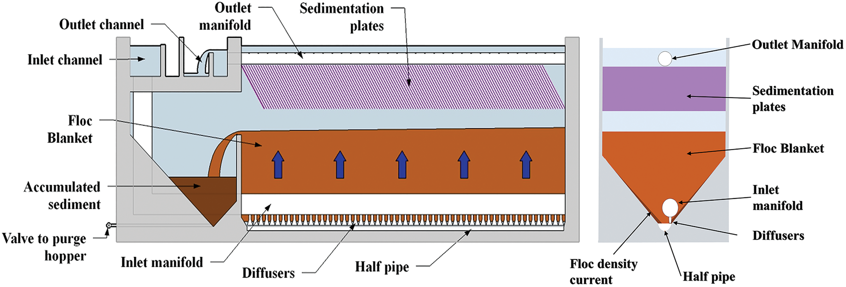
Schematic (front and side view) of the AguaClara Sedimentation Tank Design.
Residence time, velocity through conduits, upflow velocity (surface loading rate), and velocity gradient are key parameters used for water treatment facility design. For conditions of turbulent flow, the energy dissipation rate (EDR) is a parameter that controls the floc aggregation rate and the maximum floc size (Cleasby, 1984). Evidence from tests of coupled flocculation, sedimentation systems is often lacking to justify suggested design parameters. It is not clear how individual processes can be modified to optimize the whole treatment process sequence. The 10 State Standards suggest avoiding an increase in velocity and velocity gradient between flocculation and sedimentation basins (Recommended Standards for Water Works, 2012) presumably to avoid breakup of flocs. In some sedimentation tank designs the inlet consists of a manifold of relatively small diameter orifices. If velocity is held constant, the EDR increases as the relevant length scale of the flow decreases [see Eq. (1) adapted from Baldyga et al. (1995)] and maintaining the same EDR as was used in the flocculator would require lower velocities in the inlet jets than in the flocculator. The EDR of the jet is given:
where ɛJet is the EDR (mW/kg of fluid mass), Π Jet = experimental coefficient dependent on jet parameters (round, plane, bounded, etc.), VJet is the velocity of the jet (m/s), and DJet is the diameter of the jet. According to the results compiled by Baldyga et al. (1995), Π Jet for an axisymmetric jet has a value of ∼0.5.
Other design guidelines and research suggest that use of higher EDR (a parameter closely related to the velocity gradient that describes the intensity of mixing) to create small, dense flocs would enhance removal in systems with direct filtration (Bache and Gregory, 2010; Edzwald, 2011; Binnie and Kimber, 2013). Therefore, conduits between flocculator and sedimentation unit processes could be smaller with high EDR without negatively impacting performance. Some studies have considered the impact of fluid shear on flocs but this parameter does not provide conclusive expectations as to whether plant performance would change. For example, if lamellar plate settlers are used above a floc blanket, flocs broken by an increase in EDR may still be large enough to be captured. Conversely, an increase in floc size does not necessarily imply an improvement in plant performance. The goal of water treatment is to produce low turbidity water, not to produce large flocs.
Design of entry conditions for flocculated suspensions into sedimentation tanks is commonly constrained to minimize breakage of flocs and, in the case of horizontal sedimentation tanks, to not scour settled sludge (Edzwald, 2011). However, resuspending settled flocs is necessary to build a floc blanket and provides a method to eliminate sludge accumulation in the sedimentation tank. Therefore, application of entry conditions suitable for horizontal sedimentation tanks to AguaClara systems or other upflow systems with floc blankets is likely not appropriate.
Biodegradation of accumulated sludge in sedimentation tanks can cause performance to worsen by releasing gaseous products that carry particles to the surface and thus elimination of settled sludge can improve particle removal efficiency. The ability of an inlet jet to resuspend the floc density current of settled flocs in an upflow sedimentation reactor with a floc blanket is dependent on the velocity of the incoming water. If settled flocs are not resuspended, the inlet jet region will fill and create a nonuniform distribution of flow. Retaining the EDR used in the flocculator in the sedimentation tank inlet jets results in much lower velocities that may not be able to resuspend the floc density current. The only specific recommendations available for inlet velocities for the sedimentation tank are for horizontal flow, flat-bottomed tanks. Since sludge will be removed by mechanical cleaners at the bottom of a horizontal sedimentation tank, design recommendations suggest an inlet jet velocity of 10–25 mm/s in basins 2.1–4.3 m deep so that settled sludge is not scoured (AWWA/ASCE, 2012).
The goal of the sloped bottom in the AguaClara sedimentation tank design is to return settled flocs to the inlet jet where they may be resuspended to facilitate rapid floc blanket growth. When the floc blanket design incorporates a floc hopper that harvests flocs at the floc water interface, excess flocs can be wasted hydraulically from the floc hopper. With flat-bottomed designs, the sedimentation tank has to be cleaned by mechanical submerged moving parts that are prone to failure or manually cleaned resulting in downtime. Design recommendations and prior research (Head et al., 1997; Sung et al., 2004; Chen et al., 2006) for sedimentation tanks are confined to flat-bottomed tanks. The AguaClara design seeks to maintain a continuous operation by resuspending all settled flocs and wasting the floc blanket at the floc water interface over a floc weir into a floc hopper.
One of the key parameters in the design of the AguaClara sedimentation tank is the velocity of the inlet jet and the goal of this research was to determine how this parameter influences settled effluent turbidity of a sequential flocculation, floc blanket, and lamellar sedimentation process. A range of sedimentation tank inlet jet EDRs were tested to determine the limits of failure. The hypothesis was that an increase of inlet jet EDR at the entrance to the sedimentation tank would result in floc breakup that would cause an increase in settled water turbidity at higher EDR and that decreasing jet EDR would eventually result in a failure to resuspend flocs. Operational behavior of the floc blanket was also observed and is discussed.
Experimental Protocol
The lab scale experimental apparatus was the same as described by Hurst et al. (2014) with the exception that a floc weir was used to limit floc blanket height and almost all influent fluid was removed from the reactor by passage through tube settlers. A schematic of the apparatus is provided in Fig. 2. Aerated tap water (average pH 7.36, total alkalinity 131 mg/L as CaCO3, total hardness 150 mg/L as CaCO3, dissolved organic carbon 1.83 mg/L, City of Ithaca, 2014) was mixed with an 8 gram/L stock kaolinite clay suspension (R.T. Vanderbilt Co., Inc. Norwalk, CT) to form a 100 Nephelometric Turbidity Unit (NTU) synthetic raw feed water. To maintain a steady influent suspended solids concentration, an in-line turbidity meter monitored the turbidity and proportional integral derivative (PID) control was used to meter the clay stock. Polyaluminum chloride (PACl) (PCH-180 Holland Co., Adams, MA) was mixed to create stocks of 1.0 gm/L or 1.7 gm/L as Al and added to the influent stream using a peristaltic pump. The flow rate of the pump was adjusted to obtain a PACl dose of 2.8 mg/L as Al to the influent during experiments.

Design schematic of experimental apparatus. Influent to the sedimentation tank from the flocculator entered through inlet jet tubes of variable size. The downward direction of the influent flow is redirected upward by the semicircular jet reverser bottom geometry. A small percentage of the flow insufficient to supply an additional tube settler was sent to waste.
Flocculation was achieved by a 121 m coiled tube flocculator (tube inner diameter of 9.5 mm, coil diameter of 130 mm). The EDR in the flocculator was calculated based on the head loss of a helically coiled tube using the Dean number (Tse et al., 2011). Two upflow velocities in the floc blanket were used for experiments, 1.2 and 1.6 mm/s, and were achieved by increasing the experimental flow through the flocculator. Table 1 shows hydraulic and mixing parameters in the flocculator for each upflow condition.
Capture velocity (also referred to as the critical velocity) of the tube settlers was set at 0.1 mm/s for both upflow velocities; an additional tube settler was used to remove additional flow in the higher upflow velocity condition. The EDR in the inlet portion of the sedimentation tank was changed by altering the diameter of the tube delivering flocculated water to the bottom of the tank.
To calculate maximum EDR for the jet, Equation (1) is used and Π Jet approximated to 0.23 by computational fluid dynamic simulation of 2-D jets. This value falls within experimental results of 0.23 for a plane, bounded jet (Haarhoff and Van Der Walt, 2001) and 0.5 for a round, free jet (Baldyga et al., 1995).
After the fluid exits the inlet jet tube, it travels around the jet reverser and begins to expand in the bottom of the tank. When the jet exits the tube the cross section of flow is circular. As the fluid travels around the jet reverser, it expands to the width of the experimental tank and becomes rectangular (Fig. 3). When the jet exits the reverser, it is a plane jet. Flow rate and velocity are conserved, so the cross-sectional area of the flow remains the same such that Atube = APlaneJet. The smallest dimension of flow becomes the smallest dimension when the jet exits the reverser. The area of the plane jet is calculated:
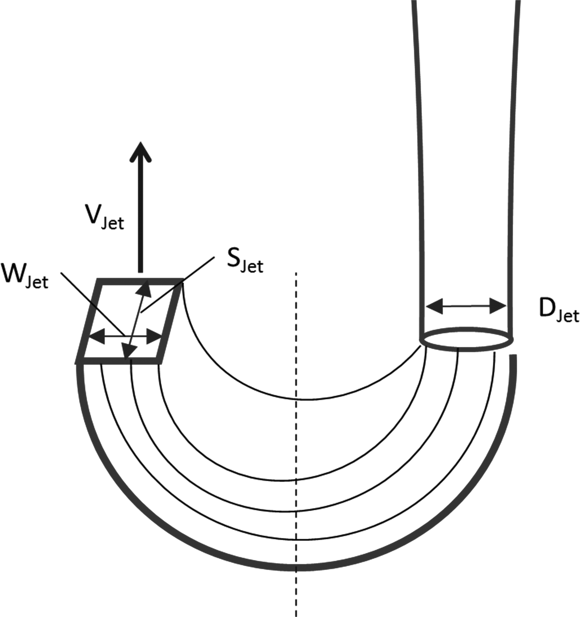
Diagram of changing relevant flow dimensions in the jet reverser.
where STank is the width of the tank (12.7 mm) and WJet is the width of the jet. DJet then becomes WJet in Equation (1) and is used in jet EDR calculations.
The range of tube diameters tested was 2.0–11.7 mm, which corresponded to maximum EDRs ranging from 0.25 to 337,000 mW/kg (Fig. 4), an exit velocity that varied from 0.06 to 1.9 m/s and a calculated inlet jet tube shear head loss of 1.6 × 10⁻³–8.4 m. The lowest velocity jet tested was more than double the maximum velocity recommended to prevent particle scour in horizontal sedimentation tanks (AWWA/ASCE, 2012).

Energy dissipation rates created by each jet diameter for upflow velocities of 1.2 and 1.6 mm/s.
Images of the floc blanket were collected every 60 s with a Basler (Basler, Ahrensburg, Germany) color SCA640-70FC IEEE-1394B (658 X490 pixels) using an 8 mm lens. Effluent turbidity readings were collected at 5 s intervals for the duration of each experiment using an inline turbidity meter (HF Scientific Microtol Inline Turbidity Meter).
Visual regions of interest used for image analysis of blanket and supernatant (i.e., fluid above the floc water interface) suspended solids concentrations are shown in Fig. 5 along with the region used to determine floc blanket height. Suspended solids concentrations were determined according to methods described by Hurst et al. (2014) based on absorbance of incident light.
Regions of interest selected for image analysis of floc blanket (solid line), supernatant (long dashed line), and floc blanket height (short dashed line).
Failure of the floc blanket tube settler system was defined as observation of an effluent turbidity in excess of 3 NTU (deemed to be an upper limit for water to be treated by filtration) or when the influent jet was unable to resuspend the floc density current coming from the sloped bottom into the jet reverser region. These failures cover conditions at the highest and lowest jet EDRs that would prevent the floc blanket sedimentation system from producing an acceptable quality of water.
System performance before a floc blanket was determined by extracting effluent turbidity data at one residence time of the entire system (referred to here as the experimental conditioning phase). The first full residence time (44 and 37 min for 1.2 and 1.6 mm/s upflow velocity, respectively) was required for the initial particle-free water in the experimental apparatus to exit the system. This time was sufficient for the first fluid packet of flocculated water to pass through the system and reach the effluent turbidity meter. Effluent turbidity detected at this point in time was not influenced by the presence of a floc blanket.
Results
A floc blanket formed for all experimental conditions tested. The total time required to form a blanket ranged from 3 h at the 1.6 mm/s upflow velocity to 5 h at the upflow velocity of 1.2 mm/s.
There were two potential failure modes of the system when changing the inlet jet EDR: (1) the effluent turbidity was greater than 3 NTU and (2) the jet was unable to resuspend the density current of settled flocs, allowing settled solids to fill in the inlet jet reverser. In the first failure mode, it is assumed that flocs were broken by the increased EDR to a size and quantity that could not be captured by the tube settlers or reformed in the floc blanket. The latter failure mode (accumulation of solids in the jet reverser region) would result in one or more of the following: uneven flow distribution in the tank because the inlet was occluded resulting in preferential flow through consolidating sludge in the jet region, and the inability for complete resuspension of settled solids needed to support continuous operation.
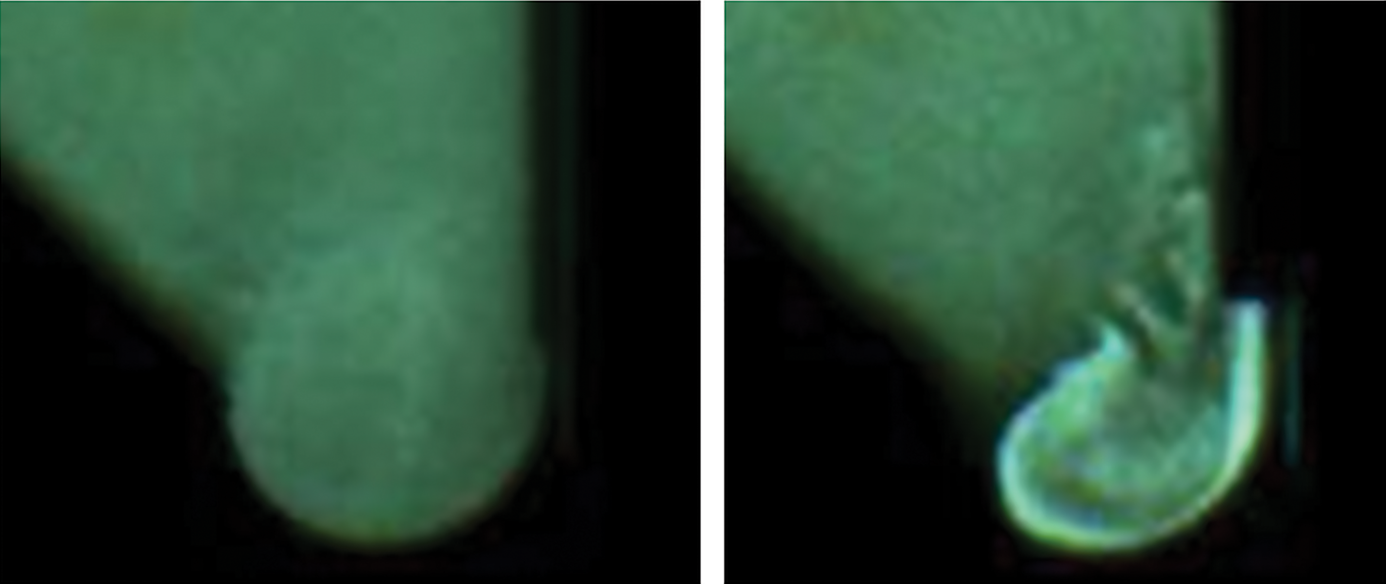
During experimentation, the fluid exiting the inlet jet tube traveled in a semi-circular flow through the bottom geometry (referred to here as the jet reverser) and mixed with the incoming floc density current. The upward vertical momentum of the jet exiting the reverser region must be higher than the downward momentum of the incoming floc density current to prevent accumulation of flocs. The balance between the momentum of the jet and floc density current was reflected in the angle between the floc density current and the upward jet (Fig. 6). As the inlet jet diameter increased (EDR decreased) and mass flow rate remained constant, jet velocity decreased causing the momentum of the incoming flow to decrease. Since momentum of the jet decreased as jet diameter increased and the floc density current did not change considerably, the downward momentum of the floc density current eventually exceeded the upward momentum of the inlet jet leading to failure. Thus, at failure there was insufficient vertical momentum to carry the settled flocs back up into the floc blanket (Fig. 6).

Close-up of the confluence of the floc density current and the upward jet at steady state for 7.05 mm (left) and 8.9 mm (right) jet diameters. The angle of jet interaction with the density current (indicated with a superimposed line) increased as the jet velocity decreased leading to failure for low momentum jets.
Blanket, supernatant, and effluent concentrations for floc blankets at steady state
Floc blanket concentration in the sedimentation tank reached a steady value before the floc blanket reached the floc weir. Once the floc blanket developed a clear floc water interface and started growing in height, the floc blanket stayed at approximately the same suspended solids concentration for the rest of the experiment. The floc blanket grew to the height of the floc weir and then maintained a constant height by wasting over the floc weir.
Figure 7 provides an example run with images at times when the system is changing or at steady state. Once the system completed the conditioning phase (i.e., after one fluid residence time), the supernatant suspended solids concentration and effluent turbidity increased dramatically and then decreased as the floc water interface became apparent and the height of the floc blanket started increasing. The supernatant concentration steadily rose after the floc blanket developed and grew in height while the effluent turbidity steadily decreased. Once the floc blanket reached the floc weir and started wasting to the floc hopper, it was considered to be at steady state as the height was fixed and the floc blanket concentration remained the same.

Example experimental run with images at notable times.
For the range of EDR tested (excluding failures at the highest and lowest EDR), the average floc blanket concentration was 1,608 mg/L (σ = 294 mg/L) at the 1.2 mm/s upflow velocity and 1,145 mg/L (σ = 218 mg/L) at the 1.6 mm/s upflow velocity. Average supernatant concentrations were 193 mg/L (σ = 59 mg/L) and 159 mg/L (σ = 82 mg/L) for 1.2 and 1.6 mm/s, respectively. Average effluent turbidities were 0.74 NTU (σ = 0.67 NTU) and 0.72 NTU (σ = 0.92 NTU). Coefficient of variation for steady state floc blanket concentrations was 0.18 and 0.19 for 1.2 and 1.6 mm/s, respectively. Steady state concentrations for all locations monitored are presented in Fig. 8. At the largest jet EDR tested (337,000 mW/kg and 27,300 for 1.6 mm/s), the effluent turbidity was above 3 NTU resulting in system failure. The results reveal a steady increase in effluent turbidity beginning at ∼300 mW/kg before the system reached failure. In this region after the effluent turbidity begins to increase and before failure, it is expected that some flocs were broken and system performance was adversely affected by the high EDR in the influent jet.

System suspended solids concentrations during steady state as a function of jet energy dissipation rate for 1.2 mm/s (top) and 1.6 mm/s (bottom). Results shown are averaged over two residence times (1,200 s) of the sedimentation tank. Concentration of the floc blanket and supernatant corresponds with the first x-axis and effluent turbidity with the secondary y-axis.
System failure occurred at the lowest EDR tested at 1.2 mm/s (0.25 mW/kg) as the jet reverser began to fill in with the floc density current. Failure to resuspend settled flocs did not occur for any EDR tested at the 1.6 mm/s upflow velocity. Figure 9 shows an example of the system when the jet reverser is adequately cleared (left photo) and when it is being filled in (right photo).
Close-up images of the system not in failure at 2,500 mW/kg (left) and in failure as the jet reverser fills in at 0.25 mW/kg (right).
Performance with and without floc blanket
Overall floc blanket performance was defined in terms of the negative logarithm of the ratio of solids concentration in the effluent and influent (pC*) [Eq. (3)]. High values of pC* correspond to improved performance.
In all experiments, system performance increased in the presence of a floc blanket (Figs. 10 and 11), however, a smaller change in performance is noted at the extremes of inlet jet EDR for 1.2 mm/s. Performance with a floc blanket improved by an average of 0.9 pC* (i.e., an eight-fold decrease in effluent turbidity) across all EDRs not in failure at an upflow velocity of 1.2 mm/s and 0.4 pC* (2.5-fold decrease in effluent turbidity) for 1.6 mm/s upflow velocity.
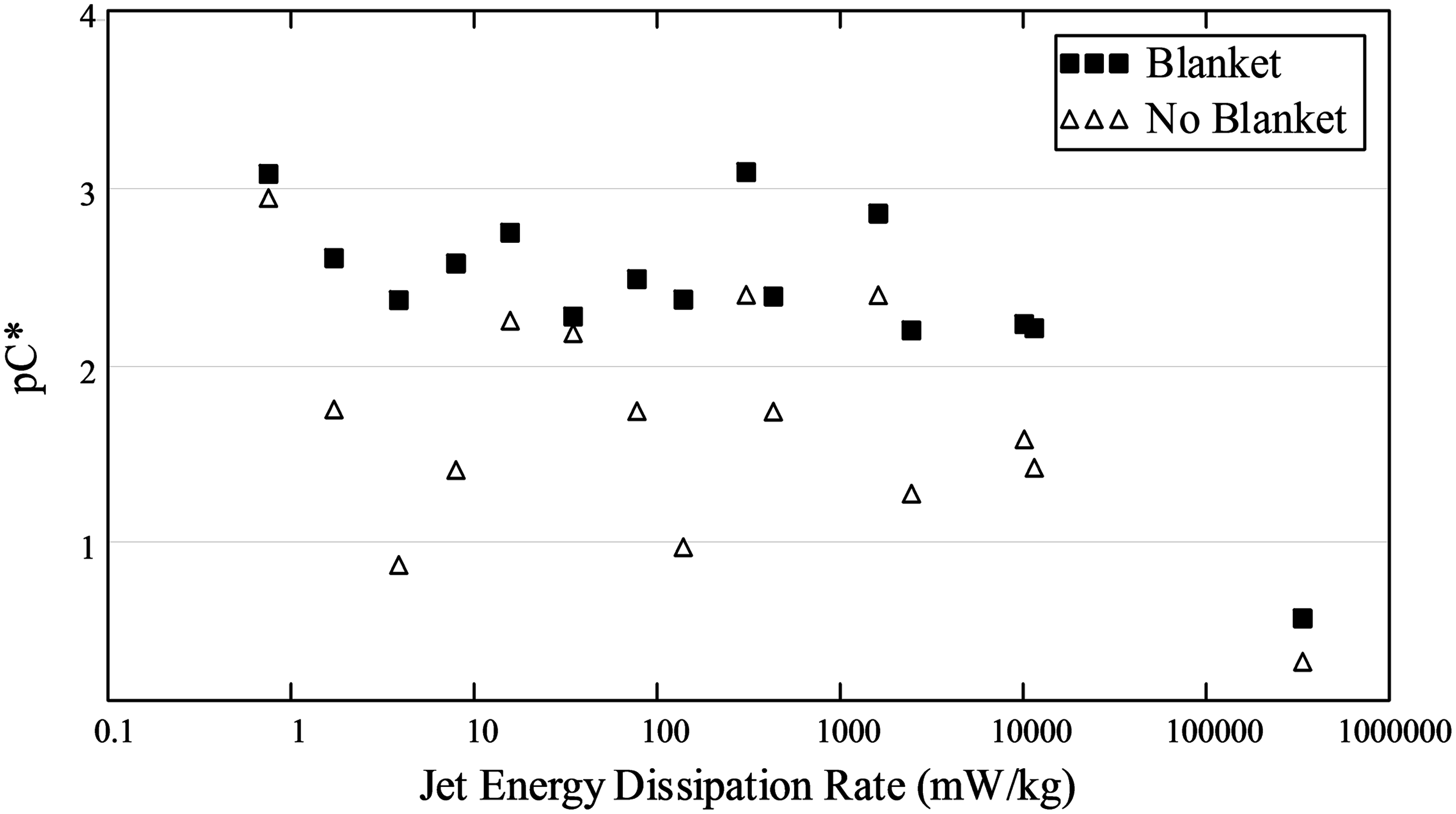
System performance with and without floc blanket at upflow velocity of 1.2 mm/s
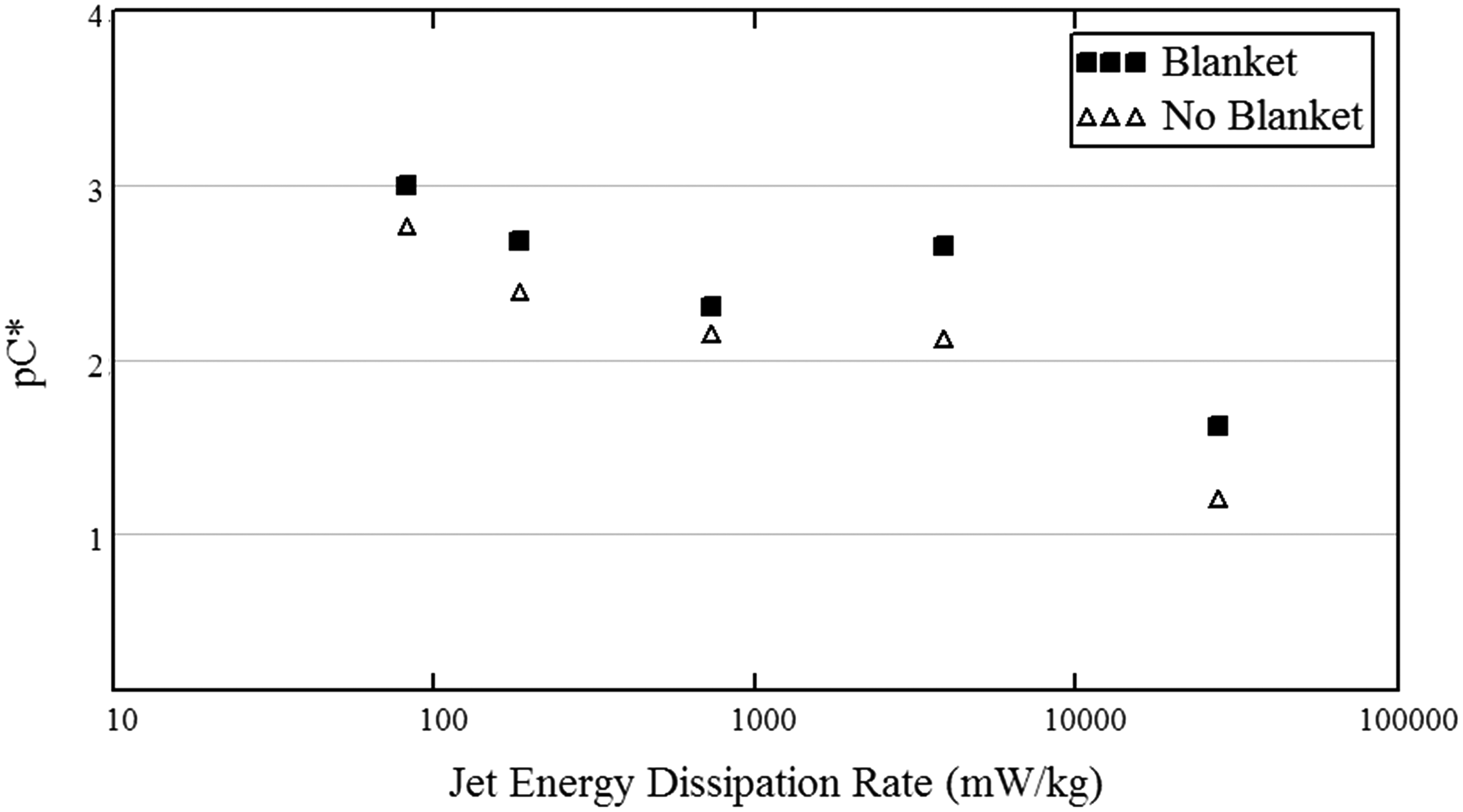
System performance with and without floc blanket at upflow velocity of 1.6 mm/s
Discussion
The effluent suspended solids concentration remained unaffected by inlet jet EDR until about 300 mW/kg and decreased below acceptable performance at 6,000 mW/kg as interpolated from Fig. 9. Based on this information, inlet jet EDR could be increased above that in current design guidelines without decreasing plant performance. Previous guidelines limit inlet velocity gradient (more correctly the EDR) to less than or equal to equivalent flocculator velocity gradient (Hudson 1981). This research has shown that when a floc blanket and lamellar settlers follow the flocculator, overall performance begins to decrease when the sedimentation tank inlet has an EDR that is greater than 60 times the EDR of the flocculator in the 1.2 mm/s case and 63 times greater in the 1.6 mm/s case (Fig. 8). Given that performance is still acceptable at higher jet EDR, smaller inlet jets with a higher velocity can be used to ensure the inlet jet is able to resuspend the floc density current and to decrease the required size of inlet manifolds.
Design guidelines suggest that flocs would have been broken to some degree in any EDR that exceeded the flocculator EDR. Given that deterioration in system performance was not observed until the inlet jet EDR was much higher than the flocculator (∼60 times higher for 1.2 mm/s and ∼63 times higher for 1.6 mm/s), the system can perform well with a higher inlet jet EDR. If flocs are indeed broken at an EDR that exceeds the flocculator EDR, then (1) the tube settler capture velocity was sufficient to capture the smaller flocs or (2) the floc fragments were captured in the floc blanket. Only at an EDR >300 mW/kg did the effluent turbidity begin to increase. A closer analysis of EDR gradient in the sedimentation tank influent jet would be needed to determine the actual size of the region where the maximum EDR is obtained.
Summaries
Based on the experimental results, inlet jets for floc blanket sedimentation systems could be designed at higher EDR and thus higher velocities to ensure floc density current resuspension without negatively impacting the effluent water quality. For the AguaClara design, a suggested EDR upper limit for the inlet jet is 300 mW/kg. For a 1 m wide sedimentation tank and an upflow velocity of 1 mm/s this corresponds to a velocity of 340 mm/s. At this velocity the minor head loss at the exit of the plane jet is 6 mm and that should be taken into account in the hydraulic design. It is important to note that average velocity gradient is not an appropriate design parameter for the flow passages between the flocculator and sedimentation tank if the goal is to prevent excessive breakup of flocs because flocs are broken by the maximum EDR they experience and the EDR is a function of the flow geometry and the velocity. In comparison to recommended values for inlet velocities of 10–25 mm/s (AWWA/ASCE, 2012), the results of this research suggest up to 340 mm/s is permissible for a 1.5 mm thick plane jet before a change in performance is apparent in the system. It is apparent that general water treatment plant design guidelines do not apply to the AguaClara system or by inference to other upflow sedimentation reactors with floc blankets, and suggest that design parameters could be reevaluated to optimize performance.
Only at extremely high inlet jet EDR did the experimental system produce an unacceptable water quality. At the lower end of EDR range tested, the jet was unable to resuspend the returning floc density current and led to sludge accumulation. In a full scale system, biodegradation of accumulated sludge could result in gas production; and dissolved gas flotation of flocs to the top of the sedimentation tank. To resuspend the floc density current, a minimum jet velocity of 75 mm/s is suggested for the given system and lab conditions. The inability of a jet to resuspend the floc density current could be better characterized by determining the momentum of the two flows (floc density current and inlet jet). Further research to determine the minimum inlet jet requirements to suspend the floc density current should be based on momentum to accommodate the changing flocculated water momentum and floc density current concentrations. The results of this research indicate that AWWA and 10 State Standard design guidelines for upflow sedimentation tank inlets such as the AguaClara design is not useful.
Increasing inlet jet EDR reduces conduit size without significantly changing particle removal efficiency. Since smaller conduits are less expensive, plant construction costs are less. There is ultimately a limit to the EDR that can be applied to a flocculated suspension before performance decreases in the system. However, there is a region before this limit where flocs appear to be broken into smaller aggregates that can still be captured by lamellar sedimentation where there is no decrease in performance. It is uncertain which mechanism (particle capture by the floc blanket or tube settlers) achieves the removal of broken flocs and further investigation into the removal of flocs and colloidal particles in a floc blanket system is needed. This information with additional research into the mechanistic interaction of the inlet jet flow with the floc density current could provide more definitive design guidelines based on a physical understanding of floc-shear interactions (rather than empirical) for both AguaClara and other sedimentation tanks.
Footnotes
Acknowledgment
This research was supported, in part, by National Science Foundation award ID 1437961.
Author Disclosure Statement
No competing financial interests exist