
Abstract
Abstract
Module configurations of membrane process substantially affect the biogas separation performances. In this article, the characteristics according to module configurations were investigated in terms of purity and recovery efficiency to improve the biogas availability through simultaneous utilization of carbon dioxide and methane. First, a single-stage permeation was tested, and methane having >97% purity was recovered, but the recovery efficiency dropped to below 40%; the simultaneous recovery of methane and carbon dioxide was impossible due to a trade-off. In carbon dioxide recovery experiment, high-purity carbon dioxide was recovered as well as almost all the methane in the biogas at >99% efficiency. In methane recovery experiment, high-purity methane (>97%) was produced, but recovery efficiency decreased to <71%. To improve methane recovery efficiency, low-quality gases (permeate gas of the second module, and retentate gas of the third module) were recycled to the feed; methane recovery efficiency subsequently improved, and high-purity carbon dioxide could be recovered at a high recovery efficiency. Finally, we discussed methods for effective biogas utilization according to module configurations.
Introduction
B
Biogas is usually utilized as a substitute for natural gas or as fuel for combined heat and power (CHP) and vehicles (Petersson and Wellinger, 2009; Thrän et al., 2014). For the efficient utilization of biogas, there remains a need to upgrade biogas by removing CO2. Current technologies for eliminating CO2 from biogas include the following: absorption by chemical solvents, physical absorption, pressure swing adsorption, cryogenic separation, membrane separation, and CO2 fixation by biological methods (Abatzoglou and Boivin, 2009; Ryckebosch et al., 2011). However, conventional technologies for CO2/CH4 separation such as amine scrubbing, water scrubbing, pressure swing adsorption, and cryogenic separation have drawbacks, based on the large size of the equipment required and their high-energy demand (Scholz et al., 2013).
Membrane separation technology has been introduced as a promising technology for overcoming the disadvantages of conventional gas separation processes. Membrane gas separation has a relatively high-energy efficiency, low capital cost, and low maintenance operation, in addition to a small footprint (Figueroa et al., 2008; Scholz et al., 2013). Also, the CO2 removed from biogas could be recovered as resource because there is no phase transformation. CO2 is the most well-known contributor to the greenhouse effect, although it can be used as a valuable energy source as a refrigerant for food preservation, as a beverage carbonation agent, and used in medical applications, supercritical solvents, chemicals for pH control in industrial processing, and as a neutralizing agent (Song, 2006; Luis et al., 2012; Zhang et al., 2013b). Despite this advantage, there is no study on CO2 upgrading and utilization in biogas.
Membrane processes have numerous advantages for gas separation, but single-stage permeation is insufficient to attain a high recovery efficiency with highly concentrated gases. There is a trade-off between the purity and recovery efficiency when separating gases through a membrane, since the gas separation performance depends on selectivity estimating the difference in the permeation rates of gas components (Robeson, 1991, 2008; Freeman, 1999). So, multistage permeation and recycling steps have been studied by a lot of researchers in attempts to overcome the drawbacks of single-stage permeation. Agrawal and Xu (1996) and Xu and Agrawal (1996) developed cascaded module configurations according to a number of compressors. Song et al. (2008) investigated multiple stages for CO2/N2 separation and that only permeate gas was used as feed gas of next stage. Multistage separation for CO2 capture from flue gas was simulated by Zhao et al. (2010). Optimum module configurations, including recycling step, were designed in terms of capital and operating cost for CO2 separation in natural gas (Datta and Sen, 2006; Hao et al., 2008; Ahmad et al., 2012). Module configurations about biogas separation were studied (Deng and Hägg, 2010; Makaruk et al., 2010; Koh et al., 2011). Studies on biomethane purification for the grid injection were also performed (Molino et al., 2013a, 2013b, 2015; Molino et al., 2013c; Iovane et al., 2014). However, most articles were only performed by simulation study with just a few module configuration concepts. Therefore, the experimental study on multistage biogas separation is required to demonstrate the separation performances according to module configurations based on experimental results.
Hence, this study was performed at experimental base and the purpose was to verify the simultaneous upgrading of CO2 and CH4 from biogas for effective utilization in the field. This study focused on finding novel operation methods regarding biogas upgrading and simultaneous recovery of CO2 and CH4. Eight multistage configurations for biogas separation were evaluated in terms of purity and recovery efficiency. The module arrangements were focused on their ability to attain >95% CO2 purity and >97% CH4 purity from biogas. Finally, methods for effectively utilizing this biogas were discussed.
Materials and Methods
Hollow fiber membrane module and synthetic biogas
Commercial hollow fiber membrane modules purchased from Airrane were selected for the biogas separation tests. The membranes in each module were fabricated from polysulfone (PSf) coated with polydimethylsiloxane (PDMS). Membranes based on a glassy polymer such as PSf membrane are known to have high selectivity but low permeance, whereas rubber-based membranes such as PDMS membrane have a high permeance but low selectivity (Yadvika et al., 2004). The single gas permeation of CH4 and CO2 was identified as 5.96 and 158 GPU, respectively, and the CO2/CH4 selectivity was estimated to be 26.5. Other information provided from the manufacturer is presented in Table 1. The SEM images of the hollow fibers showed an external diameter of 404 μm and an internal diameter of 245 μm (Fig. 1). The presence of macrovoids was confirmed by observing the cross-sectional view of the membrane; no cracks or defects were observed on the outer surface of the membrane.

SEM images of hollow fiber membrane:
The synthetic biogas used in this study was composed of 40% mole fractions of CO2 and CH4 as a balance. Although raw biogas included trace materials such as sulfur and moisture, the trace materials were removed through pretreatment in front of a membrane separation process (Petersson and Wellinger, 2009; Thrän et al., 2014). In addition, the H2S presence in the biogas did not represent a problem in terms of separated stage using polymeric membrane (Molino et al., 2013c). So, the mole fraction of the trace materials was not considered in separation test. The mole fraction of CO2/CH4, 60%/40%, was selected in consideration of the composition of raw biogas (Petersson and Wellinger, 2009; Thrän et al., 2014).
Biogas separation experiments
Biogas separation experiments for each module configuration were performed using a laboratory-scale membrane biogas separation system. The system, presented in Fig. 2, consisted of a gas cylinder and regulator, a gas thermostat, gauges for measuring the pressure and flow, membrane modules, and a control valve for regulating the retentate gas flow. The synthetic biogas in the cylinder was transported to the membrane module through the gas regulator and the thermostat. For the multistage experiment, the vacuum pump, which is more energy efficient than a compressor, was applied to transport permeates to the second or third stages (Brunetti et al., 2010). In this study, the temperature and pressure of feed gas in the first stage were fixed at 40°C and 0.7 MPa, respectively.
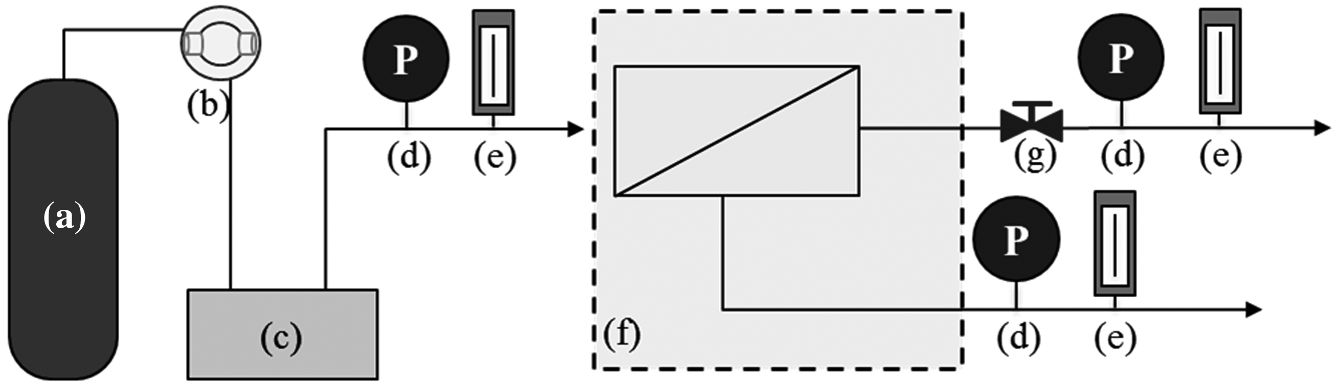
Schematic diagram of membrane gas separation system available for modification of module configurations:
The membrane separation section, shown in Fig. 2f, was changed according to the module configuration. Nine module configurations were considered, from single stage to triple stage (Fig. 3); letters P and R denote the permeate and retentate gases, respectively, and the following number indicates the stage of each module. For instance, P2 denotes the permeate gas from the second module. The flow and purities of CH4 and CO2 were measured at each module, respectively, with the purity values for the total permeate gas (TP) and total retentate gas (TR) being calculated based on the cumulative purities of the permeate and retentate gases.

Schematic diagrams of module configurations for biogas separation:
Module configurations, except Fig. 3a, were divided into two groups: CO2 recovery and CH4 recovery. First, to improve CO2 purity, module configurations were constructed with double and triple stages such that the permeate gas was transported to the feed gas of the next stage (Fig. 3b, c). The other configurations were selected in attempts to improve the purity and recovery efficiency of CH4. Serial configurations using retentate gas as the feed of the next stage were selected to produce high-purity CH4 (Fig. 3d, e). The configurations having a mixed triple stage were applied to improve the CH4 recovery efficiency while maintaining a high CH4 purity (Fig. 3f, g). Figure 3h and i, which includes a recycling process, was modified from Fig. 3d and f to further enhance the CH4 recovery efficiency. The raw data were arranged in Appendix Table A.
Analysis
The retentate and permeate gases separated from each membrane module were measured using a bubble flow meter (Gilibrator 2; Gilian) to confirm the flow, and a gas chromatography equipped with a thermal conductivity detector (Agilent 490; Agilent Technologies) to analyze the gas purity. All experiments were performed at various stage-cuts (θ), since stage-cuts affected the separation performance, including the purity and recovery efficiencies. Stage-cuts were estimated using the following equation (Chenar et al., 2006):
where θ is the stage-cut, which is expressed as the permeate gas over the feed gas. QFeed is the sum of QPermeate and QRetentate, and QPermeate and QRetentate are the total flows of permeate and retentate gases, respectively.
The recovery efficiencies estimated based on the total retentate or permeate gases were calculated as follows (Wang et al., 2014):
where
where
Results and Discussion
Selection of operating conditions
The effect of operating conditions such as pressure and temperature on separation performances in the membrane biogas separation process has been studied through preliminary tests. To identify the effect of temperature, tests were performed at low (10°C) and high (40°C) temperatures. Usually, permeance improved with increasing temperature, while purity deteriorated because of decreased selectivity (Ostwal et al., 2009). In our process, permeance was also increased at high temperature but the effect of temperature on purity deterioration was negligible. High temperature was selected considering real biogas temperature that biogas plants operated at mesophilic or thermophilic condition between 30°C and 60°C (Yadvika et al., 2004; Ward et al., 2008). To optimize operational pressure, tests were performed at 1, 3, 5, 7, and 9 bar. The CO2 recovery efficiency was increased until 7 bar, but reduced slightly at 9 bar. The reason about slight reduction was assumed to be the CO2 plasticization. Scholes et al. (2010) studied about CO2 plasticization of the PSf membrane, which was the same type of membrane we used. This article showed that permeability was increased at 10 bar, but purity was decreased due to selectivity decline by plasticization. A pressure of 7 bar was selected as optimum to avoid the risk on performance deterioration by plasticization.
Separation performances on single-stage permeation
Results of the single-stage separation (Fig. 3a) pertaining to the purity and recovery efficiency of CH4 in the retentate gas and CO2 in the permeate gas, respectively, are presented in Fig. 4. Improving CO2 purity to >95% was too challenging for these test conditions due to the low CO2 mole fraction in the feed gas, while CH4 purity was measured to be >97.57%.

Separation performances of single-stage permeation in terms of purities and recovery efficiencies.
The CH4 purity in the retentate gas was >97%, whereas the recovery efficiency of CH4 was <60%; the recovery efficiency of CH4 deteriorated with the increase in CH4 purity, thus indicating that the increase in CH4 purity led to an increase in CH4 losses. An opposite trend was observed in terms of CO2 purity and recovery efficiency in the permeate gas compared with the CH4 purity and recovery efficiency in the retentate gas. The CO2 purity increased at the low stage-cut, whereas the CH4 purity decreased; in contrast, the CO2 purity decreased at a high stage-cut, whereas the CH4 purity increased. There is a clear trade-off between the purities of CH4 and CO2, as well as between the purity and recovery efficiencies. Therefore, in a single-stage module configuration, it was not possible for high-purity CH4 to be produced at a high recovery efficiency nor could high-purity CH4 be recovered during the recovery of high-purity CO2. The limitation of separation performance on single-stage permeation was observed in other studies (Zhao et al., 2010, 2012). The studies to overcome the single-stage limitation were performed in addition to a single stage with permeate recycle (Kazama and Haraya, 2013; Zhang et al., 2013a). However, it has the disadvantage that energy consumption was dramatically increased.
Separation performances of multistage configurations for CO2 recovery
Double-stage permeation tests using the permeate gas as the feed (Fig. 3b) were performed to recover high-purity CO2. The CO2 purities measured in TP and CH4 purities measured in R1 and R2 are represented in Fig. 5. At stage-cut 0.21, the CO2 purity and recovery efficiency were 95.1% and 49.8%, respectively. The maximum CO2 purity recovered in this condition was 97.5%, whereas the recovery efficiency dramatically decreased to 17.8%. There is a trade-off between the purity and recovery efficiency (Robeson, 1991, 2008; Freeman, 1999).
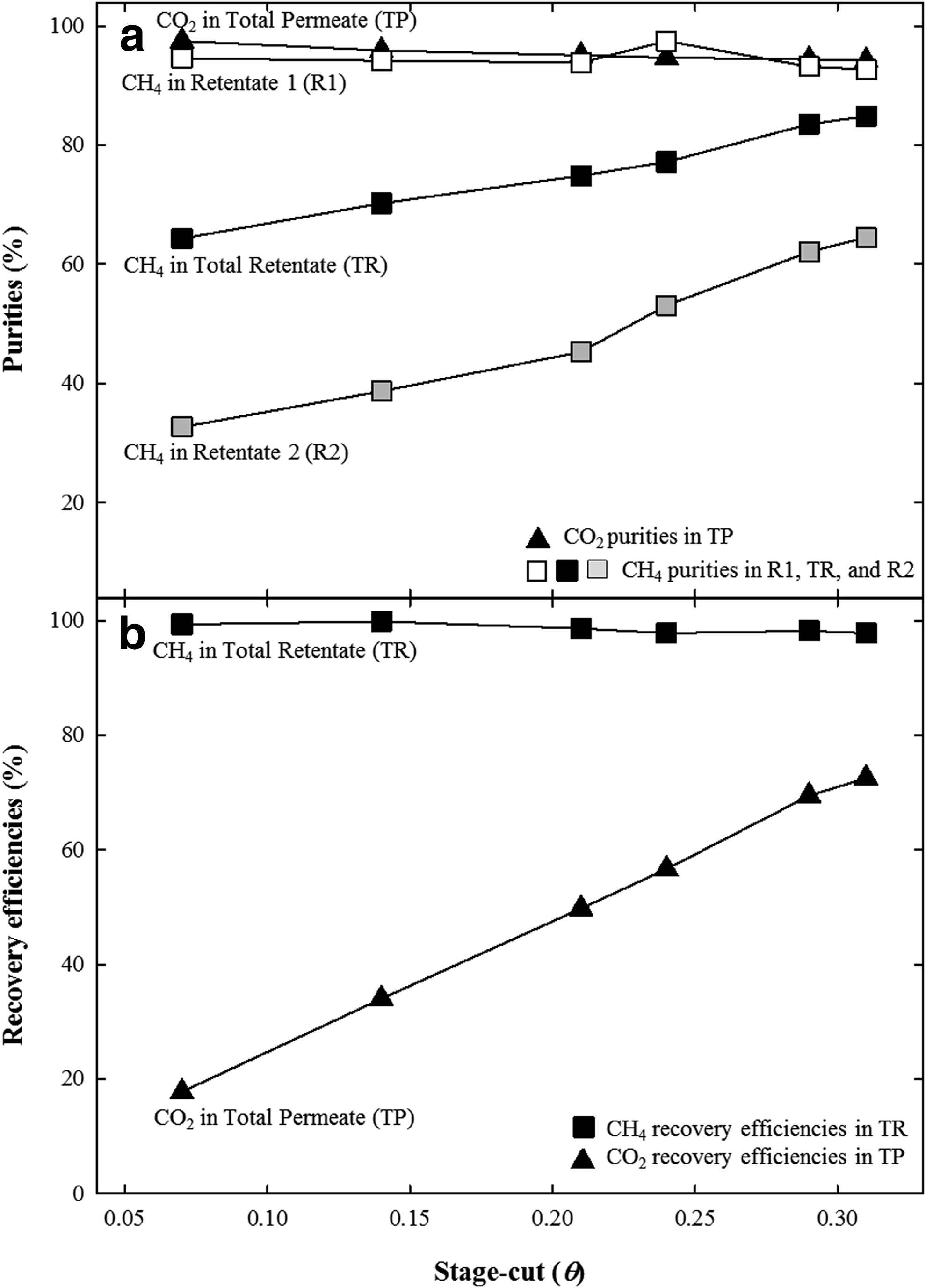
Separation performances of double-stage permeation for CO2 recovery (Fig. 3b):
CH4 purities in R1 were as high as 92.7–97.5% and those in R2 were as low as <64.5%. The reason for these results was that the CH4 content in the feed of the second stage (P1) was reduced through the first module. Total CH4 purities were measured as being between 64.3% and 84.8%, and the CH4 recovery efficiencies in the total retentate gases reached >97.9%. This value regarding CH4 recovery efficiency was quite an advanced value in comparison with other conventional processes such as absorption with water or polyethylene glycol (>97% efficiency) and pressure swing adsorption (95–98% efficiency) (Molino et al., 2015), even though the recovery efficiency of membrane process (>96% efficiency) was usually lower than other upgrading processes. Therefore, using the double-stage configuration for CO2 recovery, high-purity CO2 was recovered and retentate gases were recovered with minimal CH4 losses. In other CO2/CH4 separation experiments using different membranes such as polyimide and polyphenylene oxide membrane, the increase of CO2 purity and methane loss also occurred with increasing stage-cut (Pourafshari Chenar et al., 2008).
Triple-stage permeations in which the permeate gases transported to the feed gases of the next stages (Fig. 3c) were applied to obtain high-purity CO2, at a high recovery efficiency. The results are displayed in Fig. 6. At stage-cut 0.31, 95.3% purity CO2 was recovered at a 73.9% recovery efficiency, which is 1.48 times higher than the recovery efficiency of the double-stage permeation at a similar CO2 purity. By decreasing the stage-cut, the recovered CO2 purities were slightly improved and the recovery efficiencies substantially deteriorated. The differences in separation performance between the double and triple stages were reduced with a decrease in stage-cut as follows: for stage-cut 0.07, the CO2 purities and recovery efficiencies for the triple-stage and double-stage permeations were 98.9% and 17.4%, and 97.5% and 17.8%, respectively. The separation efficiency of the mixture gas could be reduced when an already highly concentrated gas is used as the feed, because the mixture gas was separated by a ratio referred to as the selectivity or separation factor. In this way, the differences in the separation performances between the double- and triple-stage permeations were reduced. However, the CO2 purity of the triple-stage permeation remained higher than that of the double-stage permeation.

Separation performances of triple-stage permeation for CO2 recovery (Fig. 3c):
Average CH4 purities at R1, R2, and R3 were 92.0%, 79.6%, and 43.8%. The total CH4 purities in the retentate gases ranged from 67.8% to 85.4%, which were similar to the TR CH4 purities for the double-stage permeation. The minimum TR CH4 purity was higher than the feed gas, which contains 60% CH4, because a large amount of CO2 was recovered from the feed gas. The total retentate gas recovered could then be used as it contained abundant CH4, which had a higher purity than the feed gas. Therefore, the multistage configurations for CO2 recovery were able to produce high-purity CO2 and recover CH4 at a minimal CH4 loss. In addition, both CO2 purity and recovery efficiency could be increased with increasing a mole fraction of CO2 in feed gas and improving of membrane selectivity without enhancement of costs (Brunetti et al., 2010, 2014).
Separation performances of multistage configurations for CH4 recovery
The test for CH4 recovery was performed using double-stage modules, in which the retentate line of the first module was connected to the feed line of the second module (Fig. 3d). CH4 purity was measured in the retentate gas of the second module, and the CO2 purities were measured in P1 and P2 (Fig. 7). For a stage-cut of 0.56, 97.0% purity CH4 was obtained at an estimated recovery efficiency of 71.2%. An increase in CH4 purity and decrease in CH4 recovery efficiency were observed according to a corresponding increase in the stage-cut. Above stage-cut 0.62, >99.1% purity CH4 was produced at a <63.1% recovery efficiency. In the TR, a maximum CH4 purity of 99.96% was recovered, indicating that >97% purity CH4 could be produced using a double stage if the CH4 mole fraction in the feed gas was <60%. The previous work by Koh et al. (2011) showed similar results that CH4 purity in retentate gas was improved with increase in stage-cut, as well as for a stage-cut of 0.60, >95.0% purity CH4 was obtained using double-stage permeation with the feed gas, including the 50% CH4 mole fraction. These values showed that the separation performances of double-stage permeation were better than those of single-stage permeations in terms of CH4 recovery.

Separation performances of double-stage permeation for CH4 recovery (Fig. 3d):
Measured CO2 purities for P1, P2, and TP were 64.2–81.8%, 5.47–50.8%, and 47.9–73.4%, respectively, indicating that the permeate gases contained CH4, and thus substantially decreasing the CH4 recovery efficiency. The permeate gases recovered from the second module for stage-cut 0.62 or above seem possible to use, due to low CO2 purities of <18.6%—which means high CH4 purities. However, it is not necessary to separate the retentate gas once more, in order that the CH4 recovered from the P2 gas can be used, because the CH4 recovered had >97% purity through a single-stage permeation.
A triple-stage module using retentate gas as the feed gas (Fig. 3e) was used in an attempt to improve the CH4 purity (Fig. 8). The minimum CH4 purity in this condition was found to be 99.5%, at a 51.2% recovery efficiency for a stage-cut of 0.69. Importantly, a CH4 of >99.5% purity should be produced at a high stage-cut above 0.69. However, the trends of purities and recovery efficiencies displayed no difference than for a double-stage configuration in terms of CH4 recovery, in which 99.7% purity CH4 was produced at a 53.1% recovery efficiency for a stage-cut of 0.68. The CH4 recovery efficiency of the triple-stage permeation was measured to be slightly less than for the double-stage permeation at a similar CH4 purity. These results were confirmed to originate from the CO2 purities in the permeate gases.
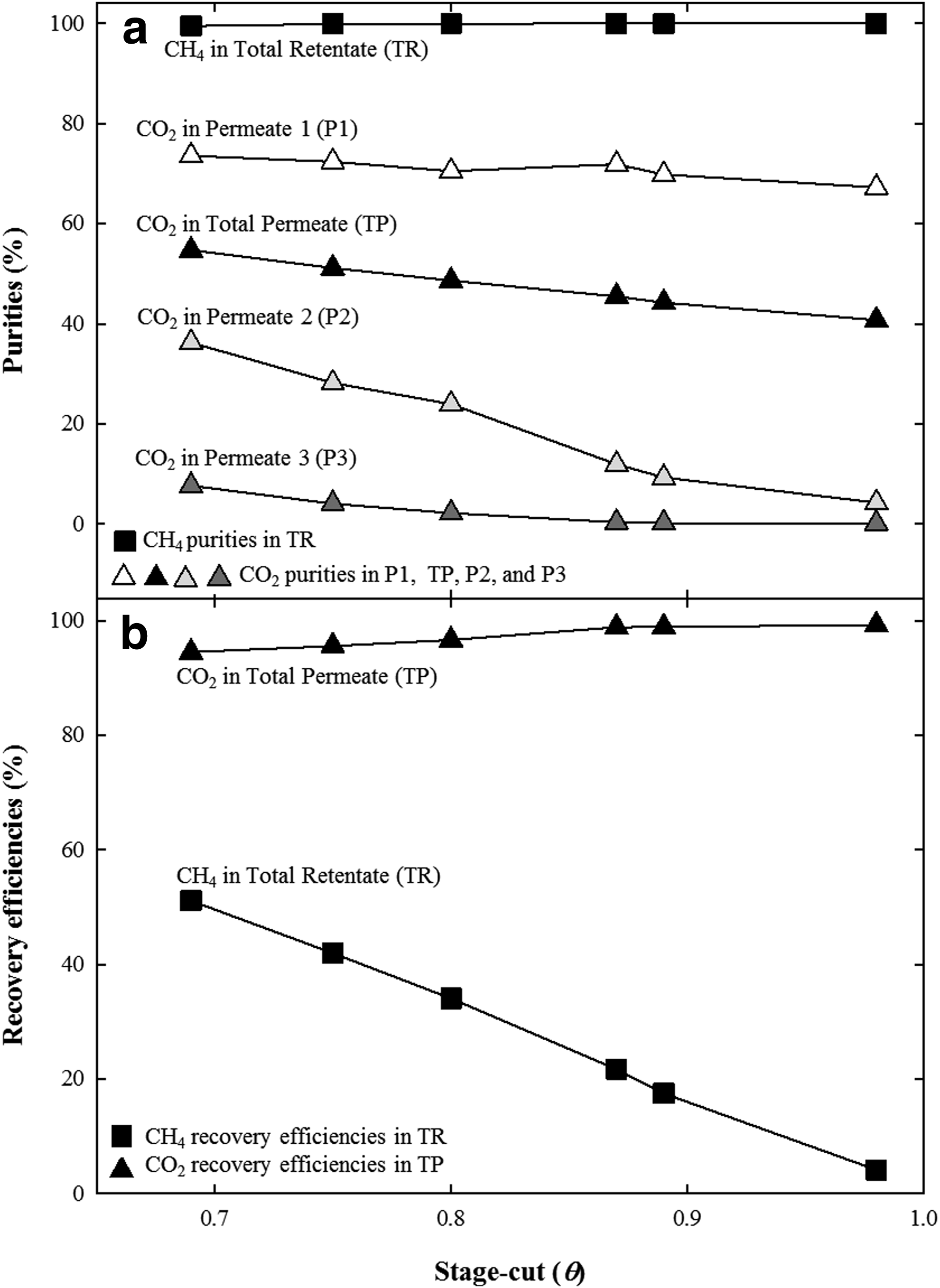
Separation performances of triple-stage permeation for CH4 recovery (Fig. 3e):
Measured CO2 purities were 67.2–73.6% in P1, 4.27–36.2% in P2, and 0.13–7.65% in P3, and the total CO2 purities in the permeate gases were 40.7–54.7%. The CO2 purities in permeate were too low to recover a large amount of CH4 in retentate, and substantial CH4 losses occurred since a low CO2 purity in the permeate gas indicates high concentration of CH4 in the permeate gas. In particular, the CO2 purity in the third module was so low that a large amount of >92% purity CH4 was wasted. Due to this reason, the CH4 recovery efficiency decreased; that is, the double-stage permeation was identified as being a more efficient module configuration than the triple-stage permeation, as the CH4 recovery efficiency was slightly higher at a similar CH4 purity.
Although CH4 was purified to >97.0% through double- and third-stage configurations, the recovery efficiency remained <71.2%. To improve the CH4 recovery efficiency, a triple-stage module configuration in which the permeate and retentate gas of the first stage were used as the feed for the second and third stages (Fig. 3f) was investigated (Fig. 9). The observed CH4 purities in R2 were 99.2–99.5% and the measured CH4 purities in R3 were >93.3% at stage-cuts >0.65, except for the 58.3% CH4 purity at stage-cut 0.50. The total CH4 purities improved to >97%, although the CH4 recovery efficiencies (24.1–57.2%) were not enhanced. Rather, the CH4 recovery efficiencies were similar to or slightly reduced compared to the double-stage permeation for CH4 recovery at similar CH4 purities.

Separation performances of triple-stage permeation for CH4 recovery (Fig. 3f):
Measured CO2 purities were 15.7–36.7% in P2 and 73.9–92.1% in P3. The CO2 purities in TP, estimated to be 44.6–64.9%, were lower than those of the double-stage permeation (Fig. 3d). As such, the CH4 recovery efficiency was found to decrease due to the emission of a large amount of CH4 through the permeate side. In contrast, the CO2 recovery efficiency remained excellent due to the recovery of high-purity CH4 from the retentate side. From these results, the recovery efficiency did not necessarily increase relative to the module configuration in which CH4 was recovered from the permeate gas during the first stage. An appropriate stage-cut control is recommended to further improve the recovery efficiency and purity. To improve the CH4 recovery efficiency, the emission of CH4 in the permeate side should be reduced by increasing the CO2 purity in the permeate gas. However, the results shown above indicate that high-purity CO2 in the permeate gas caused a corresponding decrease in the CH4 purity in the retentate gas, due to a trade-off (Robeson, 1991, 2008; Freeman, 1999).
A mixed triple-stage configuration, in which P1 and P2 were once again separated in the third module to extract CH4 (Fig. 3g), was also investigated (Fig. 10). Measured CH4 purities were 99.3–99.8% and 88.6–99.9% from R2 and R3, respectively. The retentate gas from the third module could be utilized individually due to its high CH4 purity. The CH4 recovery efficiency (65.6–88.9%) was the most improved, from among all configurations tested.
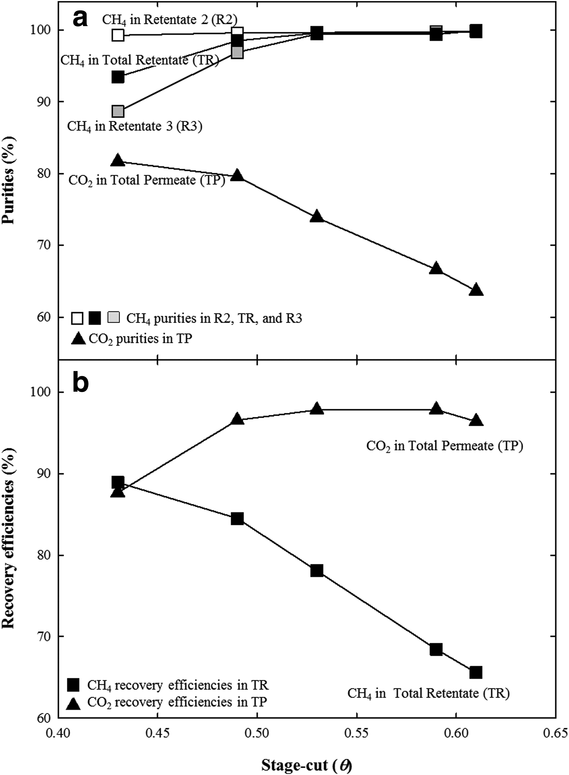
Separation performances of triple-stage permeation for CH4 recovery (Fig. 3g):
Emission of CH4 still occurred despite the additional separation of permeate gases. In this module configuration, the CH4 losses due to low CO2 purity in TP should be solved with the production of high-purity CO2 in TP by a decrease in the stage-cut. However, the CH4 purity in R3 should decrease with the recovery of high-purity CO2 in TP due to the trade-off (Robeson, 1991, 2008; Freeman, 1999). For this reason, CH4 purity in R3 significantly decreased at stage-cut between 0.43 and 0.49. Although CH4 purity and CH4 recovery efficiency concurrently increased in this configuration, the CH4 recovery efficiency was not close to 100%. Therefore, recycling the low-purity gases that were used as the feed in the first stage was required to produce high-purity CH4 at a high recovery efficiency.
Effect of recycling on separation performances
To enhance the CH4 recovery efficiency without decreasing the CH4 purity, the module configurations of Fig. 3d and f were modified into Fig. 3h and i, respectively, in which a recycling step was added. As the first change, the high-purity CH4 in P2 was recycled to the feed to increase the CH4 recovery efficiency without the need to install an additional module. The separation performances were then compared with or without recycling (Fig. 11a); the CH4 recovery efficiency with recycling increased by about 15%. Under this condition, the CH4 purity in TR was 97.0% regardless of recycling, because only the permeate gas was recycled. To further increase the CH4 recovery efficiency, high-purity CO2 should be produced in the first module. However, the increase in CH4 recovery efficiency obtained by recycling was limited since high-purity CO2 was not produced in the first stage. Therefore, to obtain high-purity CH4 at a high recovery efficiency, the module configuration requires that both CH4 and CO2 be produced with high purity.

Effect of recycling on the separation performance:
For this task, the low-purity gases in P2 and R3 in the Fig. 3f module configuration were recycled to the feed. The separation performances were then compared with and without recycling (Fig. 11b). The configuration of Fig. 3i was already a feasible concept (Brunetti et al., 2010). It is possible that the concurrent recovery of CH4 and CO2 is as follows. CH4 purity in TR and CO2 purity in TP increased to 99.2% and 92.1% from 85.0% to 64.9%, respectively. The CH4 and CO2 recovery efficiencies without recycling were 70.2% and 81.8%, respectively, whereas the recovery efficiencies with recycling were 96.4% and 99.7%. The recovery efficiencies of CH4 and CO2 were found to be dramatically improved. The reason the CH4 recovery efficiency was a little lower than the CO2 recovery efficiency was CH4 losses at P3 (92.1% CO2 purity). Therefore, almost all CH4 and CO2 in the biogas could be simultaneously recovered while producing high-purity CH4 and CO2 by using the module configuration shown in Fig. 3i.
Method to utilize biogas according to module configuration
Although biogas compositions may vary according to substrates, CH4 and CO2 are usually the largest components. CH4 in biogas has been utilized as an alternative fuel, while CO2 was considered as an impure component. However, the results of this study convincingly demonstrate that highly purified CH4 and CO2 can be recovered from biogas by using an appropriate module configuration. Now, let us discuss a method to effectively utilize biogas in terms of recovered resource utilization according to module configuration. Generally, >95% purity of CH4 is enough to use as biomethane (Petersson and Wellinger, 2009) and CHP can be operated using low methane such as landfill gas, which has 35% methane (Amiri et al., 2013).
First, the utilization of biogas can be improved by applying multistage configurations for CO2 recovery (Fig. 3b, c). Almost no CH4 loss was incurred and high-purity CO2 should be recovered through this module configurations. This high-purity CO2 can be used for a number of purposes, including as a growth enhancer in plants, food industry, and industrial processes, and the remainder, which contains >60% purity CH4, could be utilized as fuel for CHP (Fig. 12a). Alternatively, the retentate gas of the first module could be used to produce high-purity CH4 as fuel gas, since the CH4 purities of retentate gas in first-stage modules were as high as >90%, and this purity could be further enhanced (Fig. 12b). Then, the high-purity CO2 could be extracted from the final permeate gas, the remainder of which could be used as fuel for CHP or recycled into the feed gas to improve the recovery efficiency. In terms of increasing the energy efficiency, CHP was mentioned, but boiler is also applicable.

Methods to improve effective biogas utilization according to module configuration:
Serial module configurations for CH4 recovery (Fig. 3d, e, h) revealed that high-purity CH4 could be recovered, but too much CH4 was emitted (Fig. 12c, d). As such, by applying a recycling step, the CH4 recovery efficiency could be increased, but this increase was limited and CH4 losses occurred. In addition, the remaining gases were not appropriate for use as fuel for CHP operations because the CH4 purity was lower than in the feed gas. Therefore, even though high-purity CH4 could be produced and utilized as fuel for vehicles or grid injections, these module configurations were inefficient for effective biogas utilization due to the high CH4 loss rate and the difficulty in reusing the remaining gases.
Finally, we discussed mixed and recycled triple-module configurations (Fig. 3f, g, i), in which both high-purity CH4 and high-purity CO2 could be simultaneously produced. To enhance the recovery efficiencies of CH4 and CO2, the remaining gases should be recycled or used as fuel for CHP as they still contained abundant CH4. Therefore, the operation of this module configuration could vary according to the change in the resource demand. First, high-purity CH4 and CO2 could simultaneously be produced, and the remaining gases could be utilized for CHP operation (Fig. 12e). Alternatively, when CHP operation is not required, the remaining gas could be recycled as feed gas to enhance the recovery efficiency, thereby producing only high-purity CH4 and CO2 (Fig. 12g). When there is an increase in fuel required for CHP operation, due to increase in demand for electricity or heat energy, the retentate gas of first module could be directly utilized for CHP without producing biomethane by halting operation of the second module, or the stored biomethane could be utilized for CHP operation (Fig. 12f).
Module configurations capable of simultaneous recovery have the following benefits: (1) potential for low or zero carbon emissions, (2) reduced operational costs versus separate purchase of electricity, heat, cooling, and carbon dioxide, (3) uses all potential resources from gas utilization, (4) has a wide range of potential applications, and so on. However, even though this module configuration has a lot of advantages in term of energy efficiency, it requires a huge amount of building costs. Therefore, the best configuration will be changed depending on local situation. Hence, it is expected that biogas utilization can be maximized by modifying the module configuration according to the need for resources by members of the local community in which the biogas plant is installed.
Conclusions
For the effective utilization of biogas, membrane biogas separation experiments were performed with numerous module configurations, to determine an efficient way for utilizing biogas according to the module configuration. These findings can be summarized as follows:
(1) Single-stage permeation was not sufficient for recovering high-purity gas at a high recovery efficiency due to trade-off between the recovery of CH4 and CO2, as well as between the purity and recovery efficiencies. (2) Multistage permeation for CO2 recovery produced high-purity CO2 with minimal CH4 losses. High-purity CO2 could be utilized as a resource and the remaining gases, which had only slightly enhanced CH4 purity, could be utilized as fuel for CHP. (3) Serial-stage configuration for CH4 recovery produced high-purity CH4, although the efficiency substantially deteriorated. The CH4 recovery efficiency increased in conjunction with additional recycling steps, but CH4 losses still occurred. This high-purity CH4 could be utilized as fuel for vehicles or grid injections, although the use of remaining gases could be severely limited due to the reduction in CH4 purity. (4) A triple-stage permeation using retentate and permeate gases of the first stage as feed for the second and third stages could be used to simultaneously produce high-purity CH4 and CO2. By recycling the remaining gas, the loss rates for CH4 and CO2 dramatically decreased. Even if recycling was not applied, the CH4 purity in the remaining gas was high enough to use. Therefore, a variety of applications are possible with this module configuration.
The characteristics of CH4 and CO2 separated from biogas were changed with respect to the module configurations in terms of purity and recovery efficiency; accordingly, the resources obtained from the biogas varied.
Footnotes
Acknowledgments
This research was supported by “Korea Institute of Planning and Evaluation for Technology in Food, Agriculture, Forestry and Fisheries (IPET)” (project 312041-3) and by the 2013 sabbatical year research grant of the University of Seoul.
Author Disclosure Statement
No competing financial interests exist.
| Stage-cut | 0.89 | 0.64 | 0.41 | 0.32 | — | — | ||
| Purity (%) | CH4 in TR | 98.9 | 97.6 | 72.1 | 68.6 | — | — | |
| CO2 in TP | 44.4 | 60.6 | 78.1 | 83.1 | — | — | ||
| Recovery efficiency (%) | CH4 in TR | 18.2 | 58.5 | 70.8 | 77.6 | — | — | |
| CO2 in TP | 98.6 | 97.1 | 80.3 | 66.7 | — | — | ||
| Stage-cut | 0.31 | 0.29 | 0.24 | 0.21 | 0.14 | 0.07 | ||
| Purity (%) | CH4 in TR | 84.8 | 83.6 | 77.2 | 74.9 | 70.3 | 64.3 | |
| CH4 in R1 | 92.7 | 93.2 | 97.5 | 93.9 | 94.2 | 94.6 | ||
| CH4 in R2 | 64.5 | 62.1 | 53.1 | 45.3 | 38.7 | 32.7 | ||
| CO2 in TP | 94.2 | 94.4 | 94.7 | 95.1 | 95.9 | 97.5 | ||
| Recovery efficiency (%) | CH4 in TR | 97.8 | 98.3 | 97.9 | 98.7 | 100.5 | 99.4 | |
| CO2 in TP | 72.5 | 69.5 | 56.7 | 49.8 | 34.0 | 17.8 | ||
| Stage-cut | 0.31 | 0.29 | 0.27 | 0.26 | 0.22 | 0.07 | ||
| Purity (%) | CH4 in TR | 85.4 | 83.5 | 80.9 | 80.3 | 76.0 | 67.8 | |
| CH4 in R1 | 89.4 | 90.1 | 88.8 | 93.5 | 93.8 | 96.4 | ||
| CH4 in R2 | 88.2 | 87.9 | 88.3 | 76.1 | 75.9 | 61.1 | ||
| CH4 in R3 | 67.3 | 57.6 | 56.9 | 42.1 | 30.2 | 8.6 | ||
| CO2 in TP | 95.3 | 95.8 | 96.1 | 98.6 | 98.8 | 98.9 | ||
| Recovery efficiency (%) | CH4 in TR | 98.2 | 99.2 | 98.0 | 99.6 | 98.3 | 105.0 | |
| CO2 in TP | 73.9 | 68.7 | 65.7 | 62.9 | 55.3 | 17.4 | ||
| Stage-cut | 0.84 | 0.76 | 0.68 | 0.62 | 0.56 | 0.51 | ||
| Purity (%) | CH4 in TR | 100.0 | 100.0 | 99.7 | 99.1 | 97.0 | 94.6 | |
| CO2 in TP | 47.9 | 52.7 | 58.7 | 61.8 | 67.8 | 73.4 | ||
| CO2 in P1 | 64.2 | 68.2 | 72.1 | 75.5 | 77.6 | 81.8 | ||
| CO2 in P2 | 5.5 | 5.6 | 14.4 | 18.6 | 39.3 | 50.8 | ||
| Recovery efficiency (%) | CH4 in TR | 27.4 | 40.4 | 53.1 | 63.1 | 71.2 | 77.2 | |
| CO2 in TP | 99.9 | 99.8 | 99.8 | 95.5 | 94.8 | 93.7 | ||
| Stage-cut | 0.98 | 0.89 | 0.87 | 0.80 | 0.75 | 0.69 | ||
| Purity (%) | CH4 in TR | 100.0 | 100.0 | 100.0 | 100.0 | 99.9 | 99.5 | |
| CO2 in TP | 40.7 | 44.2 | 45.5 | 48.6 | 51.2 | 54.7 | ||
| CO2 in P1 | 67.2 | 69.8 | 71.9 | 70.5 | 72.4 | 73.6 | ||
| CO2 in P2 | 4.3 | 9.3 | 11.9 | 23.9 | 28.2 | 36.2 | ||
| CO2 in P3 | 0.1 | 0.2 | 0.3 | 2.2 | 4.1 | 7.7 | ||
| Recovery efficiency (%) | CH4 in TR | 4.1 | 17.5 | 21.7 | 34.1 | 42.0 | 51.2 | |
| CO2 in TP | 99.3 | 98.9 | 98.9 | 96.7 | 95.6 | 94.6 | ||
| Stage-cut | 0.85 | 0.81 | 0.76 | 0.65 | 0.50 | — | ||
| Purity (%) | CH4 in TR | 99.1 | 98.4 | 98.0 | 97.9 | 85.0 | — | |
| CH4 in R2 | 99.5 | 99.4 | 99.5 | 99.6 | 99.2 | — | ||
| CH4 in R3 | 98.9 | 97.5 | 96.1 | 93.3 | 58.3 | — | ||
| CO2 in TP | 44.6 | 47.7 | 51.0 | 59.2 | 64.9 | — | ||
| CO2 in P2 | 15.7 | 21.1 | 26.4 | 37.0 | 36.7 | — | ||
| CO2 in P3 | 73.9 | 76.1 | 78.3 | 82.7 | 92.1 | — | ||
| Recovery efficiency (%) | CH4 in TR | 24.05 | 31.09 | 38.62 | 57.19 | 70.19 | — | |
| CO2 in TP | 95.30 | 96.68 | 97.33 | 96.08 | 81.81 | — | ||
| Stage-cut | 0.61 | 0.59 | 0.53 | 0.49 | 0.43 | — | ||
| Purity (%) | CH4 in TR | 99.8 | 99.5 | 99.6 | 98.5 | 93.5 | — | |
| CH4 in R2 | 99.8 | 99.8 | 99.7 | 99.6 | 99.3 | — | ||
| CH4 in R3 | 99.9 | 99.4 | 99.5 | 96.9 | 88.6 | — | ||
| CO2 in TP | 63.7 | 66.6 | 73.9 | 79.6 | 81.7 | — | ||
| Recovery efficiency (%) | CH4 in TR | 65.6 | 68.5 | 78.1 | 84.5 | 88.9 | — | |
| CO2 in TP | 96.4 | 97.8 | 97.8 | 96.6 | 87.7 | — |
TP, total permeate gas; TR, total retentate gas.