




Abstract
Abstract
In water treatment, flocculation creates aggregated particles or flocs large enough to be removed by downstream processes of sedimentation and filtration. Fluidized beds of flocs (floc blankets) are sometimes included in upflow sedimentation processes because they can significantly improve sedimentation tank particle removal when plate or tube settlers are used. Overall performance of a sedimentation tank containing a floc blanket is influenced by the characteristics of incoming flocs from the flocculator. Floc blankets provide an additional opportunity for aggregation of colloidal particles that enables a reduction in the size of the flocculators, while improving particle removal efficiency. In this study, laminar flow flocculators varying in velocity gradient (G) and residence time (θ) were tested in a laboratory scale water treatment system with a floc blanket. Results indicate that increasing G (range of 74–251 s−1), while decreasing residence time from 269 to 80 s, and maintaining a constant Gθ (∼20,000) improved particle removal. These results indicate that velocity gradients greater than existing design recommendations may be used to reduce flocculator residence times (and associated construction costs) when upflow sedimentation with a floc blanket and overlying lamellar plate or tube settlers are employed subsequent to flocculation. Further reduction of the residence time to 24 s with a G of 251 s−1 resulted in a settled water turbidity of 14 nephelometric turbidity unit (NTU). When varying θ at a constant G of 72 s−1, an apparent minimum in settled effluent turbidity at 0.15 NTU was observed at the middle residence time tested (θ = 211 s), suggesting that long hydraulic flocculator residence times may be suboptimal.
Introduction
D
Small flocs can be produced by reducing flocculator hydraulic residence time (θ) so that flocs do not have time to grow very large, or through increasing fluid shear by increasing the velocity gradient (G) so that floc size is limited. Flocs formed under conditions of higher shear are smaller and thus more dense (Burban et al., 1989; Carissimi et al., 2007). However, excessively high shear produces very small flocs that may settle more slowly than the capture velocity of a sedimentation system resulting in an unacceptable performance (Garland et al., 2016). Thus, it is unclear how varying flocculator residence time and velocity gradient might beneficially change the floc blanket suspended solids concentration and the system performance as measured by settled effluent (or residual) turbidity.
Flocculator design is traditionally based on the product of G and θ, known as the Camp number (Gθ). Although G may only be appropriate for laminar flow conditions (Cleasby, 1984), it is conventionally used for design of turbulent flocculators. The flocculators used in this study were laminar flow and thus G is an appropriate parameter for the laboratory scale flocculator. Suggested values for Gθ for turbulent mechanically mixed flocculators range from 20,000–75,000, with G ranging from 20 to 75 s−1 (AWWA/ASCE, 2012; Gregory, 1979). It was not assumed that these parameters were directly applicable to a laminar flow tube flocculator, especially given the nonuniformity of the energy dissipation rate (EDR) in mechanically mixed flocculators (Bouyer et al., 2005).
Recommended minimum residence time for flocculators varies from 10 min (AWWA/ASCE, 2012) to 30 min (Great Lakes—Upper Mississippi River Board of State and Provincial Public Health and Environmental Managers, 2012). It is likely that guidelines for flocculator G and θ were developed based, in part, on the experience where a low Peclet number mechanically mixed flocculator was followed by a conventional horizontal flow sedimentation tank. The applicability of these guidelines is uncertain in cases where a high Peclet number hydraulic flocculator (Weber-Shirk and Lion, 2010) is followed by an upflow sedimentation tank with a floc blanket and lamellar sedimentation.
Smaller flocculators use fewer materials and cover a smaller area, reducing the overall cost of the plant. Given the conventional design criterion for Gθ, increasing G would mean a subsequent decrease in θ to maintain constant Gθ. In the laminar regime, G scales with the square root of the average EDR,
In this research, experiments were conducted to determine the impact of flocculator design on a laboratory-scale water treatment plant with a flocculator, a floc blanket, and tube settlers. Seven alternative flocculator designs were compared: three flocculators with the same Gθ and different G and θ values; three flocculators with the same G, but increasing θ; and one flocculator with a high G and low θ.
Experimental Protocol
The laboratory-scale experimental apparatus was the same as described by Hurst, et al. (2014) with the exception that a floc weir was used to limit floc blanket height, and almost all influent fluid was removed from the reactor by passage through tube settlers. A schematic of the apparatus is provided in Fig. 1. The height of the floc weir was 86 cm from the bottom of the jet reverser. Velocity of water through the jet reverser was 1.6 m/s. Angle of the bottom slope is 45° and diameter of the round inlet jet tube was 4.6 mm. Aerated tap water (average pH 7.36, total alkalinity 131 mg/L as CaCO3, total hardness 150 mg/L as CaCO3, dissolved organic carbon 1.83 mg/L) (City of Ithaca, 2014) was mixed with an 8 g/L stock kaolinite clay suspension (R.T. Vanderbilt Co., Inc. Norwalk, CT.) to form a 100 nephelometric turbidity unit (NTU) synthetic raw feed water. To maintain a steady influent suspended solids concentration, an inline turbidity meter monitored the turbidity (HF Scientific Microtol Inline Turbidity Meter, Range: 0–1,000 NTU) and Proportional Integral Derivative control implemented with Process Control and Data Acquisition (ProCoDA, 2015) software was used to meter the clay stock. Polyaluminum chloride (PACl; PCH-180 Holland Co., Adams, MA) was mixed to create a stock 567 mg/L as Al and added to the influent stream using a peristaltic pump (Cole Parmer MasterFlex L/S, 1.6–100 RPM Peristaltic Pump). The flow rate of the pump was adjusted to obtain a PACl dose of 1.25 mg/L as Al. Effluent turbidity was measured with an inline turbidity meter (HF Scientific Microtol Inline Turbidity Meter, Range: 0–1,000 NTU) after the tube settlers and recorded every 5 s for the duration of each experiment. Floc blanket concentration measurements were made through digital image analysis of light absorbance as described by Hurst et al. (2014). Images were acquired at 60-second intervals with a Basler (Basler, Ahrensburg, Germany) color SCA640-70FC IEEE-1394B camera (658 × 490 pixels) using an 8 mm lens. Image field of view was 98.9 × 73.5 cm. Images for the floc blanket solids concentration region (see region indicated in Fig. 1) were processed postexperiment to obtain suspended solids concentrations using LabVIEW software.

Design schematic of experimental apparatus. Influent to the sedimentation tank from the flocculator entered through a tube directed downward into the jet reverser. The flow was redirected upward by the semicircular jet reverser. The region of interest utilized for image analysis of floc blanket suspended solids concentrations is indicated with dashed lines. Ten percent of the total flow was sent to waste because it was insufficient to support an additional tube settler. Items in the shaded region indicate the postflocculator processes (i.e., the floc blanket plus tube settlers) considered in the sedimentation tank. PACl, polyaluminum chloride.
Performance of the system comprised of a flocculator, sedimentation tank, and tube settlers with no floc blanket was determined using the effluent turbidity after one full hydraulic residence time of the flocculator, sedimentation tank, and tube settlers. The beginning of steady state was defined as when the floc blanket height reached the top of the floc weir and the floc blanket concentration was constant within ±2.5% of the mean concentration over the residence time of fluid in the floc blanket. After steady state was reached, data were averaged for one hydraulic residence time of the sedimentation tank (8.3 min) to obtain steady state floc blanket concentration and effluent turbidity.
In a typical water treatment process train, a filter would follow sedimentation and, assuming 90% particle removal through filtration, the highest turbidity that could be sent to the filter and still produce a final effluent turbidity at or below EPA standards would be 3 NTU. Thus, settled effluent turbidity ≥3 NTU was adopted as criterion for failure of the upstream flocculator/floc blanket/tube settler system. The time required to form each floc blanket was also noted and Gθ combinations that resulted in long formation times are considered undesirable.
Six tube settlers with a capture velocity (also referred to as a critical velocity) of 0.1 mm/s were utilized for this experiment. Tubes were 1 in. PVC with a flow rate of 0.9 mL/s (per tube) set at 60°from the horizontal. The flocculator EDR was altered by changing the diameter of the flocculator tubing and the flocculator hydraulic residence time was adjusted by changing the length of tubing. Energy dissipated in the flocculator was determined by first calculating the major head loss due to laminar flow through the same length of straight tube using the Hagen–Poiseuille equation,
where ν is the kinematic viscosity of water—1.0 mm2/s at 20°C, L is the length of the flocculator, Q is the flow rate, and
Total energy losses accrued (including losses caused by the curvature of the helically coiled flocculator,
where hf is the major head loss from Equation (1),
where θ is the hydraulic residence time of the flocculator.
Average velocity gradient, G, was calculated as follows:
Characteristics of the experimental flocculators are summarized in Table 1. Replicate experiments were performed for each Gθ combination.
Values are averages of two experiments.
Major head loss was measured for flocculator 2 (G = 126 s−1, θ = 159 s) to verify calculations. Theoretical head loss was calculated to be 27.8 cm using Equations (1) and (2) and actual head loss was measured with a pressure sensor to be 26.2 cm. Due to coagulant and clay to the walls, head loss increased with run time. Approximately 0.7% of influent was lost to flocculator walls and head loss increased at a mean rate of 10.4 mm/hr during experiments. Consequently, in all flocculators, final G was higher than initial flocculator G.
EDR through the floc blanket is a function of the solids concentration within the floc blanket and was calculated as follows (Hurst et al., 2010):
where VUp is the upflow velocity of the sedimentation tank, CS is the suspended solids concentration of the floc blanket, Φ is the porosity of the floc blanket (85% based on settling tests), and
Results
An example of all data collected for an experiment is presented in Fig. 2. A summary of steady-state floc blanket concentration and effluent turbidities can be found in Table 2.

Example of floc blanket suspended solids concentration and effluent turbidity over time through an experiment (G = 72 s−1, θ = 211 s). Effluent turbidity is plotted on the secondary y-axis. The total length of time used for averaging both steady-state and no floc blanket performance is 150 s.
Values are averages of two experiments.
NTU, nephelometric turbidity unit.
Maintaining a constant Gθ and varying G
The velocity gradient, G, of the flocculator was changed, while maintaining a constant Gθ of ∼20,000. Flocculators with G values of 74, 126, and 251 s−1 (EDR of 5.5, 16, and 63 mW/kg, respectively) were utilized with simulated raw water of 100 NTU and PACl dose of 1.25 mg/L as Al. Floc blanket suspended solids concentrations increased slightly with the higher flocculator G, while tube settler turbidity decreased with a higher flocculator G (Fig. 3). The effluent turbidity of the two flocculators with the lower G values was on the borderline of failure.

Steady-state average suspended solids concentrations in the floc blanket and effluent turbidity at flocculator G values 74, 126, and 251 s−1 and constant Gθ ≈ 20,000. Effluent turbidity points correspond to the secondary y-axis. Error bars indicate the standard deviation of each experiment; however, they are about the same size of the point symbol in many cases. Replicates are shown for each experiment.
Effluent turbidity without a floc blanket was not significantly different across experiments (Fig. 4). Based on the difference in performance with and without a floc blanket, the highest G experiment demonstrated the largest improvement and the best performance when the floc blanket had formed. The lower and intermediate G experiments also improved with the presence of a floc blanket.
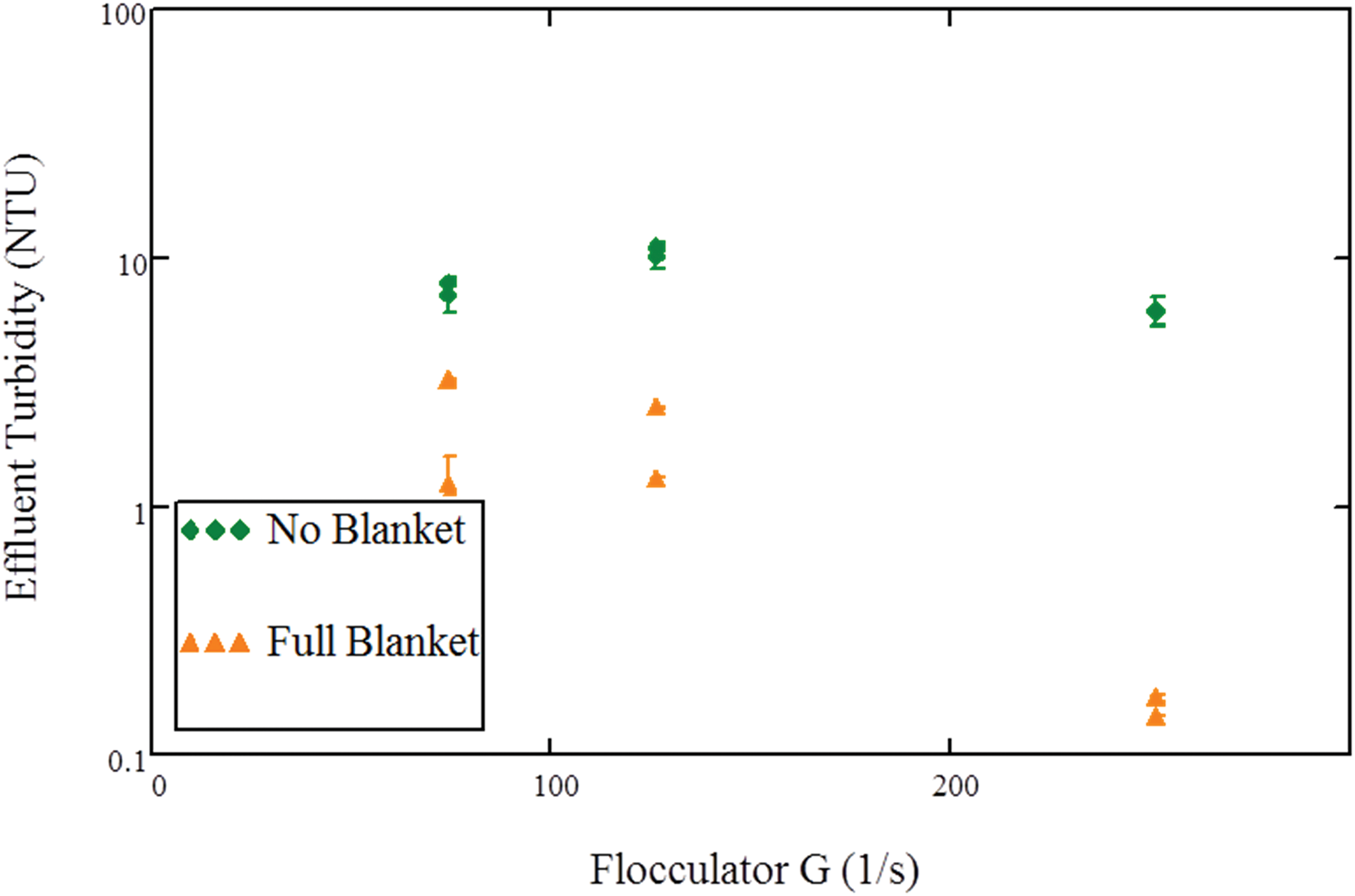
System performance with and without a floc blanket for experiments with increasing G and constant Gθ. Error bars are shown; however, they are about the same size of the point symbol in many cases. Replicates are shown for each experiment.
Changing flocculator residence time
Experiments were conducted holding flocculator G constant (72 s−1 and close to the lowest G value tested at constant Gθ) and changing θ (24, 211 and 1,425 s). As flocculator residence time increased, the floc blanket suspended solids concentration decreased (Fig. 5). Floc blanket suspended solids concentration for the longest residence time averaged 2,100 mg/L and increased to 4,500 mg/L for the shortest residence time. Effluent turbidity reached minimum values at the intermediate 211 s residence time.
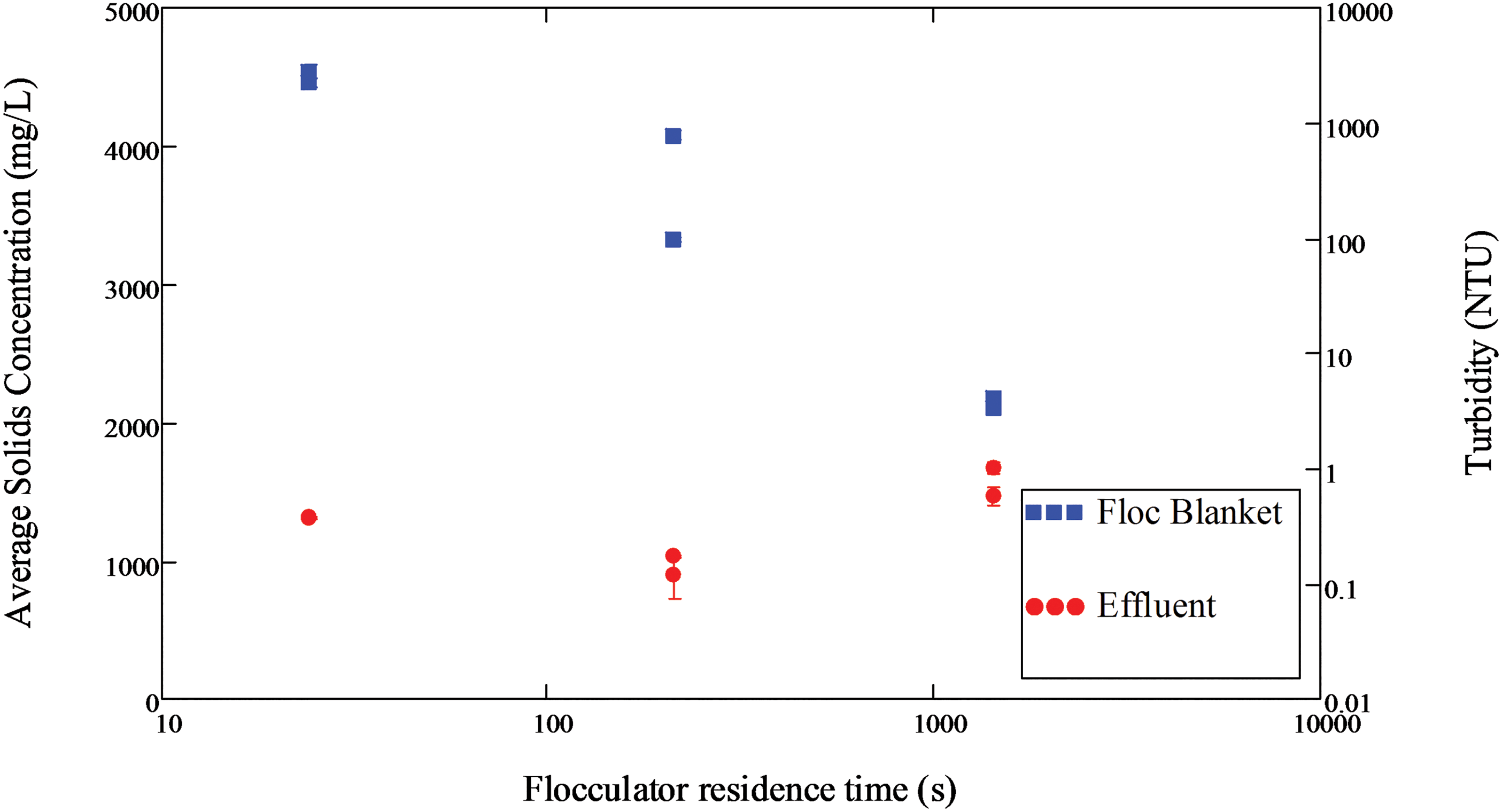
Steady-state average system concentrations at G = 72 s−1 and varying flocculator residence time. Error bars are shown; however, they are about the same size of the point symbol in many cases. Replicates are shown for each experiment.
Effluent turbidity without a floc blanket was highest for the lowest residence time flocculator and very similar at higher residence times (Fig. 6). As the residence time of the flocculator increased, the contribution of the floc blanket to solids removal tended to decrease.

System concentrations with and without a floc blanket for experiments with increasing θ and constant G (72 s−1). Error bars are shown; however, they are about the same size of the point symbol in many cases. Replicates are shown for each experiment.
Given that the lowest residence time flocculator (G = 72 s−1) had a higher effluent turbidity than other experiments with similar G (Fig. 5) and higher flocculator G values produced lower effluent turbidity (Fig. 3), it was expected that increasing flocculator G, while maintaining the residence time, might improve system performance. Figure 7 shows the results of the high G (251 s−1), low θ (24 s) experiment alongside the low G (72 s−1), low θ experiment in Fig. 4, which produced high effluent turbidity. Both floc blanket concentration and effluent turbidity increased with the higher G flocculator. Effluent turbidity averaged 14.3 NTU for both experiments, indicating that the system was in failure with this flocculator.
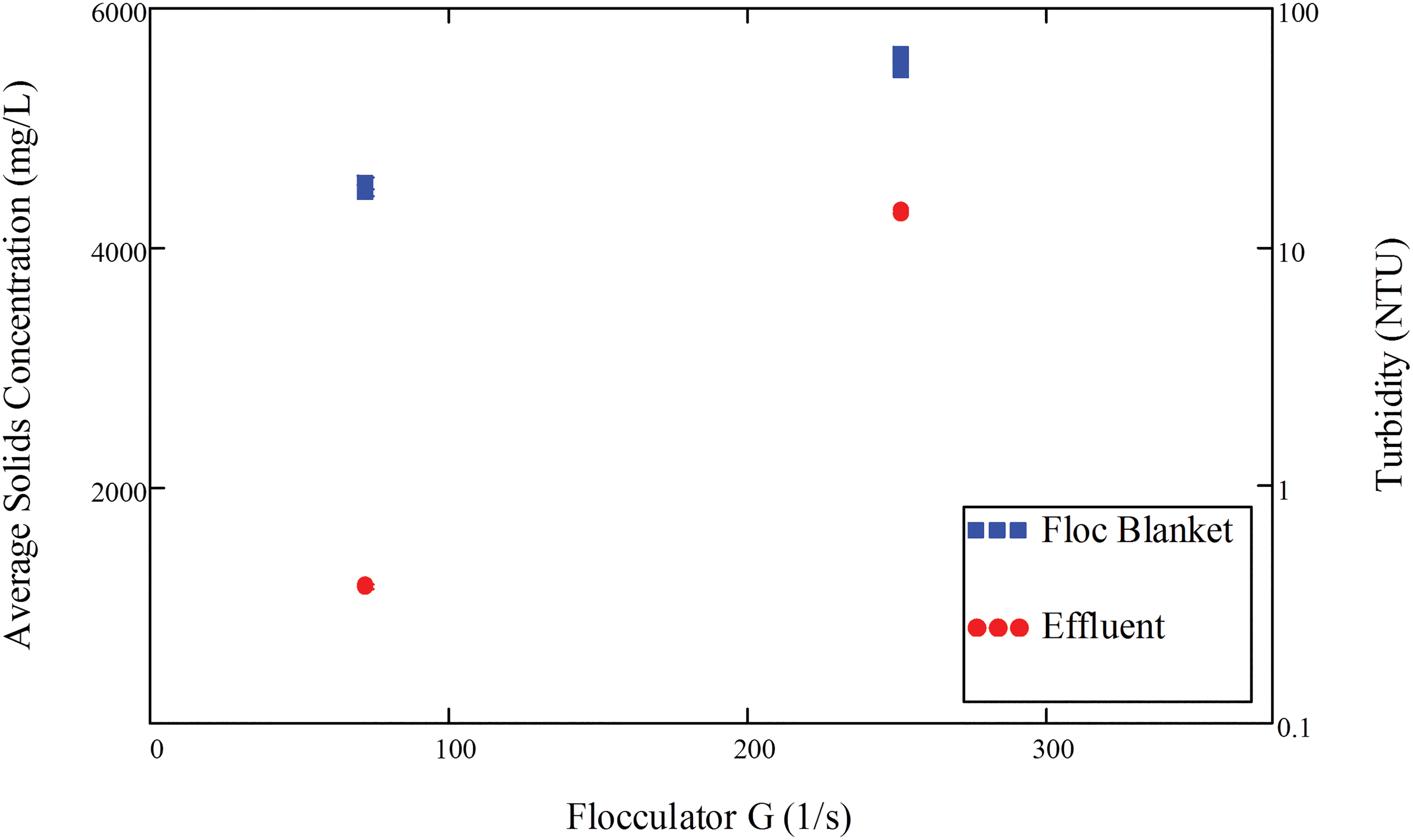
Steady-state average system concentrations at low (72 s−1) and high G (251 s−1) and constant flocculator residence time. Error bars are shown; however, they are about the same size of the point symbol in many cases. Replicates are shown for each experiment.
Discussion
Flocculators and floc blanket concentrations
Increasing the velocity gradient of the flocculator would be expected to produce smaller flocs as floc size scales inversely with shear (Parker et al., 1972; Spicer and Pratsinis, 1996; Jarvis et al., 2005). Generally, small flocs produce higher floc blanket concentrations (Su et al., 2004; Bache, 2010; Hurst et al., 2010). Higher floc blanket suspended solids concentrations were observed with higher G flocculators and low residence time flocculators supporting expectations that smaller flocs were produced from these conditions. In the case of the short residence time flocculator, floc size was likely set by insufficient opportunity for particle collisions.
A floc resulting from a collision between a small and large floc (particle to cluster aggregation) will have a higher mass fractal dimension with a higher density than the original large floc (Gregory, 1997). In addition, flocs formed in high G conditions were observed by Jung et al. (1996) to be more compact and had a higher fractal dimension. We hypothesize that the collisions between small flocs coming from the flocculator and large fully grown flocs in the floc blanket produce flocs with a higher mass fractal dimension, increasing the floc density and thus the solids concentration. As flocs enter the floc blanket where shear is much lower than that in the flocculator (GFB = 4.4–6.4 s−1 for floc blankets produced in these experiments calculated by Equation (6); flocculator G's of 72–251 s−1), they will grow in size until the shear in the floc blanket prevents further growth. As small flocs enter the floc blanket from the flocculator, they collide with large floc blanket flocs resulting in a floc with increased density and fractal dimension. As a result, flocculators that produce a large number of small flocs (high G or low residence time flocculators) are expected to produce higher concentration floc blankets.
Li and Logan (1997) looked at collision efficiencies between fractal aggregates and colloids and concluded that colloid removal efficiencies were related to the porosity of the fractal. Larger, more porous flocs were seen to be more permeable allowing water to flow through them achieving rectilinear fluid motion and capture of small colloids. As the large porous flocs accumulated colloids and floc porosity decreased, water would tend to travel around the fractal aggregate (curvilinear motion) and decrease colloid capture. This observation also suggests that floc blanket flocs may have a limited capacity for collisions with small particles and finite capacity for particle to cluster aggregation. In the case of a floc blanket, dense flocs resulting from particle to cluster aggregation would remain fluidized and increase the suspended solids concentration as well as coupled EDR (and thus number of collisions of small like-sized particles) in the floc blanket. Thus, small particle removal may occur through a combination of particle-to-cluster aggregation (creating dense flocs and a higher floc blanket suspended solids concentration) and increased like-sized small floc collisions promoted by the ensuing higher EDR in the floc blanket. Tambo and Hozumi (1979) modeled contact flocculation under the assumption that only collisions between grown flocs and small flocs were significant. The basis for this assumption was directed at modeling the number of small flocs removed in the fluidized bed; however, the assumption is as relevant to understanding the increase in floc blanket suspended solids concentration as it is to what collisions are significant.
The flocculator with lowest G (and longest residence time) created the least concentrated floc blanket (Fig. 5). Flocs from this flocculator would have been the largest due to the low G, and the number of small flocs would have been minimized due to the long residence time. As a result, it is expected that there would have been very few small flocs to collide with floc blanket flocs to increase the overall suspended solids concentration. This reasoning is consistent with the low floc blanket solids concentrations observed in the low G, long θ experiment.
Potential for collisions in the floc blanket
The mechanism by which the floc blanket improves system performance in terms of settled water turbidity is thought to be removal of small flocs through flocculation (collisions between small flocs) and/or filtration (collisions between small and grown flocs). Higher floc blanket suspended solids concentrations would be expected to have better removal because the distance a floc must travel before colliding with another floc is small compared to a lower concentration floc blanket. Higher shear in the floc blanket at high suspended solids concentration would also increase the number of small floc collisions occurring in the floc blanket. The overall performance of a floc blanket is controlled by the removal of small flocs that would otherwise escape the tube settlers. Growing flocs to the largest possible size is not the operational goal; instead it is to ensure the smallest flocs grow to be large enough to be captured by the tube settlers. Thus, floc blanket design should encourage collisions with the smallest flocs to reduce effluent turbidity. This can be achieved with higher floc blanket suspended solids concentrations that create higher shear and hence more collisions between small flocs and between small and grown floc blanket flocs.
In experiments where G was varied, but Gθ remained the same (Figs. 3 and 4), the two highest G flocculators produced blankets with very similar suspended solids concentrations, but notably different effluent turbidities (0.15 NTU at G = 251 s−1 and 1.9 NTU at G = 126 s−1). Given the high suspended solids concentration of the floc blanket and smaller size of flocs exiting from the highest G flocculator, it is possible that this Gθ combination represents an optimal condition where the floc blanket suspended solids concentration is high, increasing collisions, and the flocs from the flocculator are small so that the smallest flocs, which would have otherwise escaped the tube settlers, grow to a size that can be captured. When the same flocculator G with lower residence time was used, effluent turbidity was very high (14.3 NTU) even though the floc blanket suspended solids concentration was high (Fig. 7). Poor performance in this case was likely the result of too many small flocs with sedimentation velocities less than the capture velocity of the tube settlers. Although some of these flocs were undoubtedly captured in the floc blanket, too many of them escaped and were not able to be captured by the tube settlers.
The lowest suspended solids concentration floc blanket was created by the low G, long θ flocculator (Fig. 5). Interestingly, the effluent turbidity of the system without a floc blanket in this case (Fig. 6) was very similar to those for the intermediate θ flocculators suggesting that flocs leaving both flocculators were similar in overall size and had settling velocities higher than the capture velocity of the tube settlers. In Fig. 5, it is apparent that there was a minimum steady-state effluent turbidity at the intermediate residence time. Although the research presented in this study does not reveal the optimal residence time producing the lowest effluent turbidity, it is important to note that additional θ was not helpful, but in fact reduced system performance with a floc blanket.
Practical considerations
In practice, it takes time for a floc blanket to form and the high effluent turbidity during this interval is an important consideration. From experiments with constant Gθ, the low and high G flocculators had lower formation times relative to the intermediate G flocculator (Table 1), but all produced a higher effluent turbidity without a floc blanket (Fig. 4). From the experiments with varying flocculator θ, the intermediate and longest θ had reasonable effluent turbidity without a floc blanket (Fig. 6) and formation times relative to the flocculator with the lowest θ (Table 1). For all cases tested, the formation time was generally longer in flocculators that produced poor effluent turbidity without a blanket during startup or during steady-state operation. System performance would decrease in all cases if the tube settler capture velocity was increased and must be accounted for in system designs.
The results presented in this article indicate that flocculator design can influence floc blanket suspended solids concentration and effluent turbidity. Some decrease in flocculator hydraulic residence time (and coupled construction costs) may be accomplished through the use of higher G. However, direct use of Gθ based on the results presented above where the experimental flow was laminar should not be applied for system design for turbulent flocculators or flocculators with high temporal and spatial variability in EDR. Hydraulic flocculation research under conditions of turbulence is needed to better define the tradeoff between hydraulic residence time and the EDR.
Summaries
The research presented in this article shows that the current guidelines do not produce optimal results when a floc blanket is used. At constant Gθ, the lowest velocity gradient tested (and the highest suggested by design guidelines) performed the worst (Fig. 3) and the lowest settled effluent turbidity was observed at the highest velocity gradient tested. In experiments with constant G and varying θ, there was an apparent minimum in effluent turbidity (Fig. 5) where an increase in θ did not improve turbidity removal. Over the 62-fold reduction in experimental flocculator residence time tested (from 1,425 to 24 s), the effluent turbidity increased by about 0.43 NTU suggesting that smaller flocculator could be used in series with a floc blanket.
Flocculators used in this article created a range of floc blanket concentrations (2,100–5,500 mg/L) when a constant PACl dose was used. Previous research has strongly suggested that higher floc blanket concentrations are related to better floc blanket performance (Gregory et al., 1996; Hurst et al., 2010); thus it might be possible to improve performance of a water treatment plant by designing a flocculator that will produce a high concentration floc blanket.
Experimental results suggest that, within reasonable limits, hydraulic flocculators with residence times that are shorter than recommended limits and velocity gradients above recommended limits might be a means to improve performance assuming a floc blanket and lamellar sedimentation are employed. Design of a water treatment plant has never been optimized for cost and/or performance, and these results suggest that flocculators could be smaller, and likely less expensive, in optimized designs. Smaller flocculators use fewer materials and require less area to build. These results may be more directly applicable to hydraulic flocculators designed to have a more uniform EDR as opposed to mechanical flocculators with a large difference between maximum and average EDR. Further research is needed to understand how flocculator design, suspension properties, and coagulant dose control floc size distributions and subsequent particle capture by floc blankets and lamellar sedimentation.
Footnotes
Acknowledgment
This research was supported, in part, by National Science Foundation award ID 1437961.
Author Disclosure Statement
No competing financial interests exist.