
Abstract
Abstract
The working principle and operating characteristics of a decontamination tower with sieve trays, when used to wash radioactive droplets entrained by the vapor from a wastewater evaporation unit of nuclear power plants, were analyzed and the mixing and dilution mechanism for washing radioactive droplets presented. Based on results and proposed mechanism, a simple but useful engineering model was developed to describe the relationship of decontamination factor (DF) with the sieve tray number, entrainment rate in vapor, reflux ratio, and demister efficiency, as well as the mixing degree of the entrained droplets with the reflux distillate on the trays. Quantitative analysis indicates that this model can show how these factors affect the decontamination efficiency of the tower and thus can be used as an analytical tool for operation or design of the decontamination towers. Following the proposed model, a step-by-step design procedure is presented for calculating the required sieve tray number under the designated DF value. Finally, for the requirement and condition of boron recycle system, a decontamination tower was designed using the proposed model and procedure, and a pilot-scale test verified that the tower can achieve the design DF. Based on the pilot test, a plant-scale prototype tower has been designed and successfully put into use in the Hong Yanhe Nuclear Power Plant in China. The design practice indicates that this model, as a simple but useful tool, can also be applied to the operation analysis and the design of other sieve tray towers operating in similar cases.
Introduction
W
In the evaporation process, the entrainment of radioactive droplets with vapor stream is inevitable, which contaminates the condensate and thus reduces the DF. Hence high-efficiency vapor–liquid separation is necessary to obtain the desired clean distillate. Over past decades, many de-entrainment apparatus have been used to assist the process of vapor–liquid separation so as to obtain a higher DF, such as cyclone, wire mesh demister, and packed or plate column (Yamomoto, 1968; IAEA, 1984).
Schlea and Walsh (1961) experimentally studied the de-entrainment effectiveness of plate column with various caps. They found that more plates can achieve less entrainment rate, and the impingement-cap tray has a higher removal efficiency of entrainment than the bubble-cap tray. However, they did not consider the variation of salt concentration in liquid droplets and the relationship of DF with reflux ratio and plate number. International Atomic Energy Agency (1984) has reported a pot-type evaporator with Raschig rings, which can achieve the DF of over 105 or more in treating radioactive waste liquid. Unfortunately, there is no more specific information reported about its design and performance. Lee et al. (1986) investigated the de-entrainment of boron for the evaporator used in nuclear power plants. Their experimental results showed that the de-entrainment efficiency of glass wool packed column is significantly higher than that of the cyclone, besides the combination of the cyclone and glass wool packed column can provide overall DF of more than 103. Lee and Lee (1993) described a forced circulation evaporation system of Kori Nuclear Power Plant in Korea, in which a sieve tray column was used to wash the vapor. They pointed out that vapor velocity in the column affects the DF greatly, and sieve trays can decrease entrainment due to more sufficient disengaging space. However, they did not quantitatively analyze the effects of these factors on the DF. Ma et al. (2014) reported a natural circulation evaporator integrated with bubble-cap trays and mist eliminator for the treatment of radioactive waste liquid, but did not report their design thought and method.
These previous studies have shown that plate tower is effective and most used equipment for the de-entrainment of droplets from vapor stream. However, they did not explain why the plate tower should be used. In addition, they commonly consider that the function of sieve trays is to intercept or separate the droplets from vapor stream, but this is not the case since even dry air will entrain the droplets after it flows through sieve trays, indicating that the other mechanism exists in the process. Therefore, from these previous studies, the DF cannot be correlated with the treated amount of vapor, entrainment rate, sieve tray number, reflux ratio, demister efficiency, and so on.
In this article, the working principle and operational characteristics of a decontamination tower used for washing the vapor with radioactive droplets at pressurized water reactor (PWR) nuclear power plants were analyzed. According to the analysis results, the mixing mechanism of the entrained droplets with reflux distillate on sieve trays was proposed, and then a simple but useful engineering model is developed to quantitatively describe the washing process and the relationship between the DF and sieve tray number. Moreover, all main factors affecting the DF have been discussed based on the model. The results provide a theoretical guidance for how to improve the DF of a decontamination tower. Furthermore, for the purpose of engineering design, a step-by-step procedure is presented for calculating the theoretical tray number corresponding to the designated DF value. Finally, this procedure has been successfully applied to the design of two decontamination towers. One is a pilot-scale unit and the other is an industry unit, which currently has been put into use in Hong Yanhe Nuclear Power Plant in China.
Operation and Features of the Decontamination Tower
For the washing of vapor with contaminated droplets, the sieve tray tower becomes preferred because it can achieve high efficiency by using less water and increasing the tray number. This is particularly true in the treatment system of radioactive water by evaporation method, where the washing water, usually called reflux, must be returned to the evaporator to revaporize, and more washing water used means more energy consumption.
Figure 1 shows a decontamination tower with sieve trays, which has been used in the evaporation unit to wash the secondary vapor in a nuclear power plant of China. In operation, vapor with radioactive droplets enters into tower from the bottom and then flows up through each tray where the vapor contacts with the reflux. The washed vapor from the top tray will go through a wire demister to remove part of droplets and finally exits out of the tower. Thereafter, the vapor will be condensed into condensate in a condenser.
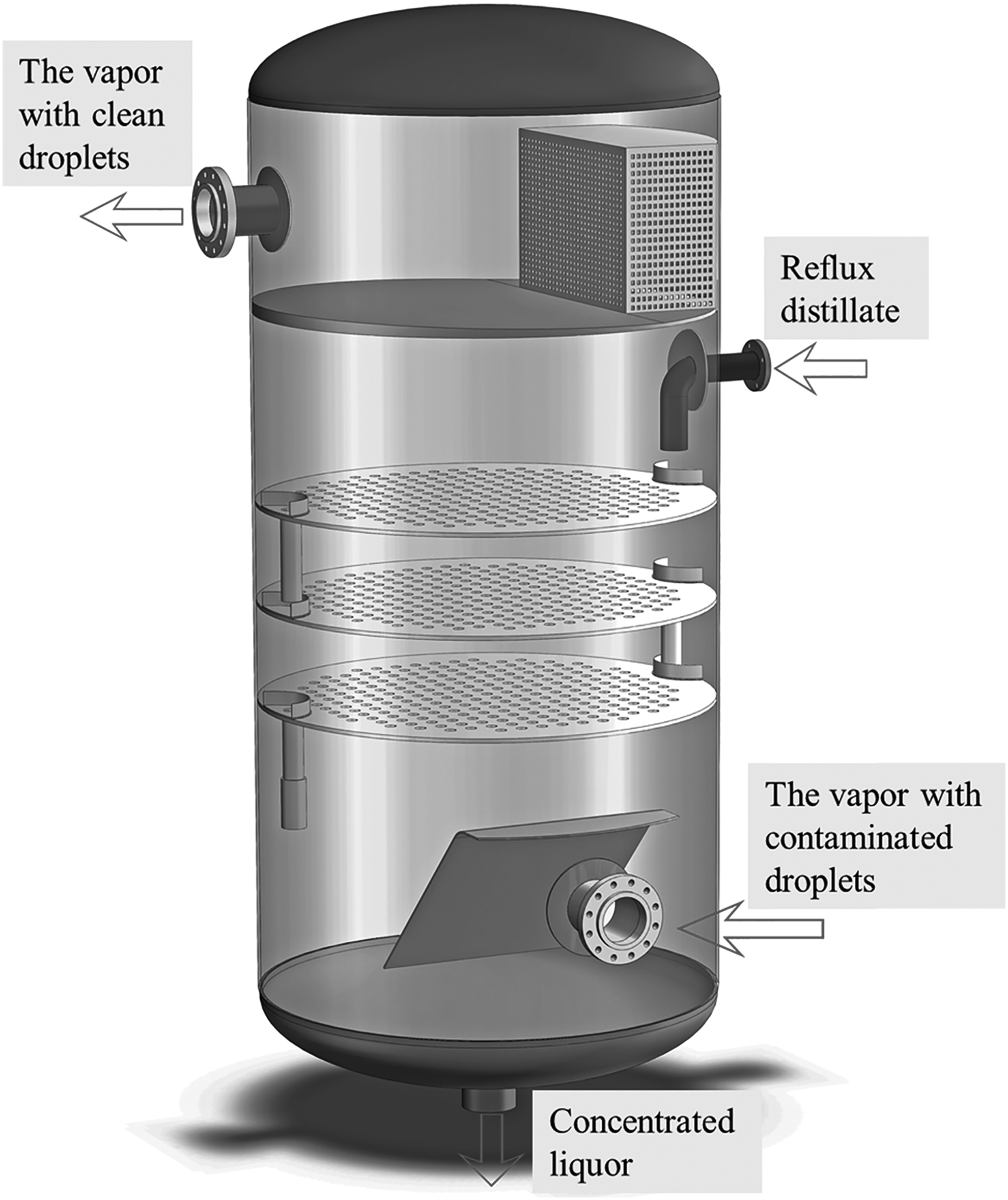
Decontamination tower with three sieve trays.
Obviously, the more the number of trays there are, the more the number of washing iterations are. As a consequence, the DF of the decontamination tower is determined by its tray number. However, the mechanism of washing process is different from that of the mass transfer process, such as absorption or desorption process in a traditional sieve tray tower. In the washing process by using the decontamination tower, vapor-entrained droplets of high radioactive concentration will be intercepted by and mixed with the reflux distillate of lower concentration on the tray, and therefore when the vapor leaves the tray, the re-entrained droplets by vapor will be the renewed droplets of lower concentration. This process repeats on every tray and the droplet concentration becomes lower and lower, until it reaches the designed value after some tray.
The decontamination tower also has some characteristics in operation. As mentioned above, in the treatment system of radioactive water by evaporation method, reflux used in the washing process must be returned to the evaporator to revaporize, so it is desired for the amount of reflux to be as less as possible under a given DF value so that energy consumption used for evaporation stays within a reasonable limit. Furthermore, to reduce the amount of vapor condensed by the reflux, it is also desired for the reflux to have a temperature close to the vapor temperature. Therefore, in common practice, the distillate having a temperature close to vapor temperature is used as reflux, and the mass flow rate of reflux is only 5%–10% of the rising vapor (Yamomoto, 1968; Ma et al., 2014). In this way, the latent heat released by condensation of only small amount of vapor is enough to heat the reflux distillate to the saturated state at the reflux inlet section (the top tray) so that the vapor and liquid phases below the top tray are operated in a saturated state.
Process Model
Basic descriptions
To develop the process model of the decontamination tower, the following assumptions can be made based on the discussions above:
(1) To include a more general case, the mixing between droplet and reflux on the tray is considered as a partial mixing process. Define a mixing degree factor as α, 0 < α ≤1, to characterize the mixing degree of the droplets with the reflux. The larger the value of α is, the more sufficient the mixing is. If the droplets are completely mixed with reflux distillate, or for perfect mixing, α = 1. (2) Since the amount of reflux liquid is small, only a small amount of secondary vapor condenses at the top tray to heat the reflux to the saturated state. The vapor and liquid phases below the top tray are operated in a saturated state, thus mass flow rate of the vapor stays constant below the top tray in the tower. (3) The washing process in the decontamination tower is in a steady-state operation, and the radioactive component is nonvolatile material.
Mass balance models for decontamination tower
The flows of vapor and reflux in the decontamination tower are shown in Fig. 2, the evaporation chamber is included to consider a more general case. In this figure, the symbols G and L are used for the mass flow rates of vapor and liquid (reflux distillate and liquid feed), e is the mass flow rate of the entrained droplets, x denotes the mass fraction of radioactive component in liquids (droplets, distillate, and feed liquid), and β denotes the interception efficiency of droplet in wire mesh demister (0 ≤ β ≤ 1).

Flowchart in decontamination tower.
As shown in Fig. 2, the tower can be divided into four parts: the condenser–demister unit, the top tray unit, the middle tray unit, and the evaporation chamber unit at the bottom. The operations in these units are different, so the mass balance in each unit must be made separately.
Condenser and demister
(1) Mass balance in condenser–demister unit. According to mass conservation, the mass balance of vapor and distillate in this unit is as follows:
where LR and Lout are mass flow rate of reflux distillate and the distillate discharged from the condenser, kg/h, respectively; The symbol Gn means mass flow rate of the vapor passing through the nth tray, kg/h.
The entrainment rate on the ith sieve tray is defined as the ratio of mass flow rate of entrained droplets to that of the vapor passing through the ith tray (i = 1, 2, … , n),
(2) Mass balance of the solute (radioactive component) is
where
By substituting Equation (2) into Equation (1),
Substituting Equations (4) and (3) into Equation (2) and rearranging, the solute concentration in droplets entrained by vapor passing through the nth tray is
In Equation (5),
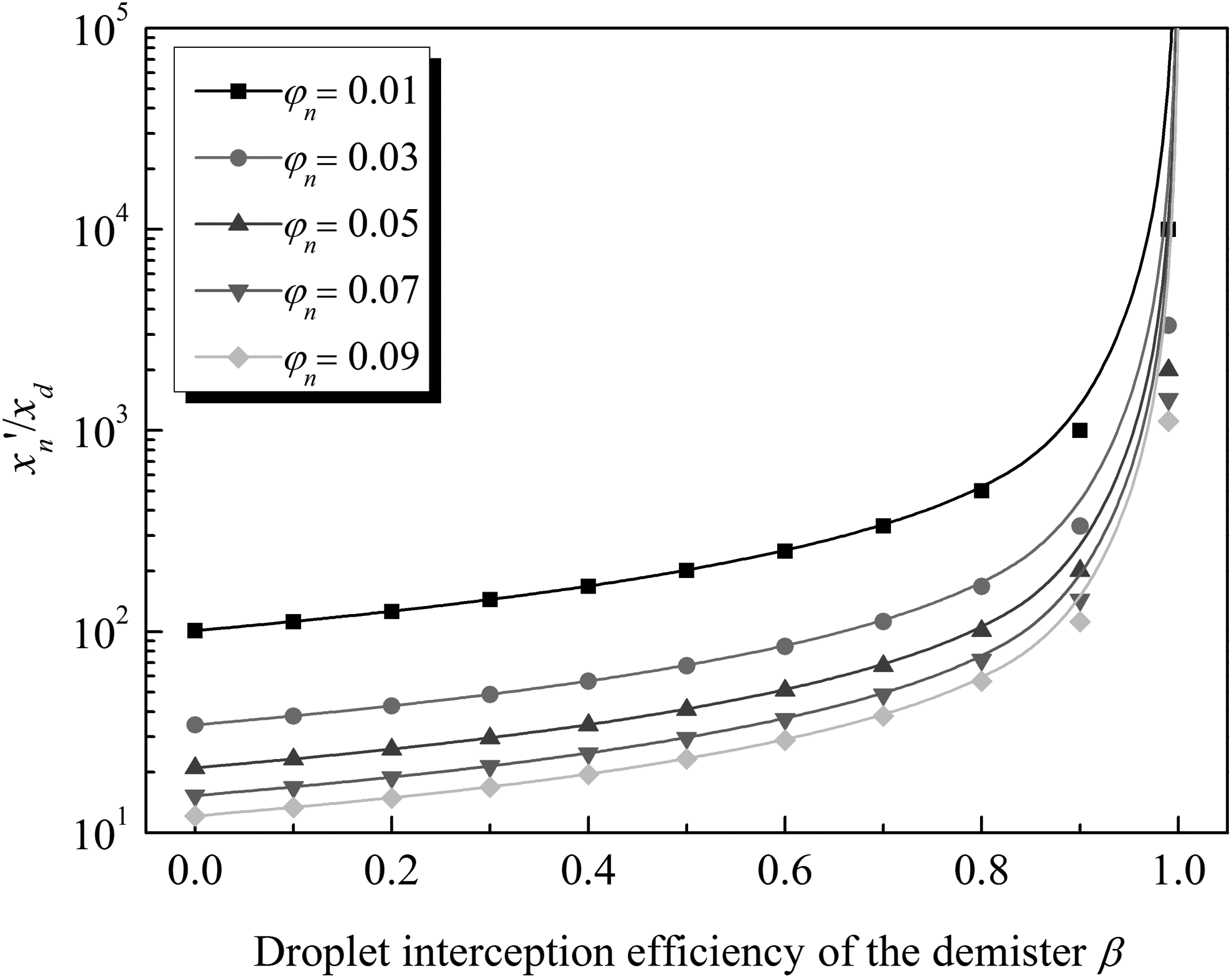
x′n/xd as a function of droplet interception efficiency of the demister under different entrainment rates.
Top sieve tray
The operation on the top tray is somewhat different from other trays. On this tray, the vapor will contact with unsaturated reflux and partial vapor will condense.
(1) Referring to Fig. 2, total mass balance of vapor and solution on the top tray (the nth tray) is stated as follows:
(2) The balance of the solute in top sieve tray gives
Solute concentration in entrained droplets above the nth tray relies on the mixing degree of droplets and reflux distillate on the nth tray.
where xn is solute concentration of reflux distillate on the nth tray, mg/kg.
Rearranging Equations (6), (7), and (8) yields
where Gn−1 is the mass flow rate of vapor rising through the (n−1)th tray, depending on heat transfer between the vapor and distillate, kg/h.
Based on the previous assumption, only a small amount of secondary vapor condenses and releases the latent heat to heat the reflux distillate on the top tray into the saturated state. Energy balance is calculated as follows:
Rewrite Equation (12):
where TR and Ts are the temperature of reflux distillate and saturation temperature of distillate at the operating pressure, °C, respectively; Cp is specific heat capacity of water, kJ/(kg·K); and γ is latent heat of steam condensation, kJ/kg.
The ith sieve tray
For trays below the top tray, vapor does not condensate and the mass flow rate of vapor passing through each tray stays the same, or
(1) For the ith tray (i = n − 1, n − 2, … , 3, 2), total mass balance of vapor and solution is developed as
(2) Solute balance gives
where
Rearranging Equations (15), (16), and (17), the mass flow rate of reflux distillate flowing through the ith tray, Li, solute concentration in entrained droplets above the (i − 1)th tray,
In particular, for the first tray,
where x0 is the solute concentration in the concentrated liquor, mg/kg.
Evaporation chamber
(1) As shown in Fig. 2, in the evaporation chamber unit, the entering masses are feed liquid LB and reflux L1, and the leaving masses include concentrated liquor L0, vapor G0, and entrained droplet e0. Hence, the total mass balance of vapor and solution in this unit is
(2) Mass balance of the solute is
where xB and x0 are solute concentrations, mg/kg, in the feed liquid and concentrated liquor, respectively.
Rearranging Equations (24) and (25) gives
Assume that the entrainment rate and mixing degree factor in the model are known parameters, which will be discussed in the following part. There are totally (3n + 4) independent equations, which are equal to the number of unknowns. Thus, these equations in the model are closed and solvable.
Discussions of Model in Application
Model parameters
Entrainment rate in the decontamination tower is a very significant parameter, which severely determines the DF of the tower. The entrainment in a sieve tray tower relies on many factors, such as tray spacing, gas velocity, and physical properties of gas and liquid (Uys et al., 2012). Hunt et al. (1955) have proposed a simple and practical semiempirical correlation for predicting the entrainment rate in the sieve tray tower.
where us is superficial velocity of vapor, calculated as the volumetric gas flow divided by the perforated area of the tray, m/s; σ is surface tension of the liquid, N/m; and HT and Hf are tray spacing (m) and froth height on the tray (m), respectively.
Besides, the mechanism of entrainment in the evaporation chamber of the tower is different from that of entrainment on the sieve tray. In the evaporation chamber, where feed liquid is heated and evaporated, liquid droplets will be carried by the vapor flowing from the boiling surface, which is called pool entrainment (Sterman, 1958; Lee et al., 1986; Kim and No, 2005). The amount of liquid pool entrainment mainly depends on the vapor velocity and disengaging height. Lee and Lee (1993) proposed a semiempirical correlation for predicting the pool entrainment rate.
where ug is the vapor velocity in the tower, m/s; D is the internal diameter of the tower, m; and HV is the effective height of the vapor space, m.
Droplet interception efficiency of the wire mesh demister (β) mainly relies somewhat on the design of the mesh and gas velocity (Carpenter and Othmer, 1955; Bell and Strauss, 1973; El-Dessouky et al., 2000). According to El-Dessouky's experimental studies, the efficiency of wire mesh demister increases with the increase of gas velocity and the decrease of wire diameter and normally is located between 0.3 and 0.8.
Besides, the mixing degree of entrained droplets and reflux on trays is also an important model parameter, which relies on the gas–liquid flow regime on the sieve trays. Two flow regimes commonly encountered on sieve trays are froth regime and spray regime (Kister et al., 1981; Kister and Haas, 1988). In the froth regime, liquid is continuous phase and gas is distributed as bubbles in the liquid, which mean that contact of gas and liquid is good and mixed on the trays; while in the spray regime, gas is the continuous phase passing through sieve trays so that the contact of gas and liquid is not very inadequate. Obviously, the forth regime on the trays is in favor of adequate contact of the droplets and reflux liquid, thus in this case, α gets close to 1.
Factors affecting the DF
To understand essential factors affecting the DF of the tower and further give theoretical guidance on how to improve the DF, the following simplifications are implemented based on operational characteristics:
Substitute Equations (30)–(32) into Equations (10), (19), and (22),
where r is the reflux ratio, L/G.
The DF is defined as the ratio of solute concentration in the concentrated liquor to that in the distillate.
From the above equations, it can be seen that the DF depends on five factors, entrainment rate (φ), droplet interception efficiency of the demister (β), reflux ratio (r), mixing degree of entrained droplets and reflux (α), and sieve tray number (n).
Assume that vapor–liquid contact on the sieve trays is good, and α is estimated to about 0.8. When β varies from 0 to 0.7 and r is 0.1, the DF of the tower decreases with the increase of φ, as shown in Fig. 4. When φ exceeds 5%, the DF value becomes lower than 103 even for a high demister efficiency (β = 0.7). While φ is lower than 0.1%, the DF can achieve up to 105. Thus, effective gas–liquid separation can decrease the entrainment rate and increase the DF. In engineering, a gas–liquid separation device, such as wire mesh demister, cyclone, or baffle, is recommended.

Relationship between DF and entrainment rate φ. DF, decontamination factor.
Figure 5 relates the DF in logarithmic scale to reflux ratio when n = 3, φ = 0.01, α = 0.8, and β = 0.5. The DF increases with the increase of r. When r is too small, the vapor cannot be fully washed, so the DF is very low. While r exceeds about 10%, the DF growth becomes very small. From an economic perspective, a large amount of reflux distillate is not reasonable since the distillate is our product. Besides, a larger reflux ratio may lead to more energy consumption. Generally, to keep heat loss within reasonable limits, the r selected is about 0.1–0.2.

Relationship between DF and reflux ratio r.
As illustrated in Fig. 6, the mixing degree factor (α) has a strong influence on the DF. The DF increases with the increase of α when n = 3, φ = 0.02, r = 0.1, and β = 0, 0.5. A higher α means more, fully, mixing of droplets and reflux so that the solute concentration in the droplets becomes very low through the mixing and diluting process. If α is larger than 0.7, the DF of the tower with three trays can achieve 103 or more. As previously discussed, the mixing degree depends on the flow regime on the trays. Usually, the froth regime is recommended in the operation of a decontamination tower. In this case, α approaches 1.
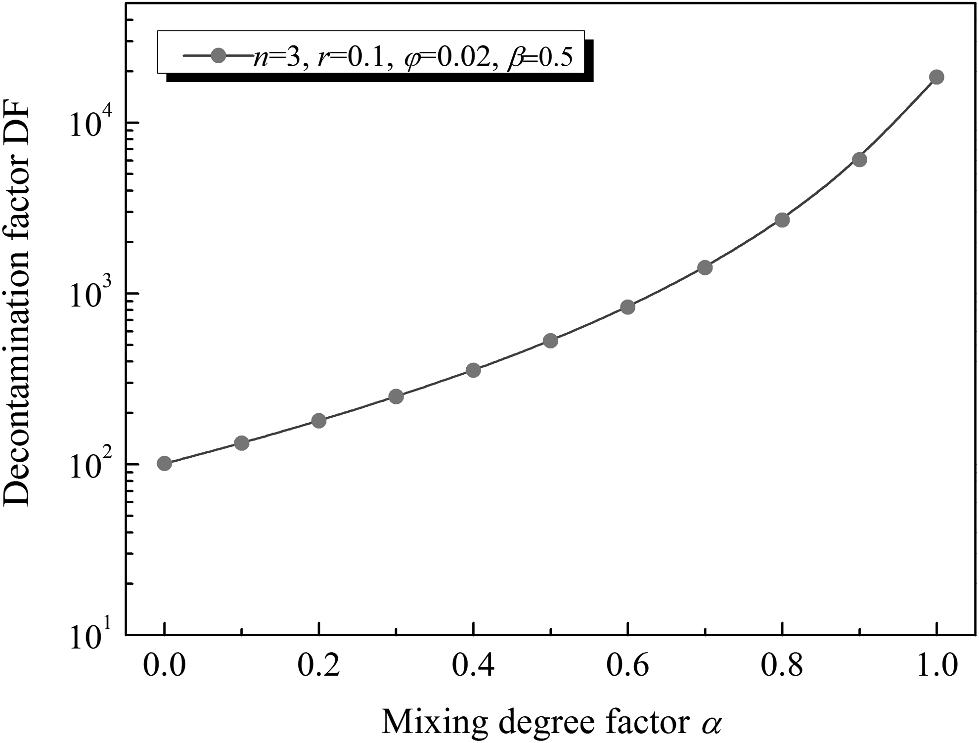
Relationship between DF and mixing degree factor α.
Figure 7 shows that DF increases with the increase of sieve tray number, when α = 0.9, β = 0.5, φ = 0.01–0.05, and r = 0.1. The result shows that only three trays can give DF values in the order of 102–104 for most common operating conditions. This figure gives a theoretical prediction of tray number of a decontamination tower for a design DF value.
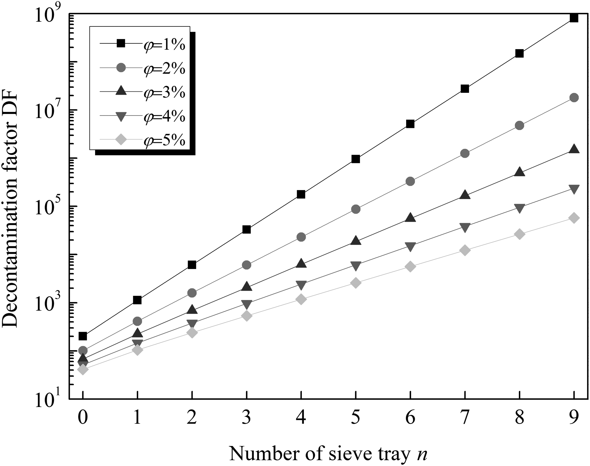
Relationship between DF and number of sieve tray n.
The above quantitative relationships between the DF with various factors are in line with physical facts and our experience, which show the rationality and correctness of this model. Moreover, this model gives us theoretical guidance on how to design a high-efficiency decontamination tower.
Calculation Procedure for Sieve Tray Number
As previously discussed, tray number has a significant influence on the DF of the decontamination tower. Hence, the key to design the decontamination tower is to select a reasonable tray number. Based on this model, a step-by-step procedure is presented for calculating the required tray number corresponding to the desired DF value.
Step 1: Assume that n pieces of sieve trays are required for a desired DF value. Confirm input parameters such as the mass flow rate of the reflux distillate and vapor. The mass flow rates of the vapor passing through different trays are determined by Equations (37) and (14), respectively.
Further confirm model parameters. Calculate the entrainment rate (φ0) in the evaporation chamber and the entrainment rate φi (i = 1, 2, … , n) through the ith tray.
Step 2: Set a design value of solute concentration in the distillate, xd, then calculate the solute concentration in the entrained droplets through the top sieve tray (the nth tray) by Equation (5).
Step 3: Calculate the mass flow rate of the reflux distillate on the nth tray by Equation (9). Then, substitute Equations (5) and (9) into Equation (10) to obtain the solute concentration in the entrained droplets through the (n − 1)th tray.
Substituting Equation (10) into Equation (11) and rearranging, the solute concentration in the reflux distillate on the nth tray is
Step 4: Calculate the mass flow rate of reflux on the ith tray (i = n − 1, n − 2, … , 2), Li, the solute concentration in the entrained droplets through the (i − 1)th tray,
Using the results of the front calculation as input parameters, repeat the iterations until the first tray, and then calculate the solute concentration in the concentrated liquor by Equation (22).
Step 5: Calculate the DF by Equation (36).
If the calculated DF value is larger than and close to the required DF value, then the tray number is reasonable. If the calculated DF value is much larger than the required value, then decrease n, and repeat the calculations starting from Step 2. If the calculated DF value is lower than the required value, then increase n, and repeat the calculations from Step 2.
This design procedure has been programmed in an Excel spreadsheet, thus we can quickly and easily repeat or modify the design calculations.
Application in Engineering Design
A pilot plant was built by the China Nuclear Power Technology Research Institute to simulate the evaporation unit of boron recycle system of the PWR nuclear power plant and test the DF of the decontamination tower as shown in Fig. 8 (Zhen et al., 2015). The evaporation unit mainly consists of a tube heat exchanger, a decontamination tower, a steam condenser, pumps, and so on.
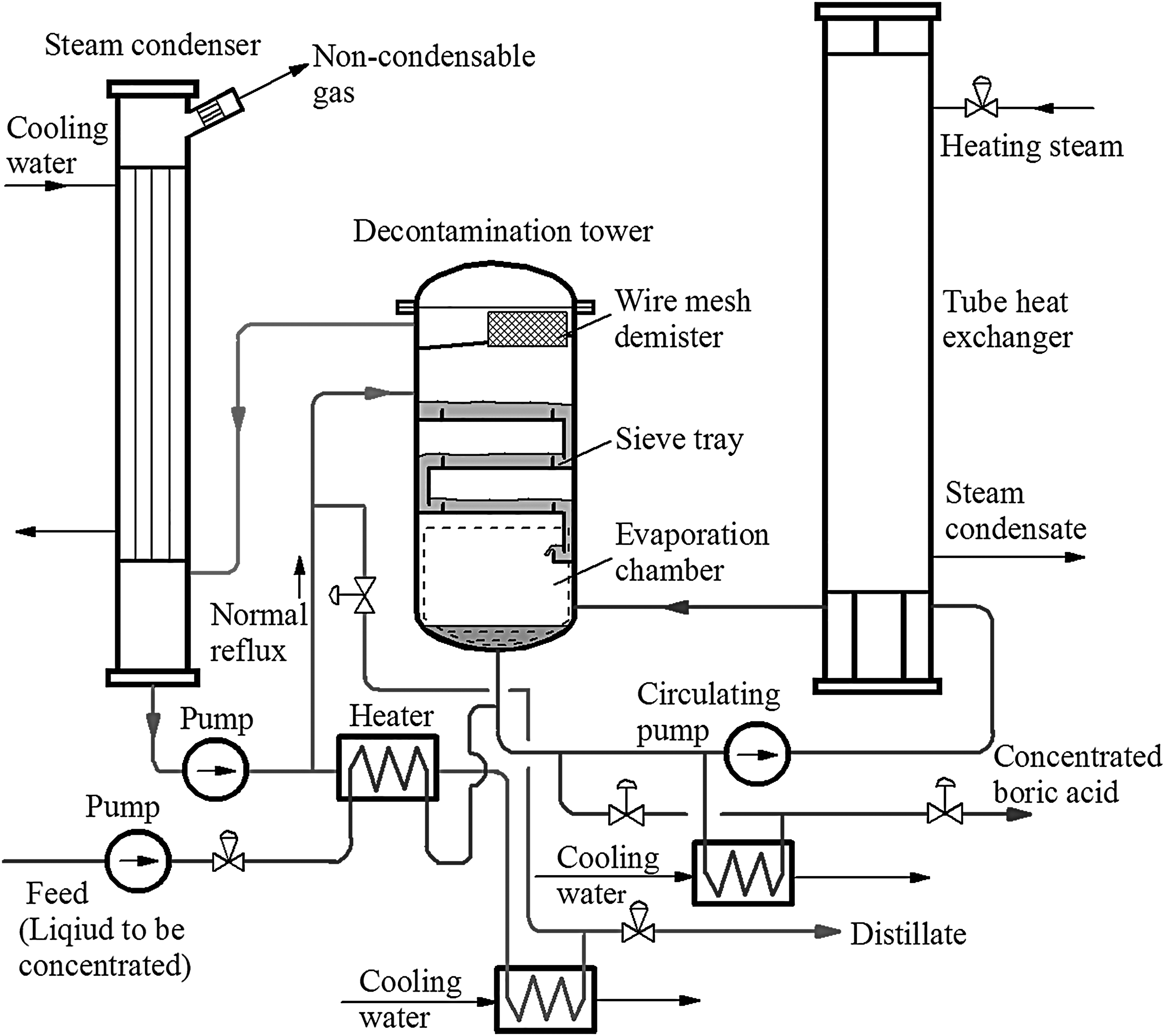
Evaporation process flow diagram of boron recycle system.
The evaporation process is in semicontinuous operation mode. The feed liquid is dilute boric acid solution (∼2,300 ppm), which is heated by the tube heat exchanger and continuously evaporated in the evaporation chamber of the tower. The concentrated liquor remaining at the bottom of the tower is not discharged until boric acid concentration in the concentrated liquor reaches the predetermined value, 7,700 mg/kg. At the end of one period, the boric acid concentration (xd) in the distillate becomes the maximum. The boric acid concentration in the distillate is required to be less than 5 mg/kg. Thus, the designed DF value is at least 1,540. Main structural parameters and operating conditions of the test tower are listed in Tables 1 and 2.
Figure 9 shows the variation of boric acid concentration in the distillate with time under different reflux ratios (r). For the case that r = 0, boric acid concentration in the distillate keeps increasing with time. When boric acid concentration in the concentrated liquor reaches the predetermined value, 7,700 ppm, the boric acid concentration in the distillate is 16.6 ppm, which exceeds the designed value, 5 ppm. For the case that r ≥ 10%, boric acid concentration in the distillate always maintains in very low values (<5 ppm) with time. The test results indicate that the decontamination tower becomes a de-entrainment apparatus and cannot achieve the required DF value if there is no reflux, while only a small amount of reflux can effectively decrease the solute concentration in the distillate. Hence, it once again demonstrates that the function of the decontamination tower is not to remove the entrainment, but to wash and purify the vapor with droplets by using the reflux.
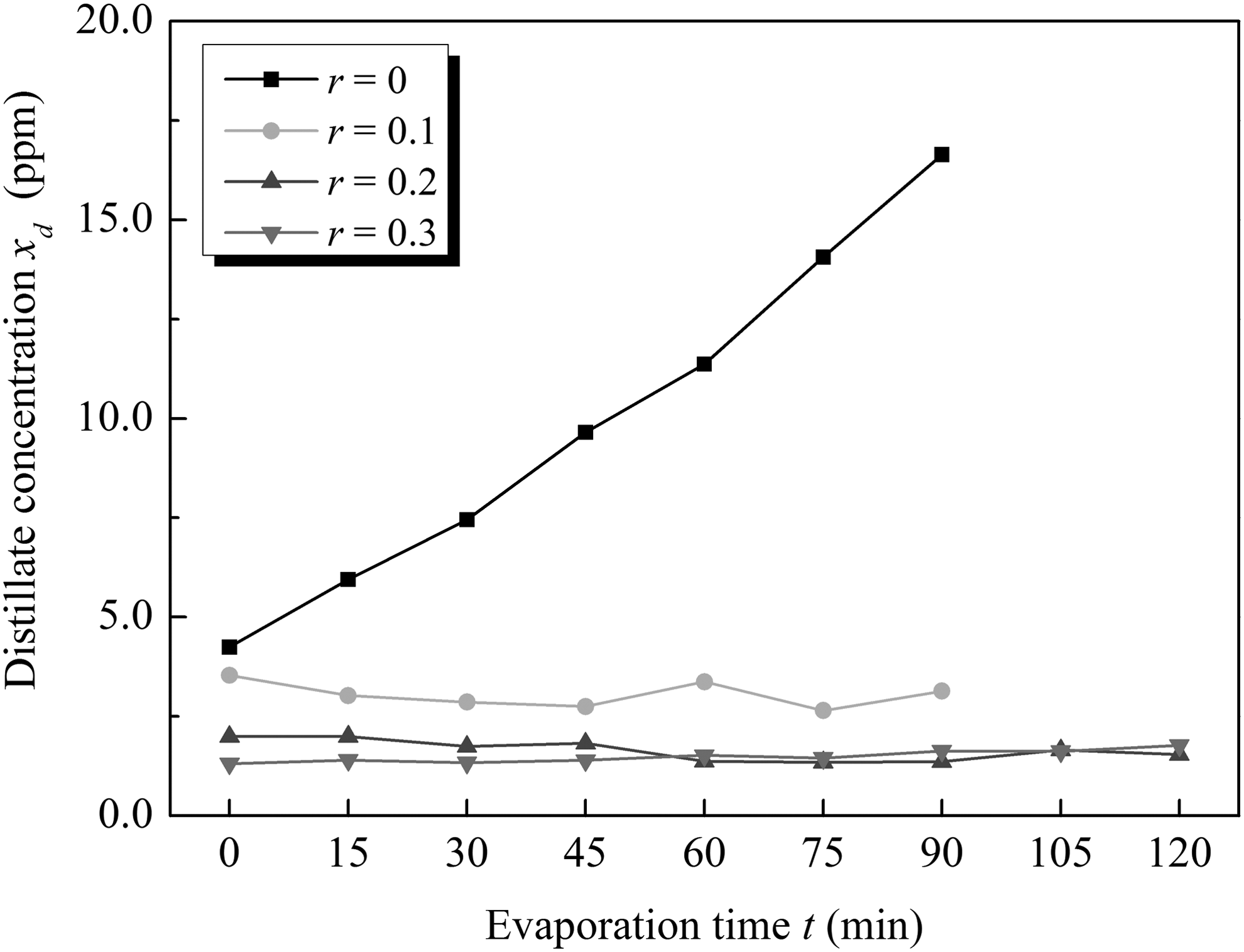
Variation of boric acid concentration in distillate with time.
Figure 10 shows the comparison of the calculated and experimental DF values under different reflux ratios. The calculated DF values agree well with the experimental DF values when the reflux ratio is 10%–30%. The experimental DF value is greater than the calculated value when the reflux ratio is 0. That is due to a lower entrainment rate in the tower when there is no reflux. In this case, the dry sieve tray can be equivalent to a de-entrainment apparatus. However, the DF value under the condition of no reflux is always lower than the ones under the conditions of 10%–30% reflux ratios since the unwashed droplets contain high concentration of boric acid. Both the calculated and experimental DF values increase with the increase of reflux ratio. However, the increase becomes slow when reflux ratio exceeds 10%. This may be related to the gas–liquid flow regime on the tray, which greatly affects the mixing degree of the droplets and reflux.

Experimental and calculated DF values under different reflux ratios.
Figure 11 shows the calculated DF values of the tower with different sieve trays under different reflux ratios by using the proposed model. From the figure, the required DF value (1,540) cannot be achieved no matter how many trays are used if there is no reflux. Two or less trays cannot achieve the required DF value (1,540), but three or more will satisfy the requirement. The calculated results agree with the test results.

Calculated DF values of tower with different sieve tray numbers under different reflux ratios.
Pilot-scale trials have verified that the decontamination tower with three trays can complete the requirement of boron recycle system. Furthermore, based on the similar principle, a plant-scale prototype decontamination tower was designed and built (Li et al., 2015). The main structural and operating parameters of the tower are listed in Tables 3 and 4.
Under the operating condition, calculate a reasonable tray number of the tower for achieving the design DF value (1,540). Figure 12 shows the calculated DF values with different tray numbers. The tower with less than three sieve trays cannot achieve the design value even for a high demister efficiency (β = 0.7), while the DF value of the tower with three trays can reach 2,295 even for a low demister efficiency (β = 0.3). The tower with four trays can give DF values over 5,864 even for a low demister efficiency (β = 0.3), which is far more than the designed value. In view of manufacturing and maintenance costs, three trays are more reasonable. Currently, this tower has been successfully put into use in the Hong Yanhe Nuclear Power Plant in China. Engineering practice has proved that the decontamination tower with three sieve trays can realize the requirement of boron recycle system. Consequently, this model provides a reliable method for the design of the decontamination tower.
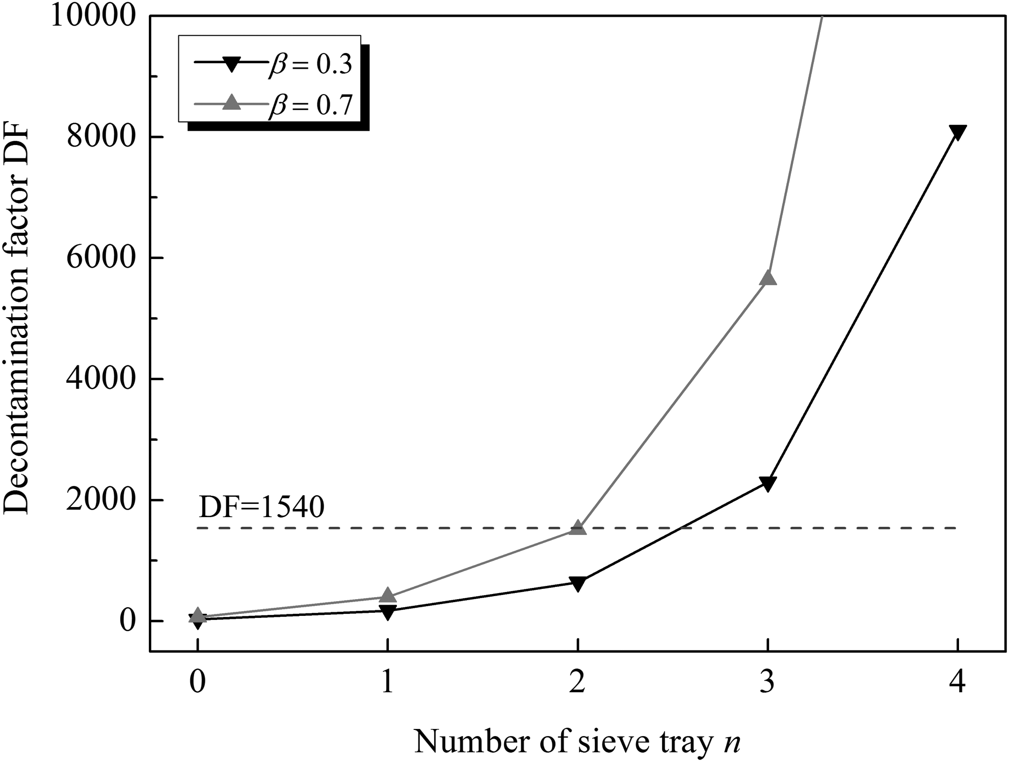
Calculated DF values corresponding to different sieve tray numbers.
Conclusion
For washing of vapor carrying radioactive droplets, the decontamination tower with sieve trays becomes preferred in nuclear power plants because it can achieve high efficiency by using less water and increasing the tray number. The operational features of this kind of tower, when used to wash the secondary vapor carrying radioactive droplets, are analyzed. The mechanism of washing process in the decontamination tower is totally different from the mass transfer process as in a traditional distillation tower. In the washing process of this tower, the droplets entrained by vapor and the reflux distillate are mixed on trays so that the radioactive component of the droplets re-entrained by the vapor becomes diluted and finally decreases to the required concentration. Based on this principle, a mathematical model is developed, which clearly describes the relationship of DF with the sieve tray number, entrainment rate, reflux ratio, and demister efficiency, as well as the mixing degree of the entrained droplets on the trays. According to this model, a step-by-step design procedure is proposed to calculate the required tray number under the designed DF value. Finally, for the TEP system requirement and conditions, a decontamination tower is designed by using the procedure, and the pilot-scale test has verified that the tower can achieve the requirement. Based on the pilot test, a plant-scale prototype tower has been designed and successfully put into use in the Hong Yanhe Nuclear Power Plant in China. The design practice indicates that this model, as a simple but useful tool, can also be applied to the operation analysis and the design of other sieve tray towers operating in similar cases.
Footnotes
Acknowledgment
The authors would like to acknowledge the China Nuclear Power Technology Research Institute for the pilot test data.
Author Disclosure Statement
No competing financial interests exist.