
Abstract
Abstract
A graphene-cobalt/nickel composite-carbon cloth (Gr-Co/Ni-CC) electrode through dip-coating method associated with hydrothermal process-air calcination method was prepared. The scanning electron microscope (SEM), energy dispersive X-ray (EDX), transmission electron microscope (TEM), and X-ray powder diffraction (XRD) techniques proved that the wrinkled graphene sheets and granular Co/Ni composite loaded on the carbon cloth (CC) surface successfully. The highest Brunauer-Emmett-Teller (BET) surface area of the Gr-Co/Ni-CC was obtained (138.821 m2/g), which was effectively higher compared with the CC electrode (1.404 m2/g). Electrochemical measurements revealed that the Gr-Co/Ni composite significantly improved the electrochemical performance of the CC electrode. When Gr-Co/Ni-CC electrode was used as an anode in microbial fuel cell (MFC), compared with the control MFCs, the highest maximum power density (784.89 mW/m2) and the lowest internal resistance (158.52 Ω) were obtained. Furthermore, the MFC with Gr-Co/Ni-CC anode electrode still possessed high treatment ability on organics-rich wastewater. The results declared that the Gr-Co/Ni-CC anode was an effective alternative to boost the MFC performance.
Introduction
A
Graphene can be described as a unique nanostructure composed of sp2-bonded carbon atoms (Allen et al., 2010). Several unique features, including large specific surface area, excellent electrical conductivity, abundant active sites, and high stability distinguish graphene from other carbon-based materials (ELMekawy et al., 2017; Shaari and Kamarudin, 2017). Those superior properties of graphene-based electrodes have attracted extensive research on anode materials for MFCs (Chou et al., 2014; Zhang et al., 2016; Ong et al., 2017). Generally, graphene can be divided into graphene sheet and functionalized graphene. Functionalized graphene refers to the graphene that is functionalized through doping with negatively charged atoms (e.g., nitrogen and sulfur) or modifying functional compounds and metallic elements (Ci et al., 2015; ElMekawy et al., 2017). For instance, Zou et al. (2015) prepared nanocrystalline TiO2/reduced graphene oxide (TiO2/rGO) composite electrode and used as an MFC anode. The results showed that the good hydrophilicity and biocompatibility of TiO2, as well as the excellent electrical conductivity of rGO distinctly improved the catalytic activity of the anode. Chou et al. (2014) produced an rGO/carbon nanotube electrode by dip-coating method. The MFC system equipped with the modified electrode exhibited the maximum power density of 335 A/m3, revealing higher durability and extraordinary electrochemical capability than conventional carbon-based electrodes. Overall, numerous studies have proved that functionalized graphene anodes can improve MFC performance by increasing electron transfer efficiency and more active microbial-electrode-electrolyte interactions (Yuan and He, 2015).
In recent years, graphene-precious metal catalysts have received great care and caution, due to their outstanding properties, including high physical and chemical stability, abundant active sites, and strong electron transfer capability. (Yan et al., 2013; Sun et al., 2014). However, serious disadvantages of precious metals are high costs, limited availability, catalyst poisoning, and environmentally detrimental production process, which impede their practical application (Kannan and Gnana Kumar, 2016). Hence, great efforts have been devoted to developing inexpensive graphene-nonprecious mental catalysts, among which transition metals have received increasing research interests because of their strong redox performance and modification flexibility as electrode catalysts. (Hou et al., 2016; Zhang et al., 2016).
Nevertheless, studies on the performance of graphene-transition metal as MFC anode catalysts are still in the early stages. This research on graphene-based electrodes almost focused on how to enhance the electricity production of MFCs (Table 1). The performance of electricity production is raised, because the premise is that high pollutant removal efficiency is more significant for the application of MFC's in wastewater treatment filed (He et al., 2016, Pandey et al., 2016). Therefore, the main purpose of this article is to discuss the feasibility of graphene-transition metal composite as anode catalysts for sustainable wastewater treatment with bioenergy recovery of MFC systems. The dip-coating method is direct deposition by dipping graphene suspension on the surface of the electrode. This method has been widely applied to prepare the Gr-based electrodes because it simplifies the electrode fabrication process (Chou et al., 2014; Ong et al., 2017). The hydrothermal method was often employed to prepare non-noble metal catalysts, owing to its advantages of high particle purity, good crystal shape available to control, and low production cost (Wang et al., 2013a; Mehdinia et al., 2014). So, dip-coating and hydrothermal process-air calcination methods were used as reliable and efficient procedures to fabricate a graphene-cobalt/nickel composite-carbon cloth (Gr-Co/Ni-CC) electrode in this work. Graphene-carbon cloth (Gr-CC), cobalt/nickel composite-carbon cloth (Co/Ni-CC), and bare carbon cloth (CC) electrodes were produced as control electrodes. The morphologies and electrochemical properties of the four electrodes were characterized. Furthermore, performances of MFCs with the Gr-Co/Ni catalyst-modified CC anode were explored, aimed to provide an alternative anode material for the application of the functionalized graphene in MFCs.
CC/Pt, carbon cloth/platinum; CF, carbon felt; COD, chemical oxygen demand; CP, carbon paper; CVD, chemical vapor deposition; GF, graphite felt; GNs, graphene microsheets; GO, graphene oxide; GP, graphite plates; Gr, graphene; GZMA, graphene oxide-zeolite composite; MFC, microbial fuel cell; NGNS, N-doped graphene nanosheets; PANI, polyaniline; PPy, polypyrrole; rGO, reduced graphene oxide; SS, stainless steel.
Experimental Protocols
Chemicals and materials
Single-layer graphene was purchased from Aimi Graphene Investment Management Co., Ltd. (the carbon content is more than 95.0%, the oxygen content is less than 2.50%, and the specific surface area is 400–600 m2/g). Nafion solution (5%, DuPont D520), CC (HCP331N), and proton exchange membrane (PEM, Nafion117) were produced by Shanghai He-sen Electric Co., Ltd. All chemicals were of analytical reagent grade. De-ionized water was used for all experiments.
Fabrication of electrodes
Before use, the bare CC (5 × 6 cm) was cleaned in 10% HCL and acetone for 6 h and 3 h, respectively, then sonicated for 1 h, washed with deionized water to neutralize and dried at 50°C for 12 h (Mehdinia et al., 2014). Then, the Gr-CC was prepared using the dip-coating method and Co/Ni-CC electrode was prepared using the hydrothermal process-air calcination method. Finally, the two methods were combined to prepare the Gr-Co/Ni-CC electrode.
The specific fabricated steps were according to the schematic diagram (Fig. 1), which were described as follows: for the preparation of Gr-CC, 10 mg graphene powder and 1 mL deionized water were mixed with ultrasonic treatment for 1 h to obtain Gr dispersion (10 mg/L), then 1.2 mL Nafion solution was added into the mixture, followed by ultrasonication for 20 min, which was named reagent 1. Gr-CC was prepared by dipping reagent 1 on the surface of pretreated CC and then dried naturally. Next, the fabrication of Co/Ni-CC included four steps: (1) dissolving 1 mmol/L NiNO3·6H2O, 2 mmol/L CoNO3, 6 mmol/L NH4F, and 15 mmol/L urea into 40 mL deionized water, which was named reagent 2, (2) immersing pretreated CC into reagent 2 for 30 min and then transferring to an oven at 105°C for 10 h, (3) after the reaction was completed, the sample was washed alternately with alcohol and de-ionized water to remove the loosely bound residue on the CC surface, and (4) finally, the sample was calcined in air at 250°C for 6 h. As for the preparation of Gr-Co/Ni-CC, first, the Co/Ni-CC was prepared according to the steps mentioned above, and then the following procedures were the same as the Gr-CC.

Schematic diagram for the fabrication process of prepared electrodes. CC, carbon cloth; Co/Ni-CC, cobalt/nickel composite-carbon cloth; Gr-Co/Ni-CC, graphene-cobalt/nickel composite-carbon cloth.
Prepared electrodes characterization
The surface morphologies and elemental analysis of the prepared electrode were analyzed, using an SEM with coupled energy dispersive spectroscopy (SEM-EDS; JSM-7500F, Japan) and a TEM (ZEISS Libra 200 FE) with an accelerating voltage of 200kV. The XRD patterns of Gr-Co/Ni composite was identified through a powder diffractometer using CuKα radiation at a scanning speed of 2°/min (PANalytical B.V., Holland). The specific surface areas of the prepared electrodes were detected by nitrogen adsorption based on BET method using a surface area analyzer (ASAP2020). After applying prepared electrodes to MFC systems, the biocompatibility of the Gr-Co/Ni-CC and control electrodes was examined by SEM. The procedures of sample preparation were as follows: first, the samples (cut from anodes) were immersed in 2.5% glutaraldehyde solution for more than 2 h to stabilize the bacteria fixed on the anodes. Following rinsing with a phosphate-buffered saline (PBS) solution (pH = 7.0) thrice, each time for 15 min, the samples were dehydrated in ethanol series (30%, 50%, 70%, 80%, 90%, and 100%, each for 10 min), and further dipped in isoamyl acetate for 15 min. At last, the samples were air-dried for further use.
The electrochemical analyses, including cyclic voltammetry (CV) and impedance spectroscopy (EIS) of the prepared electrodes, were acquired using a CHI660E system (Shanghai, Chen-hua Instrument Co. Ltd) with a conventional three-electrode cell. The prepared electrodes, the platinum plate electrode, and the saturated calomel electrode were used as the working electrode, the auxiliary electrode, and the reference electrode, respectively. The CV was displayed by sweeping applied voltage ranging from −1 to 1 V at a scan rate of 0.05 V/s. EIS was executed under open-circuit voltage of the frequency shifting from 0.1 Hz to 100 kHz. Both the CV and EIS were tested in 0.1 mol/L PBS solution (10.7 g/L K2HPO4 and 5.3 g/L KH2PO4, pH = 6.9) (Hou et al., 2013).
MFC setup and operation
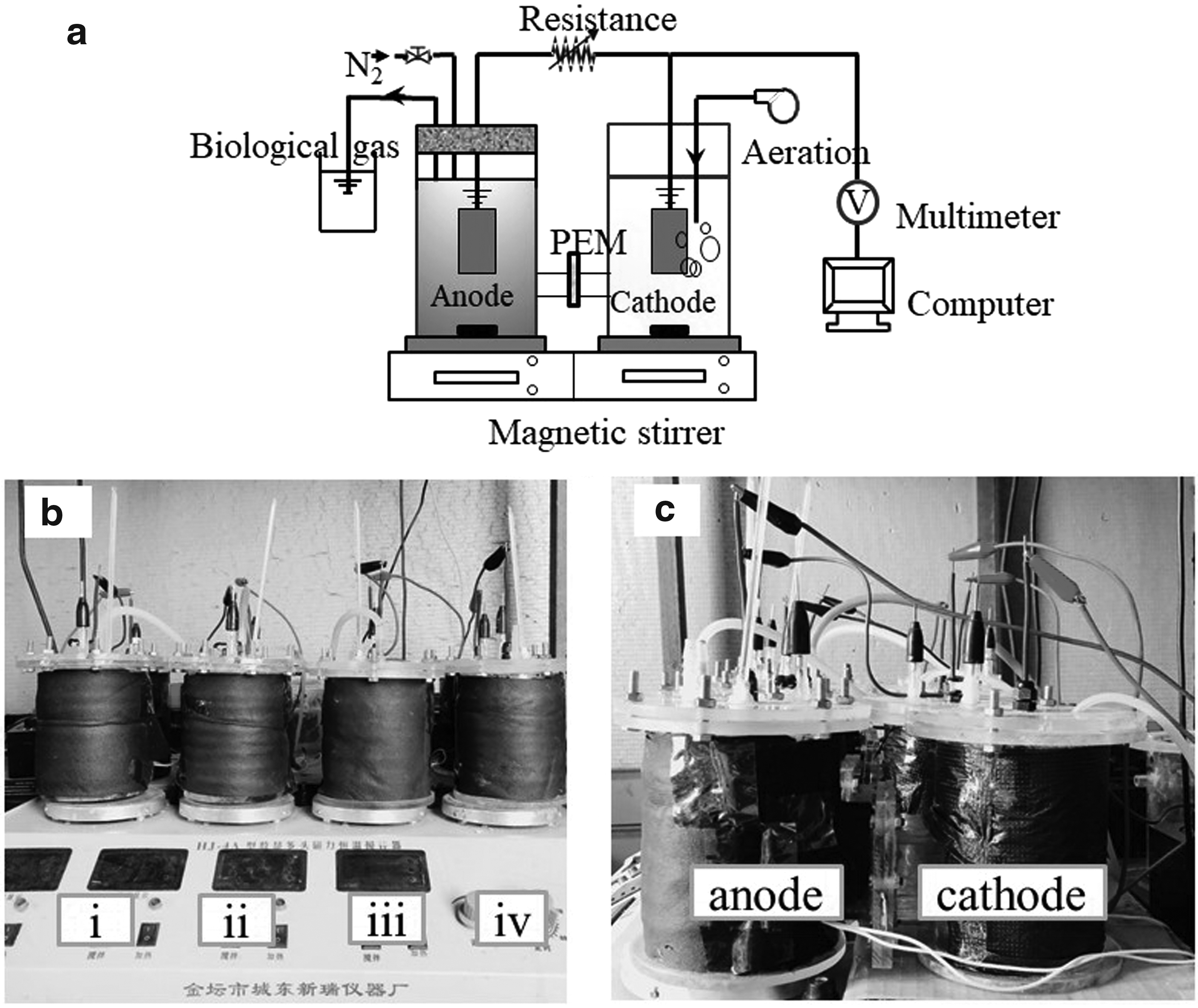
Four identical dual-chamber MFCs (with a liquid volume of 700 mL each chamber) made of plexiglas material were fabricated (Fig. 2). The two chambers of each MFC system were separated by a PEM of size 2 × 2 cm (Fig. 1). The modified electrode (Gr-Co/Ni-CC) and control electrodes (Gr-CC, Co/Ni-CC and CC) functioned as the anodes (5 × 5 cm) for each MFC system, while carbon papers (5 × 5 cm) were used as cathodes for all MFCs. The anode chambers were inoculated with a mixed bacterial culture collected from the anode anaerobic sludge of the glucose-fed AFB-MFC. This AFB-MFC reactor has been operated in our laboratory for more than 1 year (Liu et al., 2017). The anolyte was composed of 3.50–5.00 g/L C6H12O6, 0.47–0.68 g/L NH4Cl, 0.11–0.16 g/L KH2PO4, and 1 mL trace metal stock solution (containing EDTA, H3BO3, ZnSO4·7H2O, CoSO4·7H2O, CuCl2·2H2O, MnSO4·H2O, NiSO4·6H2O, FeSO4·7H2O, and (NH4)2MoO4) (Liu et al., 2017). The cathode chambers were fed with potassium ferricyanide solution containing PBS solution (0.1 mol/L, pH = 7.0). The anode chambers were slowly mixed using magnetic stirrers to minimize mass transfer limitations. The cathode chambers were equipped with an aerator to control dissolved oxygen (DO) at 7–8 mg/L. All MFCs were operated in batch mode with an external resistor of 1,000 Ω under ambient temperature adjusted to 30°C ± 3°C. The anolyte and catholyte were simultaneously changed when the output voltage dropped obviously. Nitrogen was inlet into the anode chamber for 15 min to remove DO from the anolyte after replenishing with the fresh substrate each period.
Evaluation of MFC performance
The generated voltage was measured every 180 s by a professional electronic multimeter (UT70B; Uni-Trend Group Ltd) and recorded with a computer. When the voltage output approached the steady state, polarization curve method was used to measure the voltage of MFC under different external resistance conditions. The polarization and power density curves were obtained from Equations (1) to (2).
where jA is area density (mA/m2), I is current (mA), V is voltage (mV), Rex is external resistance (ranging from 10 to 5,000 Ω), and A is anode area (25 cm2).
The chemical oxygen demand (COD) of anolyte was gradually increased from 3,500 to 5,000 mg/L and was determined by standard method (Walter, 2005). The removal of COD was tested on day 1 (with stable voltage output) and day 2 (with dramatically dropped voltage output).
Results and Discussion
Surface characterization of prepared electrodes
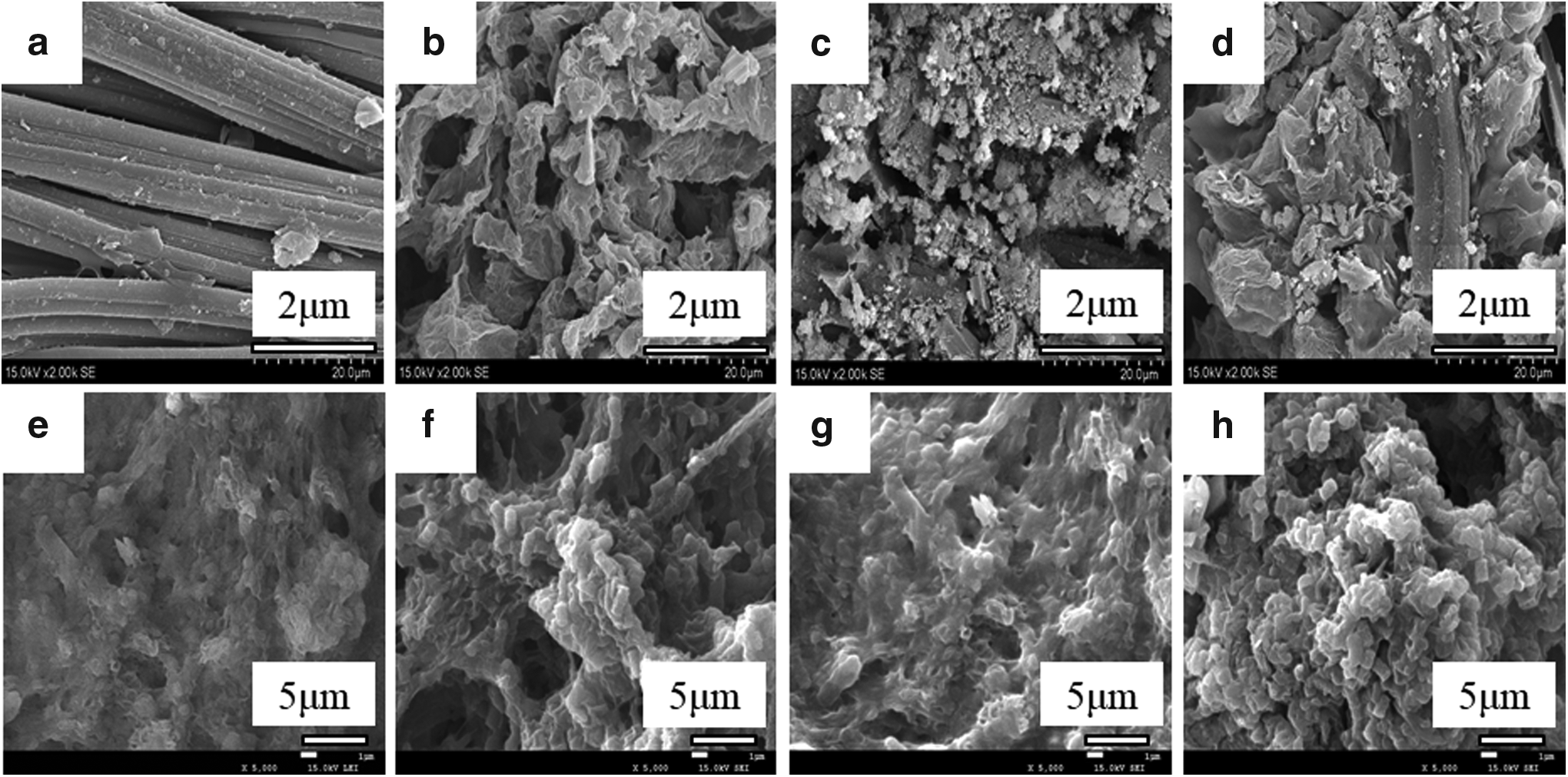
The morphologies of the CC, Gr-CC, Co/Ni-CC, and Gr-Co/Ni-CC electrodes were visually examined by SEM. Compared with the smooth carbon fiber of the CC (Fig. 3a), the thin wrinkled and crumpled structures of the Gr-CC (Fig. 3b) ensured the loading of graphene sheets, agreeing well with the previous results (Zou et al., 2015; Yang et al., 2016). Figure 3c showed that a large amount of small granular substances was randomly aggregated on the surface of CC, presumably that Co/Ni was deposited certainly. For the SEM image of Gr-Co/Ni-CC (Fig. 3d), both the thin wrinkled and crumpled graphene sheets and small granular substances were observed on CC surface. The obtained TEM images also showed that the Gr (Fig. 4a) displayed a typical crumpled structure and comprised several layers of graphene. As for the Gr-Co/Ni composite (Fig. 4b), it can be found that large amounts of small sized Co/Ni composite were randomly deposited on the surface of the stacked graphene sheets. The TEM image of the Co/Ni composite presented in the inset of Fig. 4b revealed its crystalline nature. To further confirm the successful loading of Co/Ni composite, EDX analysis of Co/Ni-CC and Gr-Co/Ni-CC was conducted. The results (Fig. 5) revealed that the contents of Co and Ni in Co/Ni-CC were 29.66% and 21.35%, while the contents of Co and Ni in Gr-Co/Ni-CC were 22.38% and 14.13%. These results proved that Co/Ni loaded on CC surface successfully.

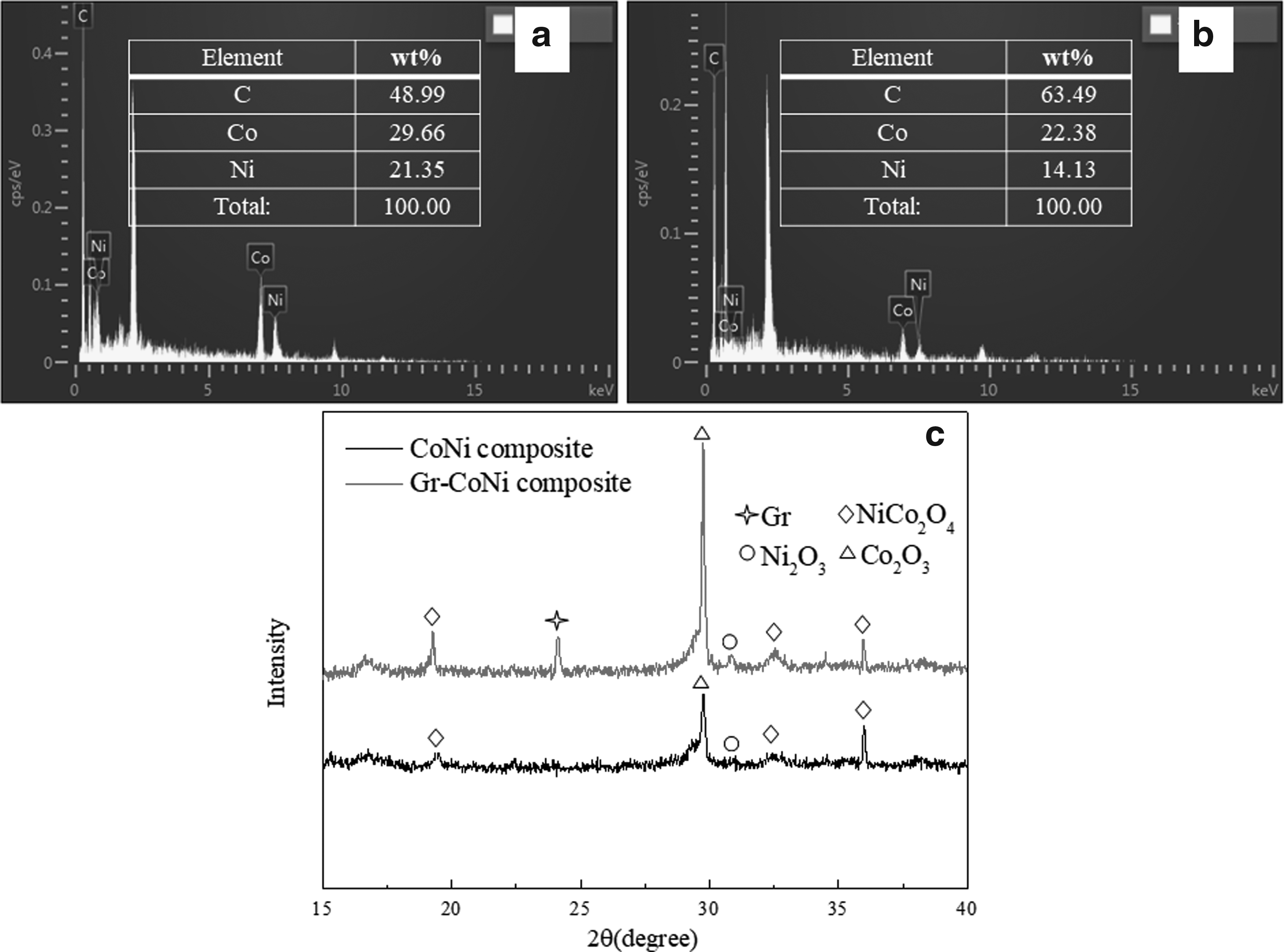
The crystal structure of Gr-Co/Ni and Co/Ni composites was examined and compared by XRD (Fig. 5c). For the Co/Ni sample, the feature peaks at 19.28°, 32.58°, and 35.96° are corresponding to the NiCo2O3, demonstrating the successful synthesis of the Co/Ni composite. Moreover, the peak at 28.76° and 30.88° represent Co2O3 and Ni2O3, respectively, which were generated as by-products during the Co/Ni composite synthesis process. As for the Gr-Co/Ni sample, a diffraction peak of Gr appeared at around 24.5°, indicating the addition of graphene (He et al., 2013a; Zou et al., 2015). The BET surface area of the Gr-Co/Ni-CC was 138.821 m2/g, which was significantly higher compared with the CC electrode (1.405 m2/g). The highest surface area of Gr-Co/Ni-CC suggested that the loading of Gr-Co/Ni composite reduced mass transfer resistance and in turn enhanced electron transport (Karra et al., 2013). It is worth noting that the specific surface area of Gr-CC is 80.980 m2/g, which is smaller than no binder-treated graphene (the specific surface area of the unprocessed graphene is around 400–600 m2/g). It might be attributed to the use of a binder (Nafion), which is the graphene nanosheets may overlap with each other or be coated with the insulating binder, so that the large specific surface area and high electrical conductivity of the graphene could not be fully exhibited (Wang et al., 2013b). However, the specific surface area of CC has been significantly improved by modifying with Gr-Co/Ni composite. Predictably, the large surface area and high conductivity of graphene associated with abundant active sites and high catalytic activity of Co/Ni (Hou et al., 2016) are beneficial to achieve superior bioelectrochemical performance.
To evaluate the biocompatibility of the Gr-Co/Ni-CC, the surface morphologies of the Gr-Co/Ni-CC and control anodes were examined immediately after MFC systems running for a couple of days (54 days). As depicted in Fig. 3e–h, it can be found that abundant bacteria adhered to all the anodes' surfaces to form a bioactive layer. This result is an indicative of the conclusion that the prepared electrodes all have excellent conductivity and biocompatibility, which contribute to the adhesion of high-density bacteria. In other words, the combined modification of graphene and Co/Ni has no obvious effect on the biocompatibility of the CC anode. This phenomenon may be explained for two reasons. On the one hand, modification with graphene increased the surface area, conductivity, and then accelerated electron transfer efficiency (Liu et al., 2012), while deposition of Co/Ni supplied abundant active sites and high catalytic activity (Hou et al., 2016). The synergistic effects of graphene and Co/Ni were conducive to biofilm formation. On the other hand, the antibacterial activity of Gr-Co/Ni may have an adverse impact on the adhesion of microorganisms (Chen et al., 2015; Kannan and Gnana Kumar, 2016) (this section has been further discussed in Electrochemical Performance of MFC section). In a summary, perhaps the mentioned two opposite effects on the biocompatibility of Gr-Co/Ni-CC anode resulted in no obvious influence between Gr-Co/Ni-CC and CC anodes.
Electrochemical behaviors of prepared electrodes
CV tests were conducted in 0.1 mol/L PBS to evaluate the electrochemical activities of our as-prepared anodes, and CV curves are shown in Fig. 6a. It can be seen from Fig. 6a, the Gr-Co/Ni-CC electrode possessed the largest area of the close curve and the peak electrochemical response current, followed by Gr-CC, Co/Ni-CC and CC. The large size of the closed curve is related to the superior capacitance, the amount of charge transfer during the redox process, and the better conductivity of the electrode materials (Zhang et al., 2016). Moreover, Tang et al. (2015) proved that the maximum power density was positively correlated with the areal capacitance of the bioanodes in the MFCs. It can be explained that the anodes integrated with internal capacitors enhance the performance of MFCs due to the improved transient charge storage behavior of the anodes (Deeke et al., 2012; Peng et al., 2012). Therefore, the largest response current and closed curve size of Gr-Co/Ni-CC illustrated that the modification of Gr-Co/Ni increased the electrochemical capacitive of the CC, thus indicating the possibility of high power density in MFCs.

The EIS technique is a common method to calculate the resistance, the charge transfer and ion mobility properties of electrodes, thus indicating the interfacial properties between electrolyte and electrode (Kumar et al., 2014a). Nyquist plot is the most widely used graphical expression in EIS; it can clearly reflect the values of the two different parts of the electrode resistance, including the ohmic resistance (Rohm) and the charge transfer resistance (Rct). Specifically, the Rohm is determined by the high frequency intercept with the x-axis, while the diameter of a semicircle in the middle and low frequency range represents the Rct (He and Mansfeld, 2008; Khilari et al., 2013). In this article, ZSimDemo 3.30d was used for the fitting of Nyquist plots data to get the values of Rohm and Rct. Fig. 6b showed the impedance spectra (Nyquist plots) of the prepared four electrodes at their open circuit voltage in 0.1 mol/L PBS solution. The Rohm values of CC, Gr-CC, Co/Ni-CC, and Gr-Co/Ni-CC electrodes were calculated to be 8.17, 7.63, 6.82, and 3.59 Ω, respectively. Compared with Co/Ni-CC, Gr-CC, and CC, the Rohm of Gr-Co/Ni-CC decreased by 1.90, 2.13, and 2.28 times, revealing that the intrinsic resistance of Gr-Co/Ni was lower compared with common carbon-based materials (Lv et al., 2013). The Rct values of CC, Gr-CC, Co/Ni-CC, and Gr-Co/Ni-CC electrodes were calculated to be 57.25, 36.27, 28.11, and 8.7 Ω, respectively. The Rct value was directly correlated to the interfacial interaction between the electrode and the reactant/electrolyte, and the lower Rct value means high electron transfer efficiency (Cao et al., 2016; Chen et al., 2017). Hence, the smallest Rct indicated that the electron transfer efficiency of Gr-Co/Ni-CC was significantly enhanced than control electrodes. This excellent performance can be owing to the large specific surface area, abundant active sites, and excellent conductivity of Gr-Co/Ni. As a conclusion, the modification of Gr-Co/Ni could be beneficial to the interaction between the bacterial cells and the electrodes, which declines mass and electron transfer resistances (Kumar et al., 2014b).
MFC performance
Electrochemical performance of MFC
Four MFC systems with CC, Gr-CC, Co/Ni-CC, and Gr-Co/Ni-CC anodes each were operated 54d under fed-batch mode. The performances of different MFCs were examined, analyzed, and compared at an external resistance of 1,000 Ω. The generated voltages of different MFCs were shown in Fig. 7. In general, apart from the voltages not being stable in the first 2 periods, upon replenishing with the fresh substrate from the third cycle, the output voltage increased rapidly to the maximum value, and then gradually decreased after a time of stability. This trend of voltage change was consistent with other similar studies (Hou et al., 2013; Lv et al., 2013; Huang et al., 2016). Due to the influence of anode materials, the produced voltages of four MFCs displayed differently. As expected, the highest voltage of 714 mV was obtained of the MFC equipped with the Gr-Co/Ni-CC anode, which raised 1.72, 1.08, 1.11 times of MFCs with CC, Gr-CC, and Co/Ni-CC anodes, respectively. Moreover, compared with the control MFCs, the voltage output of Gr-Co/Ni-CC anode was more persistent, especially in the last two periods of the operation. These results indicated that the Gr-Co/Ni-CC anode can significantly boost the bioelectricity generation, as the result of the large specific surface area for bacterial adhesion and abundant active sites for charge transfer of Gr-Co/Ni-CC.
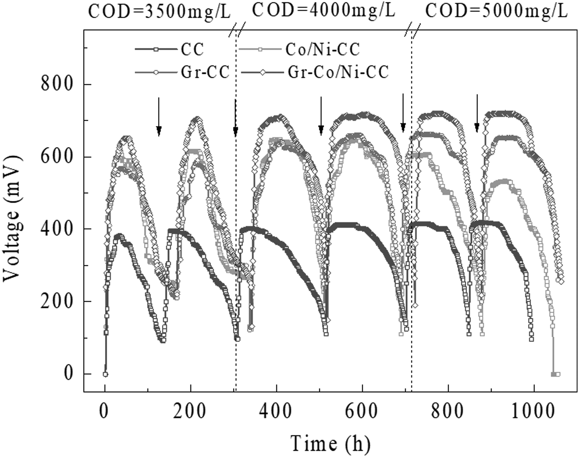
Output voltage of MFCs with different anodes (electricity production by the four MFCs at an external resistance of 1,000 Ω. The arrows indicate the time point when the anolyte was replaced).
When the produced voltages of Gr-CC-MFC and Co/Ni-CC-MFC were compared, it can be seen from that the harvested voltage of Gr-CC-MFC was lower than Co/Ni-CC-MFC in the first two periods, and then gradually exceeded the Co/Ni-CC-MFC. This phenomenon presumably ascribed to the antibacterial effect of graphene. That is, during the initial growth phase of biofilms on the Gr-CC surface, the internal bacteria played a major role in extracellular electron transfer process and were prone to be affected by the antibacterial activity of graphene, owing to the direct contact with graphene, thus resulting in declined electrochemical activity (Das et al., 2013). However, as the formation of a biofilm matrix on the anode surface, there was a large amount of exoelectrogenic bacteria that embedded in extracellular polymeric substances (EPS), which could protect the internal biofilm bacteria from the antibacterial effect of graphene (Kang et al., 2012). Furthermore, once the mature biofilm formed, the biofilm bacteria have been able to promote long-range electron transfer through conductive filamentous appendages (bacterial nanowires) or EPS. In other words, the biofilm bacteria could cross the multilayer biofilm to transfer electrons, increasing its capacity to produce electricity (Hu et al., 2010; Chen et al., 2015). It is noteworthy that the ability of Gr-CC-MFC to harvest electricity still outperforms CC-MFC, suggesting that the antibacterial properties of graphene did not have an evident impact on the electricity production of MFC. Besides, we found that the generated voltages of Co/Ni-CC-MFC declined apparently in the last two periods of the operation. It may be incurred by the shedding of Co/Ni, which should have loaded on the CC surface, leading to the decrease in electron conductivity. Moreover, previous studies also pointed out that transition metal particles and their oxides were highly unstable and expressed low mechanical strength in aqueous environment (Kannan and Gnana Kumar, 2016). Cheng and Logan (2007) also stated that electrodes made of metals were not friendly for bacteria to attach and thus lowered the electricity generation of the MFC. Hence, the inhibitory effect of the exfoliated Co/Ni to microorganisms is another crucial reason for the voltage output drop of the MFC with Co/Ni-CC anode.
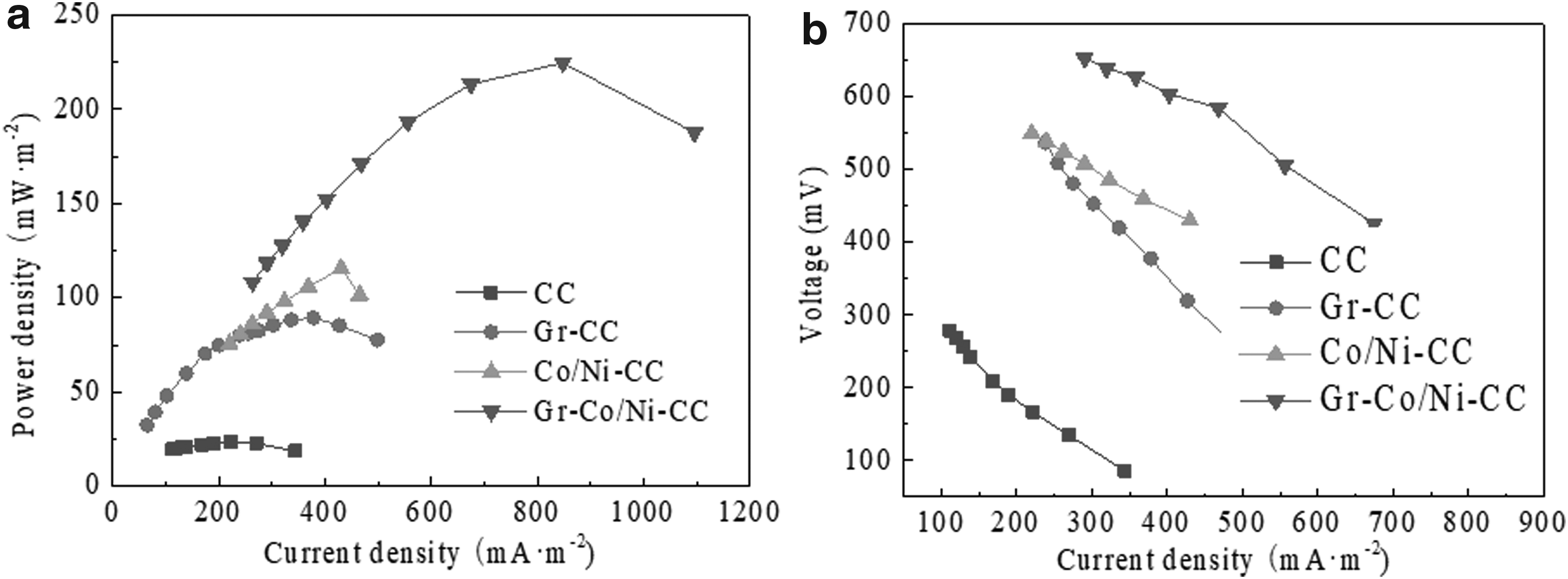
To assess the electrocatalytic activity of Gr-Co/Ni-CC toward MFC performance, the power density and polarization curves of four MFC systems were obtained by using various external loading resistances (10–5,000 Ω). As depicted in Fig. 8, the MFC with Gr-Co/Ni-CC anode yielded the highest maximum power density of 784.89 mW/m2, which improved about 1.16, 1.03, and 1.94 times of Gr-CC (679.46 mW/m2), Co/Ni-CC (767.67 mW/m2), and CC (405.46 mW/m2), respectively. The internal resistance of the MFC with Gr-Co/Ni-CC anode was 158.52 Ω, which decreased 2.73, 1.49, and 2.90 times of Gr-CC (432.9 Ω), Co/Ni-CC (236.44 Ω), and CC (459.31 Ω), respectively. From the above results, the highest maximum power density and the lowest internal resistance confirmed the synergistic effects of graphene and Co/Ni, namely, the unique graphene structure can provide large amounts of active sites for the Co/Ni composite, making the Gr-Co/Ni catalyst possess excellent redox activity and stability simultaneously. Therefore, this combined modification can obtain large active area and strengthen the electron transfer between microorganisms and electrode, which is conducive to the formation of biofilm, thus improving the power output and reducing the internal resistance. Similar results were obtained with a Co3O4/three-dimensional (3D) graphene anode prepared by Prasad et al. (2014). The graphene provided a 3D scaffold to support enough Co3O4 particles that formed a high conductivity 3D network and porous structure. This structure was beneficial to accelerate charge transfer and diffusion of mass.
Wastewater treatment efficiency of MFC
During the operation, the pollutant (COD) removal efficiency of MFCs with different anodes was investigated. The amount of remaining substrate in anolyte on day 1 (with stable voltage output) and day 2 (with dramatically dropped voltage output) was measured. Figure 9 showed the COD removal efficiency of four MFCs with different anodes in six periods, suggesting that all MFCs displayed a similar tendency of COD removal and resulted in high treatment efficiency for organics-rich wastewater. Moreover, from the beginning of the operation until the voltage reached its maximum as well as the steady period, the substrates consumed rapidly and 75% ± 10% of organics were removed. It can be explained when the fresh substrates were supplied, fuels available to the electro-microorganisms were sufficient, and then enhanced the microbial activities resulting in an increased voltage. As the substrates depleted, the fuels available for electro-microorganisms reduced and the voltages decreased gradually (Zhuang et al., 2012; He et al., 2013b; Moqsud et al., 2013). In addition, it was a remarkable fact that the loading of Gr-Co/Ni on the CC surface expressed no evident effect on the removal rate of organics. This phenomenon can be explained in two aspects. On the one hand, as mentioned in Wastewater Treatment Efficiency of MFC, the antibacterial activity of graphene and the inhibitory effect of exfoliated Co/Ni were detrimental to the microorganisms, thus adversely affecting the removal of organics. On the other hand, Gr-Co/Ni composite with excellent stability and catalytic activity can provide abundant active sites, enhance the activity of microorganisms, promote the formation of biofilm, and further facilitate the removal of organics. Hence, two opposite effects make Gr-Co/Ni-CC anode electrode express no obvious effect on the organics treatment efficiency.
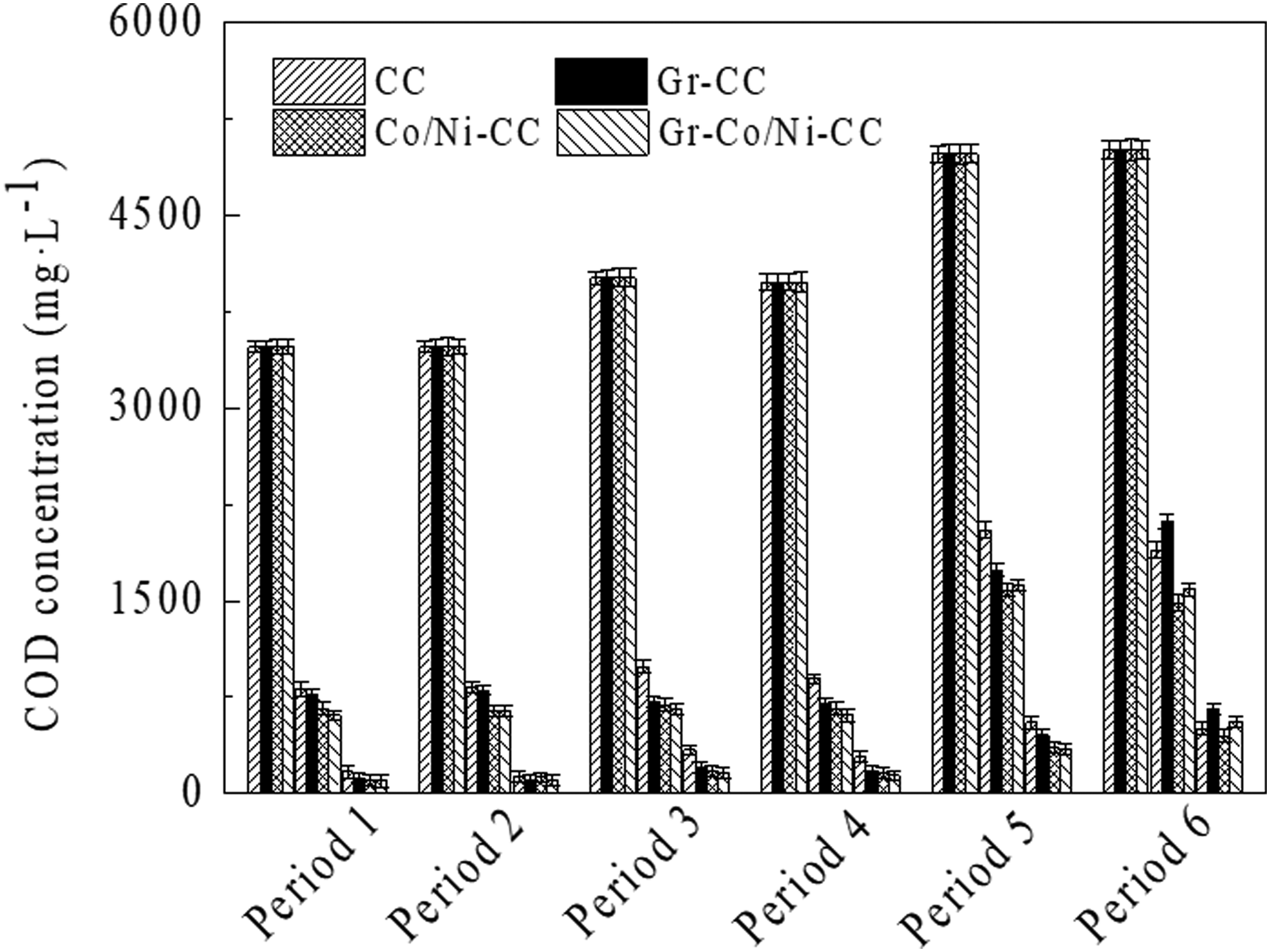
Removal of pollutants of MFCs with different anodes.
In a brief conclusion, these results indicated that the prepared Gr-Co/Ni-CC anode in this study not only posed high treatment efficiency on organics-rich wastewater but also improved the energy production performance.
Summaries
In this study, a Gr-Co/Ni-CC anode electrode was prepared using dip-coating method combined with hydrothermal process-air calcination method. As a comparison, CC, Gr-CC, and Co/Ni-CC electrodes were fabricated. Both the wrinkled and crumpled graphene sheets and granular substances were observed on the CC surface, proving graphene and Co/Ni were loaded on the CC surface. XRD patterns further illustrated that NiCo2O3 is the main form of the Co/Ni composite. Performance of different electrodes prepared in this study is illuminated as Table 2. It summarized that the excellent electrochemical performance of Gr-Co/Ni-CC electrode incorporated the low internal resistance and the high electrocatalytic activity. Moreover, the high MFC performance was achieved by equipping with the Gr-Co/Ni-CC. Compared with the control MFC systems, the highest maximum power density (784.89 mW/m2) and the lowest internal resistance (158.52 Ω) with Gr-Co/Ni-CC anode were obtained. The most significant aspect of the Gr-Co/Ni-CC anode was its high treatment efficiency in organics-rich wastewater, which inspired the possibility of using this material in the joint subject of waste treatment and bioenergy recovery.
(1) Electrochemical values were tested in 0.1 mol/L PBS solution and bioelectrochemical parameters were obtained at a resistance of 1,000Ω.
(2) A represented the day of the voltage output was stable, B represented the day of voltage output dropped dramatically, and C represented the total removal efficiency.
CC, carbon cloth; Co/Ni-CC, cobalt/nickel composite-carbon cloth; Gr-CC, graphene-carbon cloth; Gr-Co/Ni-CC, graphene-cobalt/nickel composite-carbon cloth.
Footnotes
Acknowledgment
This project was funded by the Science and Technology Department Project of Sichuan, China (2015SZ0009).
Author Disclosure Statement
No competing financial interests exist.