
Abstract
Abstract
There are many electronic components (ECs) in waste printed circuit boards (WPCBs), which can be reused if they can be dismantled without damage. At present, the popular thermal treatment would cause serious ECs damage and toxic gas leakage. In the chemical method, ECs can be dismantled by dissolving the tin solders without toxic gas leakage. But there is difficulty in choosing right chemical reagent to avoid discharge of wastewater, which obstructs its industrial application in recycling waste printed circuit board assemblies (PCBAs). In this article, ECs were dismantled by a mixture solution of hydrogen peroxide (H2O2) and fluoboric acid (HBF4), dissolving the tin solders on waste PCBAs. It was found that the tin solders were mildly dissolved at room temperature, and most of the ECs were preserved completely. Moreover, the mixture solution can be recycled to dissolve the tin solders repeatedly by supplementing H2O2, which avoided second pollution of fluoride wastewater discharge. So it is necessary to investigate the cyclic reaction mechanism of dissolving tin solders on waste PCBAs by a solder wire simulation system. It was observed that oxidation–reduction potential (ORP) of the solution changed regularly, and precipitate of copper corresponded to dissolution of tin with addition of H2O2. This is because copper, tin, and lead formed a microcorrosion cell, which promoted dissolution of solder wire effectively. And the ORP value can be used as an indication point for addition of H2O2 to recycle the mixture solution. The dissolution process was analyzed by mass distributions of tin, lead, and Cu in the solder wires, precipitate and solution, the E-pH diagram of Sn—H2O system, and the X-ray diffraction of precipitate. It was found that excessive amounts of H2O2 caused Sn2+ to form SnO passivation film at the beginning of the reaction. With decrease of pH value and oxidation degree, most of the tin formed SnO2 precipitate and lead formed Pb(BF4)2 in solution. SnO2 and PbO can be calcined to regenerate into SnO2 and PbO metallic oxide raw materials. The process provides an environmentally friendly method for industrial applications of recovering ECs, realizes reduction and reuse of WPCBs, and can further recycle Sn and Pb. It reflects the concept of circular economy and sustainable development.
Introduction
In recent years, waste electric and electronic equipment (WEEE) have become a global problem with the fast upgrading and renewing of electronic products. The printed circuit board assemblies (PCBAs), as an essential part of almost all WEEE, are growing at an average annual rate of 8.7% around the world, with China's growth rate of 14.4% (Huang et al., 2014; Zeng et al., 2017).
PCBAs are mainly composed of electronic components (ECs), tin solders, and plastic boards covered by metal layers, which contain many valuable metals. For example, the highest content used in the circuitry is Cu, followed by Sn, Fe, and Pb, which are used in the solder and lead frames. Au, Ag, and Pd are found in integrated circuits (ICs, a kind of ECs) as contact materials or plating layers due to their high conductivity and chemical stability (Hino et al., 2009). Many ECs in waste PCBAs are still functional and usable. They could bring more benefits if recycled properly (Lee et al., 2012). Correspondingly, some ECs such as cell batteries may ignite or leak potentially hazardous organic vapors if exposed to excessive heat or fire. Capacitors may also result in explosions when subjected to high currents and heating (Duan et al., 2011a). Thus, it is urgent to find the most efficient processes for the dismantling and removal of these assets, to minimize negative impacts on the environment.
In some previous research, traditional methods such as hydrometallurgical, pyrometallurgical, and mechanical processing were selected to recycle waste PCBAs. Biological methods (Mrážiková et al., 2016) and supercritical methods (Liu et al., 2016) were also studied in the laboratory. But these methods paid little attention to the ECs.
It is necessary to dismantle waste PCBAs effectively for recovery of tin solders and some ECs containing precious metals by controlling quality. And the possibility of tin solder contamination was eliminated in the final products (Achillas et al., 2013; Zeng et al., 2013). Disassembling ECs is the first essential step in waste PCBAs recycling chain (Wang et al., 2016). However, ECs such as chips, resistors, capacitors, and expansion slots are mounted onto the surface of the PCBs with tin solder. Some methods were researched to dismantle ECs by removing tin solders.
Usually, typical methods of dismantling ECs include heating technology, intelligent and automatic approaches, and chemical methods (Wa et al., 2005). The heating method is the main way of dismantling ECs from waste PCBAs in China currently. Figure 1 shows an actual operation picture of a factory worker. A tin bath was used to melt solder on waste printed circuit boards (WPCBs). In addition, some informal small workshops manually melt solders by a heat gun or a coal-heated plate (on the iron plate or flat wok) due to lower labor costs. But this way is seriously harmful to the health of employees due to the release of toxic gas, and processing rate is far from enough to satisfy industrial demand (Li et al., 2007; Huang et al., 2009). Therefore, semiautomatic and automatic thermal treatments with high-temperature gas, liquid heating, or infrared heater were widely studied in the past (Feldmann and Scheller, 1994; Yokoyama and Iji, 1997). The ultrasonic was also used to accelerate the melting and dropping of tin solders through ultrasonic vibrations (Huang et al., 2007). But the high-energy consumption, toxic gas leakage, and limited processing capacity obstruct these technologies as an industrial process for recycling waste PCBAs. Especially the bromine flame retardants will generate dioxins when PCBAs are heated to temperatures between 250°C and 400°C (Duan et al., 2011b). Moreover, the separation process of cutting components' pins will damage ECs and make them not to be reused. Actually, due to the complexity and high cost of equipment, automated methods can rarely be practiced, particularly in China (Li et al., 2014).

Removing solders on WPCBs with solder bath in a factory. WPCBs, waste printed circuit boards.
By comparison, in chemical method it is possible to dissolve tin solders using chemical reagents at room temperature and atmospheric pressure, which can avoid toxic gas leakage with relatively low cost. But there is difficulty in selecting a suitable chemical reagent that does not damage ECs. Some researchers used nitric acid, allyl sulfonic acid, hydrochloric acid, methanesulfonic acid, or Ti(IV) acid reagents to dissolve solders on WPCBs. Stennett and Whalley (2002) dissolved solders using a mixture of nitric acid and hydrogen peroxide (H2O2). Mecucci and Scott (2002) removed solders using nitric acid and iron nitrate. But nitric acid is a strong oxidizing and volatile acid. On the one hand, it dissolves not only solders but also other metals, which would consume extra acid and produce a different metal-dissolving solution. It is difficult to be further treated. On the other hand, its volatility will cause serious air pollution. Yang et al. (2016) could leach 99% of tin with SnCl4 and HCl at 60–90°C, and tin was then recovered from the purified solution by electrodeposition. But HCl volatility is also very strong. In addition, HCl will react with Pb to form PbCl2 precipitate on the surface of the solder to hinder the continuation of the reaction. Goodman et al. (2000) and Zhang et al. (2017) used methanesulfonic acid, hydrogen peroxide, and Ti(IV) acid to selectively dissolve the Sn–Pb solder. Zhang et al. (2017) also used fluoboric acid and hydrogen peroxide system to dissolve the tin solders. These chemical reagents can remove tin solders mildly, and ECs are hardly damaged. However, the leaching solution was not described to recycle, which will produce a lot of acidic wastewater. How to avoid second pollution of wastewater has to be solved.
In this work, the composite system of fluoboric acid (HBF4) and hydrogen peroxide was employed to dismantle ECs from waste PCBAs by dissolving tin solders. Fluoboric acid was taken as a leachant, and hydrogen peroxide was used as an oxidant (Zhang et al., 2015). The system was reused by adding H2O2, so the second pollution of fluoride wastewater was avoided. The cyclic reaction mechanism was analyzed. The aim is to develop an industrial cycle system, which is based on the HBF4/H2O2, to dismantle ECs in WPCBAs nondestructively and environmentally friendly.
Experimental
Materials
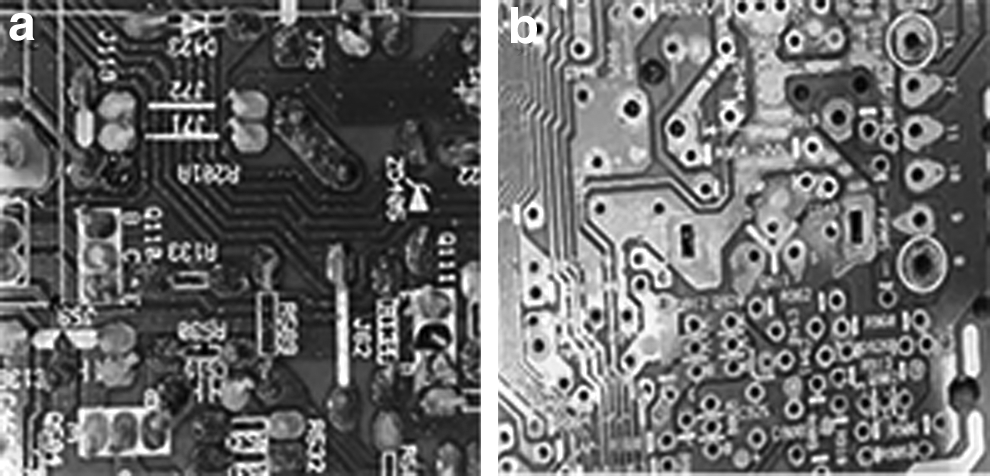
Waste PCBAs used in this study were the television boards from a solid waste disposal center of Shanghai, China. It contained polymer materials, glass fibers, metals, and ECs. ECs were mounted by the tin solders (lead [37%]/tin [63%], [wt%]) (shown in Fig. 2a, b). The waste PCBAs were cut into ∼5 × 10 cm fragments with a scissor before conducting the experiment. Fluoboric acid (HBF4, 48%), hydrogen peroxide (H2O2, 30%), copper sheet (Cu, AR) (Fig. 2c), and other reagents were all obtained from Sinopharm Chemical Reagent Co., Ltd. and used without any further treatment. The solder wire (lead [37%]/tin [63%], [wt %]) (Fig. 2d) was obtained from Guangdong Zhongshi Metals Co., Ltd. SiC papers with 2000 mesh were used to polish the surface of the solder wire, rinsing them with deionized water.
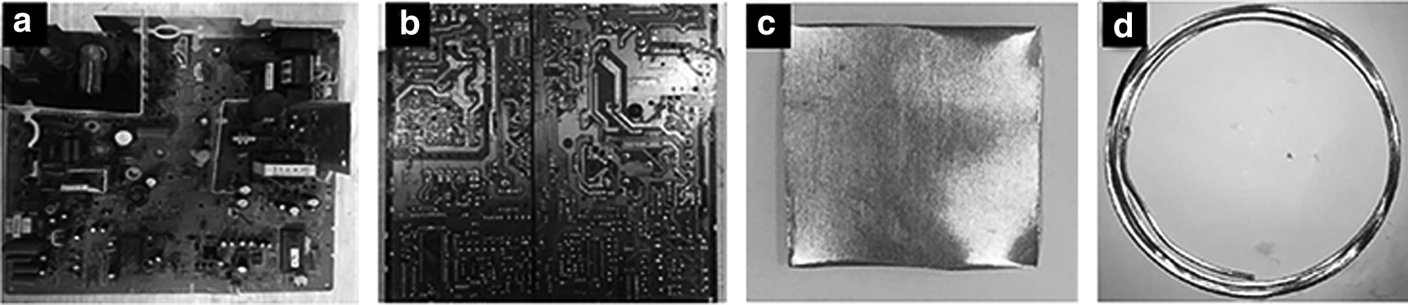
Experimental materials:
Procedures
The waste PCBAs system: HBF4 and H2O2 were mixed at a certain ratio and were put into a 8 × 12 cm polytetrafluoroethylene vessel with a magnetic stirrer. Then, a waste PCBAs fragment was laid flat into the vessel. The level line of the chemical solution was sufficient to submerge the polymer board containing the solder side rather than the ECs side, which would prevent ECs from damage by the chemical agents as far as possible. The ECs would be liberated after the solder had been dissolved. The first waste PCBAs were taken out after the tin solders had been dissolved completely. Then, the second waste PCBAs were put into the vessel, and a certain volume of H2O2 was added. The solution system was reused to leach waste PCBAs. The experimental phenomena were recorded.
The simulation system (with or without copper sheet): It involved dissolving 35 g new solder wires (and 7 g copper sheet) in a mixture of HBF4 and H2O2 in a 100 mL polytetrafluoroethylene beaker with a magnetic stirrer. The 20 same samples were reacted simultaneously. The pH value of solutions was real time investigated by a pH meter (FE28; Mettler Toledo). The BF4- of solutions and the oxidation–reduction potential (ORP) were real time monitored by an automatic potential titrator (ZD-2, Rex; Shanghai INESA Scientific Instrument Co., Ltd.) with a fluoroborate ion selective electrode (PBF4-1, Rex; Shanghai INESA Scientific Instrument Co., Ltd.) and an ORP electrode (501, Rex; Shanghai INESA Scientific Instrument Co., Ltd.). A certain volume of H2O2 was added to the solution when the ORP dropped to the lowest point. Each sample was stopped with 1-h interval.
Then, the reaction solution was filtered. The residual solder wires and precipitate (there is also residual copper sheet if it was the simulation system with copper sheet) were separated from the solution. The mass of the residual solder wires, residual copper sheet and precipitate were weighed with balance, respectively. Then, they were digested with microwave (XT-Mul; Shanghai Xintuo Analysis Instrument Technology Co., Ltd.), respectively. Then, ∼1 μL sample solution was collected from the two digestion solutions and residual solution to determine tin and lead (and copper) using an ICAP 6300 inductively coupled plasma-atomic emission spectrometer (ICP-AES, Prodigy; LEEMAN Company). The data were determined three times to obtain the average values. The composition of solid precipitate was examined by X-ray diffraction (XRD, 18KW D/MAX2500V; Rigaku Corporation), and the gases released during the reaction were determined by Gas Chromatography (GC) (nitrogen as carrier gas, using 5A molecular sieve detection column, TCD detector, SP7800; Beijing Zhong Teach Jin Yuan Co., Ltd.).
Results and Discussion
Cyclic reaction of mixture solution dissolving tin solders to dismantle ECs from waste PCBAs
First, the relation between the reaction time and volume ratio of HBF4 and H2O2 was determined. It can be observed from Fig. 3 that the reaction time is shortest when volume ratio of HBF4 and H2O2 is ∼5:3. The ECs are perfectly removed in ∼60 min.
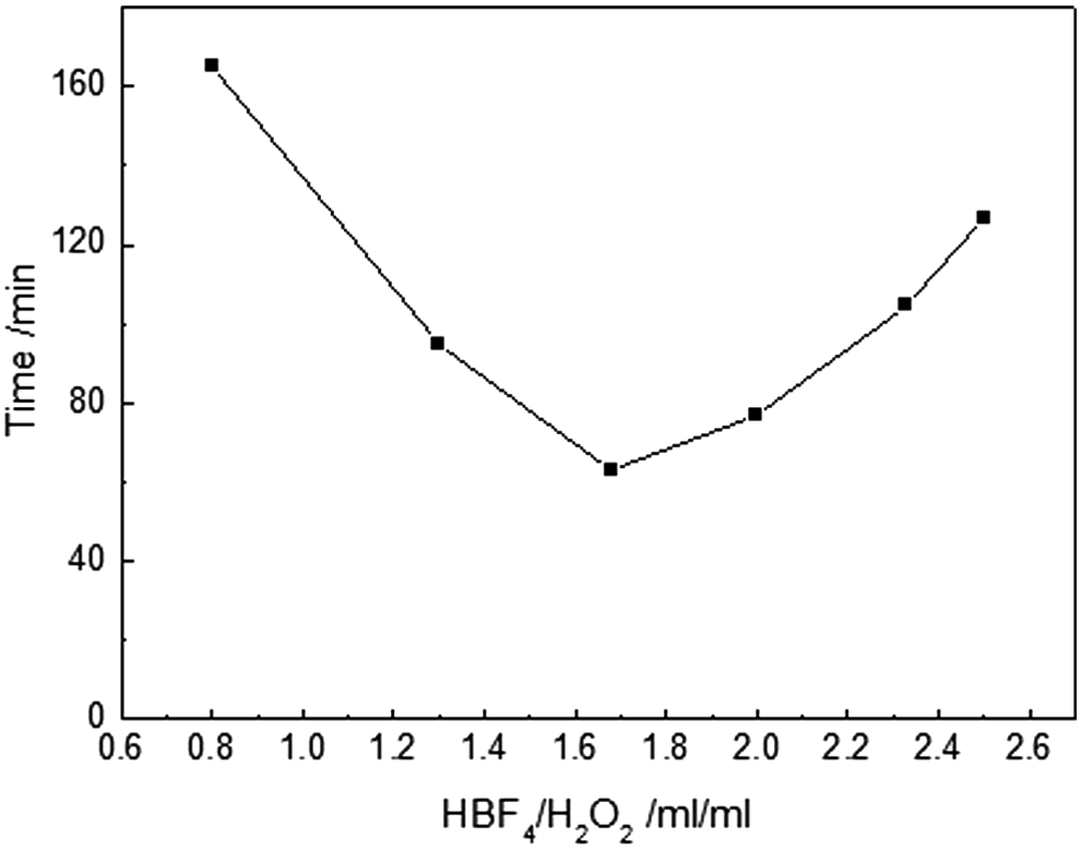
Relation between the reaction time and volume ratio of HBF4 and H2O2. H2O2, hydrogen peroxide.
To avoid the production of wastewater, the cyclic experiments of dissolving tin solders to dismantle ECs from waste PCBAs were investigated. Figure 4 shows waste PCBA fragments before and after dismantling ECs in seven times cyclic dissolving tin solders processes. It can be seen that the ECs have been perfectly removed. While it was found that the mixture solution of HBF4 and H2O2 could be reused to dissolve tin solders by adding 20% H2O2, which avoided the discharge of wastewater. In addition, some precipitates were produced in the solution during the reaction. Figure 5 shows that the volume of precipitates increases with increasing cyclic numbers and the color is different for each reaction. Another interesting thing is that the copper in the waste PCBAs was dissolved at the beginning of the reaction, precipitated on the tin solder pins during the reaction, and removed again at the end of the reaction (shown in Fig. 6).
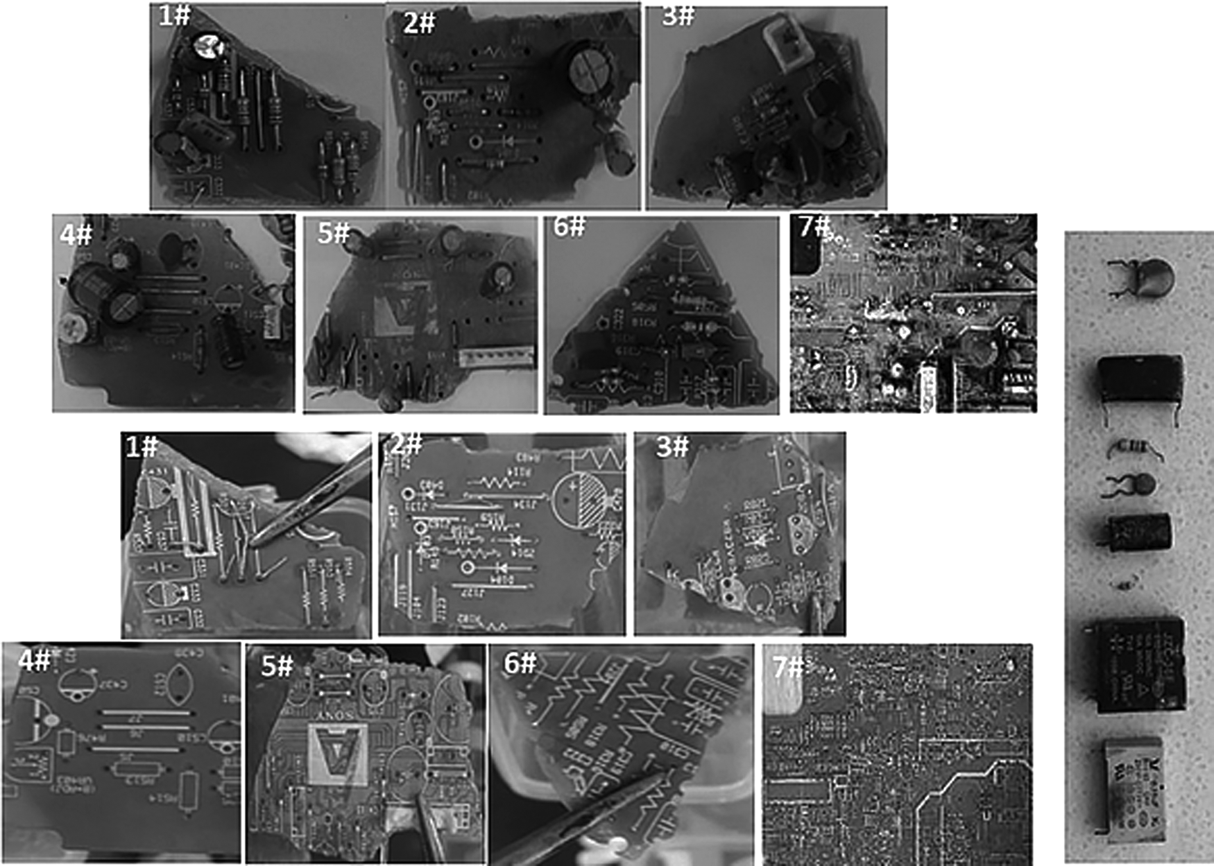
Waste PCBA fragments before and after dismantling ECs in seven times cyclic dissolving tin solders processes.
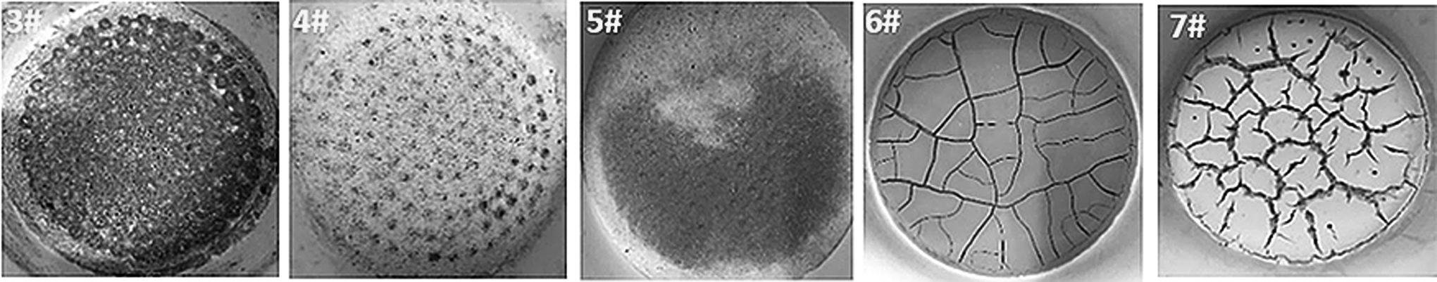
Precipitate of dissolving tin solders on waste PCBAs.
In addition, tin solders can be dissolved continuously in the seven cyclic reactions without adding HBF4. To reuse the mixture solution and find an industrialization approach of dismantling ECs from waste PCBAs, the cyclic dissolution mechanism has been studied. As the mechanism will be influenced by many unimportant factors if waste PCBAs were used, the simulation system of dissolving solder wires was investigated.
Cyclic reaction mechanism of mixture solution dissolving solder wires
It has been found from the above dissolving tin solders in the waste PCBAs system that H2O2 must be added after a cyclic reaction finished in order to continue dissolving tin solders by the solution. It indicates that oxidation of H2O2 is the key to the cyclic reaction, so ORP was real-time monitored in the dissolving solder wires simulation system. In addition, copper played an important role in the actual system, so the experiments of dissolving solder wires were operated in the presence and absence of copper.
Figure 7 shows the changes of ORP, pH, and BF4- concentration of solutions with reaction time in the presence and absence of copper. It can be observed from Fig. 7a that ORP changes are both very little within ∼11 h in the absence and presence of copper. Then, ORP changes regularly and greatly in the presence of copper but still very little in the absence of copper. It is considered that the amount of H2O2 was enough to maintain the oxidation of the system at the initial stage of reaction. But with the prolongation of reaction time, the dissolution rate of solder wire was very slow in the absence of copper. It resulted in limited consumption of H2O2, making little change to ORP, slow decrease of acidity and BF4- concentration (shown in Fig. 7b, c). By contrast, the dissolution of solder wire was promoted effectively in the presence of copper, which caused a rapid consumption of H2O2. Figure 7a shows that ORP drops to the lowest point, and first added H2O2 was consumed completely to need to be added when the reaction time reached 13.5 h (the dotted vertical lines). The ORP changes regularly and greatly with addition of H2O2 in the subsequent reaction time. The pH value increases rapidly from ∼−0.7 to 0.6 in 3 h of initiation (shown in Fig. 7b), and then remains the same basically. Figure 7c shows that the magnitude of BF4- concentration decrease is greater in the presence of copper than in the absence of copper. After 20 h, 35 g solder wires had been dissolved in the presence of copper. But only ∼10 g solder wires had been dissolved in the absence of copper. It is deduced that copper acted as a reaction catalyst. Changes of pH value and BF4- concentration need to be analyzed by some extra data in the presence of copper. Therefore, the mass distributions of tin, lead, and Cu in the solder wires, precipitate, and solution were determined, and the reaction mechanism was further analyzed.
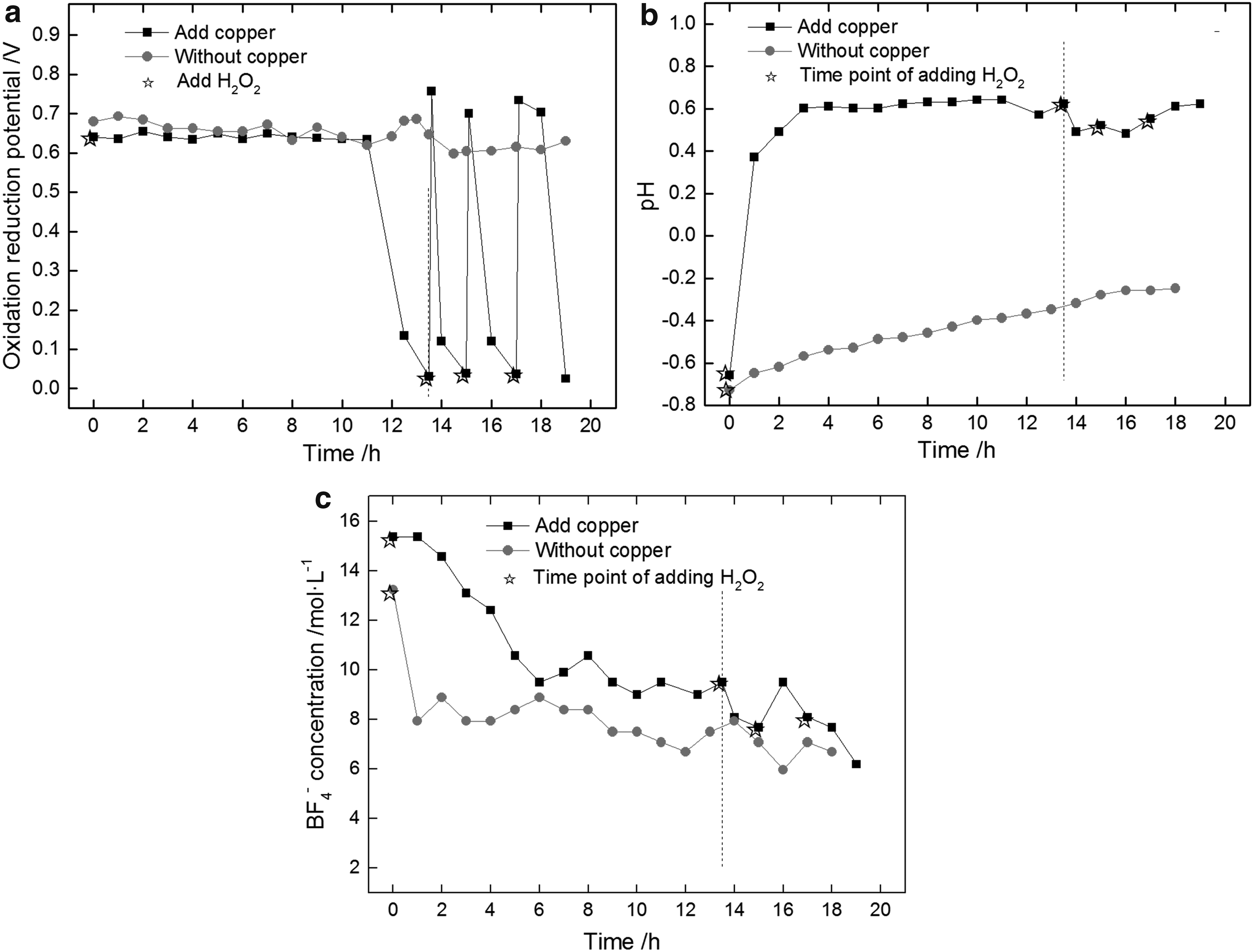
Figure 8a shows that tin and lead in the solder wires were dissolved gradually with reaction time, but the copper mass varies little before 13.5 h. It is because reducibility of tin and lead is stronger than that of copper, which makes H2O2 oxidation easier. The reaction can be expressed as Equations (1)–(4) (Behnamfard et al., 2013). The displacement reaction of Equations (5) and (6) happened after H2O2 being consumed completely, and copper was precipitated as shown in Fig. 6a (Kim et al., 2014). The amount of dissolved copper in the solution was so less that the displacement reaction finished quickly and ORP dropped to the lowest point in 13.5 h. Correspondingly, the amount of tin and lead in the solution increased (the dotted vertical lines shown in Fig. 8b). The reaction process was repeated by adding H2O2 after 13.5 h. It can be observed from Figs. 7a and 8b that ORP changes regularly, and the precipitate of copper corresponds to dissolution of tin with increasing addition of H2O2. It can also be seen from Fig. 8b and c that lead mass increases greatly and tin mass hardly increases in the solution, meanwhile lead mass increases little, tin mass increases greatly, and copper sheet was converted into copper precipitate in the precipitate. It can be considered that copper, tin, and lead formed a microcorrosion cell to accelerate the dissolution of the solder wires. The dissolution reaction of lead can be expressed as Equations (7) and (8) (Jha et al., 2012). There is a dynamic equilibrium between PbO and Pb(BF4)2, and Pb(BF4)2 is dominant:
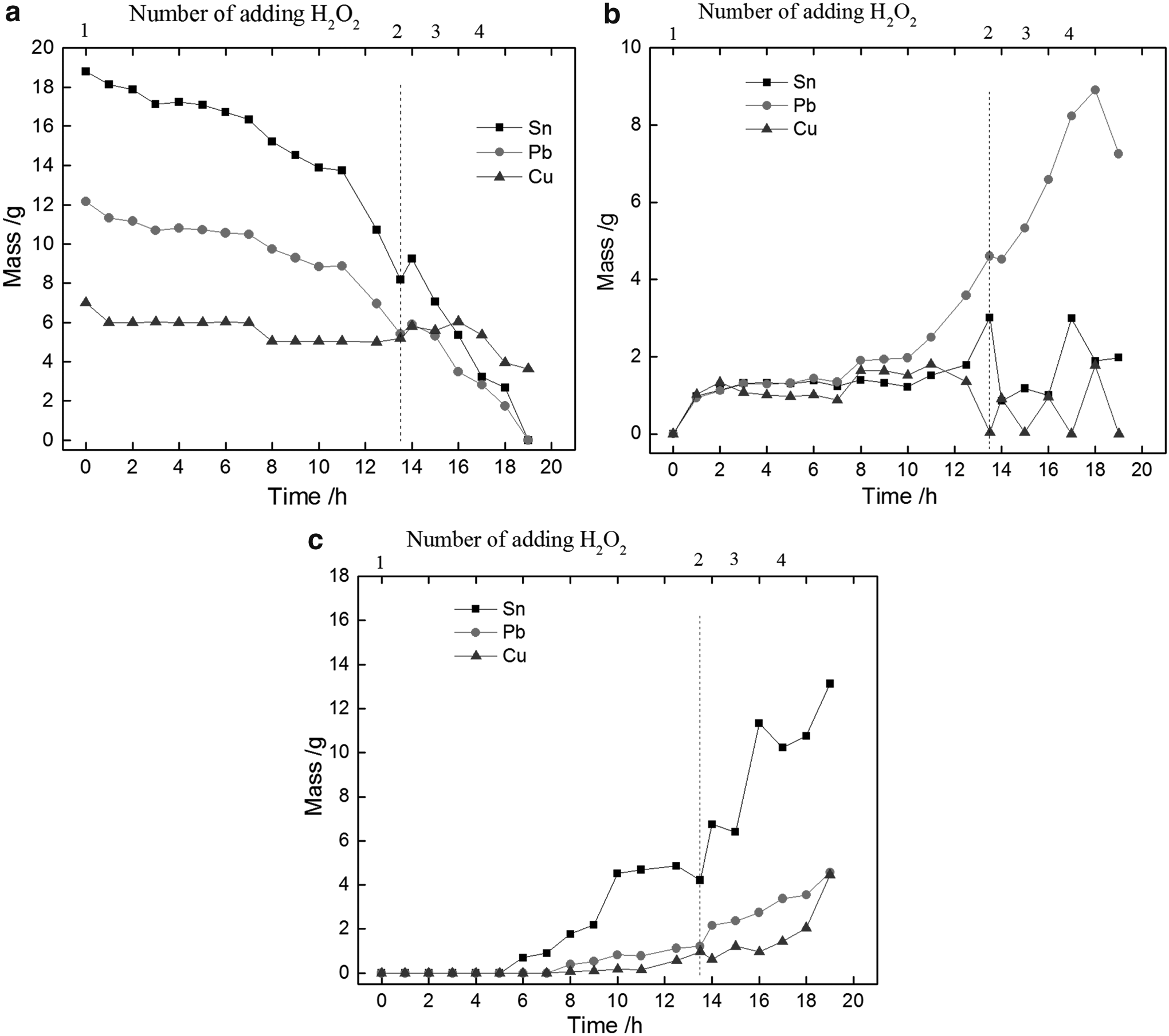
Mass changes of Cu sheet and Sn, Pb
Tin changes can be analyzed as shown in Figs. 9–11. It is shown in Fig. 9 that some color changes are observed on the solder wire surface during the reaction. It is considered that the reactions in Equations (9)–(13) occurred according to the physical and chemical properties of tin. Figure 10 is drawn by HSC 6.0 according to the experimental conditions. It can be observed that Sn changes into Sn2+ and Sn4+ with the increase of ORP. It is because the excessive amounts of H2O2 at the initial stage of reaction resulted in a high ORP (Fig. 7a shows ∼0.65 V), which enhanced the oxidizing ability of the dissolving solution. This case in turn caused the rapid increase of Sn2+ ion concentration in the local area, resulting partly in the formation of Sn(OH)2 from Sn2+ [Eq. (9)]. Sn(OH)2 easily dehydrates to form SnO [Eq. (10)], which is a black passivation film shown in Fig. 9b. As the two valence tin is unstable in high ORP, Sn(OH)2 was oxidized into white precipitate Sn(OH)4 [Eq. (11)], which mixed with SnO to form a gray film shown in Fig. 9c (Cotton et al., 1999). And the other Sn2+ was oxidized into Sn4+ [Eq. (12)], which in turn formed Sn(OH)4 with decrease of pH value [Fig. 10 and Eq. (13)] (Abd El Rehim et al., 2006). It can be observed from Equation (13) that H+ is released causing acidity equilibrium of the solution, hence pH value in Fig. 7b can be maintained at 0.6 to make the dissolution of the solder wire continuous. Figures 7a, 10, and 11 and Equation (14) show that ORP decreased with increasing reaction time, which made Sn(OH)4 dehydrate form SnO2·H2O (Abd El Rehim et al., 2006). It can be observed from Fig. 8b and c that some tins are in the solution though most of the tins formed SnO2 precipitate. It can be observed in Equations (15)–(18). Some Sn(OH)2, SnO, and Sn(OH)4 reacted with HBF4 to form Sn(BF4)2 and Sn(BF4)4, respectively. And some tins reacted with each other:
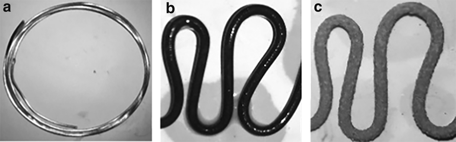
Color changes on the solder wire surface:
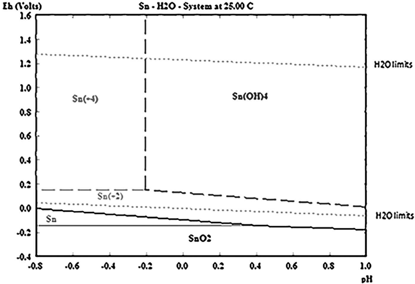
E-pH diagram of Sn—H2O system, 25°C.
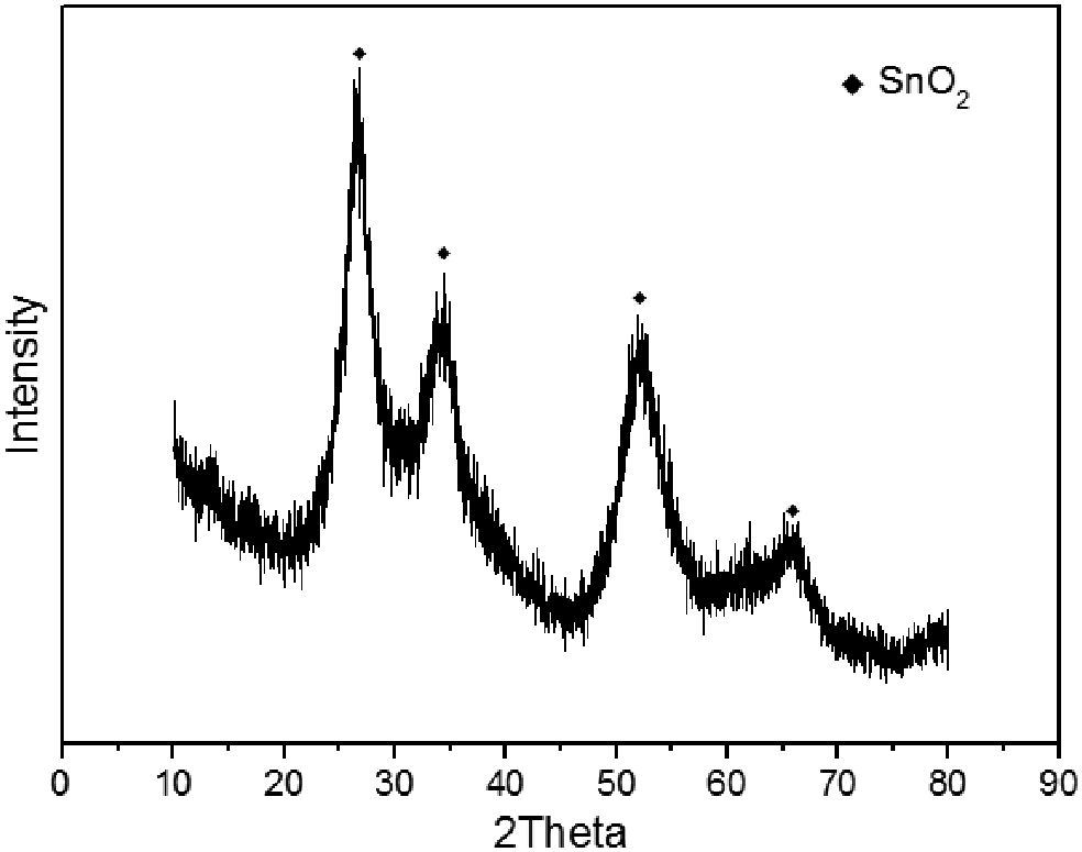
XRD of precipitate. XRD, X-ray diffraction.
It can be observed from the above equations that BF4- reacted with tin and lead to form Pb(BF4)2, Sn(BF4)2, and Sn(BF4)4 in the solution. But it was found during the experiment that the solution temperature can rise >60° at the beginning of the reaction because of intense redox reaction. It may lead to hydrolysis of HBF4. The reaction can be expressed as Equations (19)–(21) (Zhang and Chen, 1989; Xu et al., 2007). So it can be observed from Fig. 7c that the BF4- concentration decreases rapidly, then the trend slows down with decreasing reaction temperature. Analysis of GC indicated that the released gases contained HF. It can be absorbed by alkali liquors. Therefore, HBF4 can be added to make reaction continue when consumed completely:
In summary, it is feasible that the mixture solution of HBF4 and H2O2 is used to dismantle ECs from waste PCBAs by dissolving tin solders. HBF4 and H2O2 are supplemented when consumed completely. There is no wastewater discharge. The method is environmentally friendly.
Conclusion
In this article, the composite system of HBF4 and H2O2 was employed to dismantle ECs from waste PCBAs by dissolving tin solders. The experiment found that ECs can be removed perfectly, and the solution can be reused by adding HBF4 and H2O2. The method avoided second pollution of fluoride wastewater discharge. The cyclic reaction mechanism of dissolving the tin solders on waste PCBAs was investigated by a solder wire simulation system. It was found that copper played an important role in dissolving the solder wires, which promoted the dissolution of solder wire effectively because copper, tin, and lead formed microcorrosion cell. The consumption of H2O2 was large, which was a key to maintain the cyclic reaction. ORP value can be used as an indication point for addition of H2O2 to recycle the mixture solution. The reaction precipitate was analyzed by XRD, and it was SnO2 mainly.
Therefore, the dissolution processes of the metals were discussed by the mass distributions of tin, lead, and Cu in the solder wires, precipitate and solution and the E-pH diagram of Sn–H2O system. The results indicated that tin was oxidized from Sn2+ to Sn4+. In the end, most of Sn(OH)4 dehydrated to form SnO2 precipitate because of low acidity, and a few formed Sn(BF4)4 in the solution. By contrary, most of the lead formed Pb(BF4)2 in the solution, and a few formed PbO precipitate, which has a dynamic equilibrium between PbO and Pb(BF4)2.
Footnotes
Acknowledgments
The authors are grateful for support of Program of Innovative Research Team in University (IRT13078), Science and Technology Planning Project of Guangdong Province, China (2017B030314175), the Research Fund of Shaanxi Key Laboratory of Comprehensive Utilization of Tailings Resources (Shangluo University), the Funds of Jiahua Science and Technology Bureau (Grant No. 2013-3-001), and the Funds of Jinhua Environmental Protection Bureau (Grant No. YG2014-FW673-ZFCG046).
Author Disclosure Statement
No competing financial interests exist.