
Abstract
Purpose:
To determine the targeting error of a novel stereotactic prostate biopsy system that integrates preinterventional MRI with peri-interventional ultrasonography (US) for perineal navigated prostate biopsies.
Materials and Methods:
We performed stereotactic biopsies on five prostate phantoms (one CIRS 053-MM and four CIRS 066). Phantom 053-MM incorporates three MRI- and transrectal ultrasonography (TRUS)-visible lesions, while lesions within phantom 066 are only detectable on MRI. In both phantoms, the 0.5 cc volume lesions are placed randomly. The phantoms were examined by 3T-MRI preinterventionally. Then three stereotactic biopsies from one lesion in phantom 053-MM and from all US-invisible lesions in the 066 phantoms were taken under live-fusion imaging guidance. During intervention, a mix of blue ink and gadobutrol was injected into each biopsy channel. Afterward, another 3T-MRI was obtained. These MRI images were then fused again with the intraoperative TRUS data. Thus, the targeting error (TE) between the planned and performed biopsy cores could be measured. In addition, the procedural targeting error (PTE) between the virtually planned biopsy trajectory and the manually registered three-dimensional needle position of every single biopsy core taken was calculated.
Results:
The overall TE of the 39 biopsy cores taken was 0.83 mm (standard deviation [SD]: 0.48 mm) with the highest TE in the sagittal plane (1.09±0.54 mm), followed by the coronal (0.72±0.43 mm) and axial (0.69±0.34 mm) planes. The procedural TE, which is provided intraoperatively, was 0.26 mm on average (SD: 0.46 mm). Comparing PTE and TE, there was no statistically significant difference (P=0.39).
Conclusion:
The TE of stereotactic biopsies using our novel perineal prostate biopsy system is below 1 mm and can be estimated in vivo by the automatically calculated procedural TE. Thus, stereotactic prostate biopsies guided by the combination of MRI and US allow effective and precise examination of MRI lesions.
Introduction
In their landmark studies, Barzell and associates 5 and Onik and colleagues 6 have described perineal prostate mapping biopsies as an appropriate method for optimal staging of localized PC. More recently, Crawford and coworkers 7 also reported their experience with mapping biopsies and their influence on further treatment decisions. Publication of final correlative data between mapping biopsies and radical prostatectomy specimen from this group is under way and was presented at the 2011 American Urological Association Annual Meeting showing only minimal upgrading. Mapping biopsies, however, necessitate a very high number of cores (approximately 56 cores) per patient and frequently cause urinary retention.
Multiparametric MRI has the potential to guide biopsies to the most aggressive cancer foci in patients with previously negative biopsies, increasing the accuracy of the procedure. 8 Multiparametric MRI allows detection of PC with a sensitivity range of 66.7% to 92% and a specificity range of 89% to 100%, depending on size and grading. Roethke and colleagues 9 have reported sensitivities of prostate MRI from 26% in lesions <5 mm up to 89% in lesions >20 mm. Lately, Turkbey and associates 10 found a positive predictive value of multiparametric MRI in up to 98% in lesions >5 mm.
The use of MRI in PC management, however, is still controversial. 8,11 Magnetic resonance (MR)-guided biopsies are not feasable in the clinical routine because of limited availability, limited number of cores, and reduced ergonomy. 8,12 –14 Therefore, a combination of ultrasonography (US) and MRI might result in a practicable alternative; such approaches have been reported, 15 –19 typically as prototypes or at an experimental stage. The main drawback of most systems is that they use delicate electromagnetic tracking, which is highly susceptible to metallic and magnetic interferences, reducing precision.
In this context, we have described the development of a novel prostate biopsy system that integrates preinterventional MRI data with peri-interventional US for perineal prostate biopsies (BiopSee,® MedCom, Darmstadt, Germany). 20 BiopSee is the first platform available for clinical routine that integrates imaging, TRUS/MRI fusion, biopsy-planning, perineal targeting, and precise three-dimensional (3D) mapping into a single system. The calculated procedural targeting error (TE) of the first 106 consecutive patients was 1.7 mm on average (standard deviation [SD]: 1.7 mm).
We report on phantom studies to exactly determine the TE of the BiopSee system.
Materials and Methods
Phantom
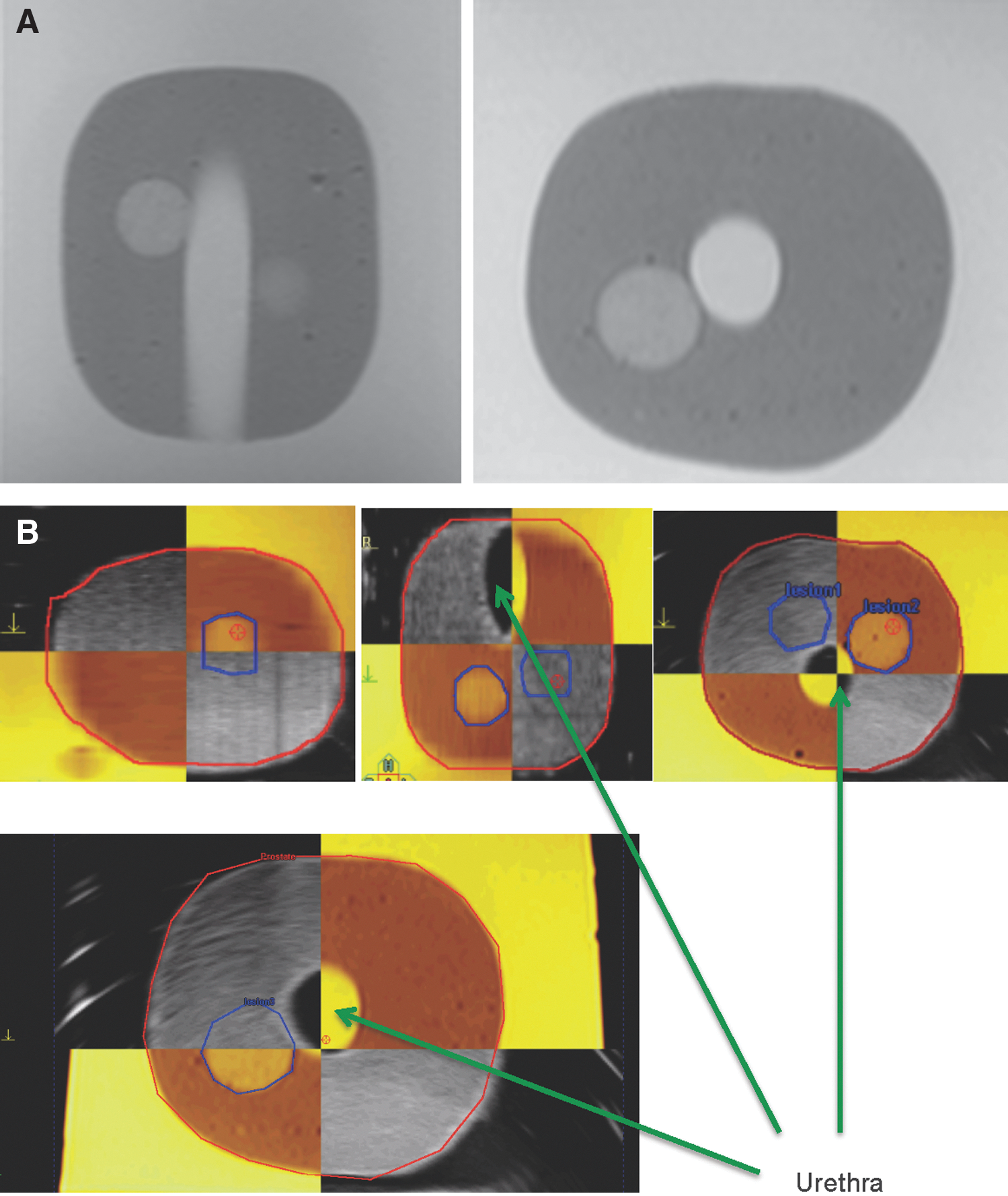
We performed stereotactic biopsies on five prostate phantoms (CIRS 053-MM and CIRS 066, CIRS Inc., Norfolk, VA). The CIRS 053-MM phantom consists of three randomly placed lesions of 1 cm in diameter (0.5 cc volume), which are visible in MRI and TRUS. The CIRS 066 phantom consists of the same number and size of lesions, but these lesions are only visible on MRI and are isoechoic on US.
MRI
The phantom measurements were carried out at three Tesla (3T)-MRI pre- and postinterventionally at a 3.0 Tesla MR scanner (Magnetom Trio; Siemens, Erlangen, Germany). First, half-Fourier acquisition turbo spin echo (TSE) sequences for planning of slice angulations of the following T2-weighted TSE sequences were obtained. Sequence parameters for the transversal/sagittal T2-weighted TSE sequences were: TR 6260 (ms), TE 148 (ms), field of view (FoV) (222×224) (mm2), slice thickness 1.5 (mm), averages 3 (n), acquisition time (TA) 4:49 (min:sec); the resulting voxel size was 0.5*0.6*1.5 (mm3). Turbo factor was 13 each and GRAPPA (Generalized Autocalibrating Partially Parallel Acquisition) 21 was applied as a parallel imaging technique. Parameters for the coronal T2-weighted TSE sequence were: TR 6260 (ms), TE 148 (ms), FoV (183x224) (mm2), slice thickness 1.5 (mm), averages 3 (n), TA 5:46 (min:sec); the resulting voxel size was 0.5*0.6*1.5 (mm3). Echo train length was 15. Analogue to the transversal/sagittal sequences, GRAPPA was applied as a parallel imaging technique.
Biopsy
The BiopSee system consists of a personal computer with an integrated ultrasound device and additional electronics for controlling position and orientation of the ultrasound probe. The probe itself has a custom-made biplane endorectal design with 150-degree transversal and 70-mm longitudinal FoV (Telemed, Vilnius, Lithuania). Each of the arrays consists of 128 elements. The maximum available frequency is 8 MHz for the transversal plane and 10 MHz for the longitudinal one.
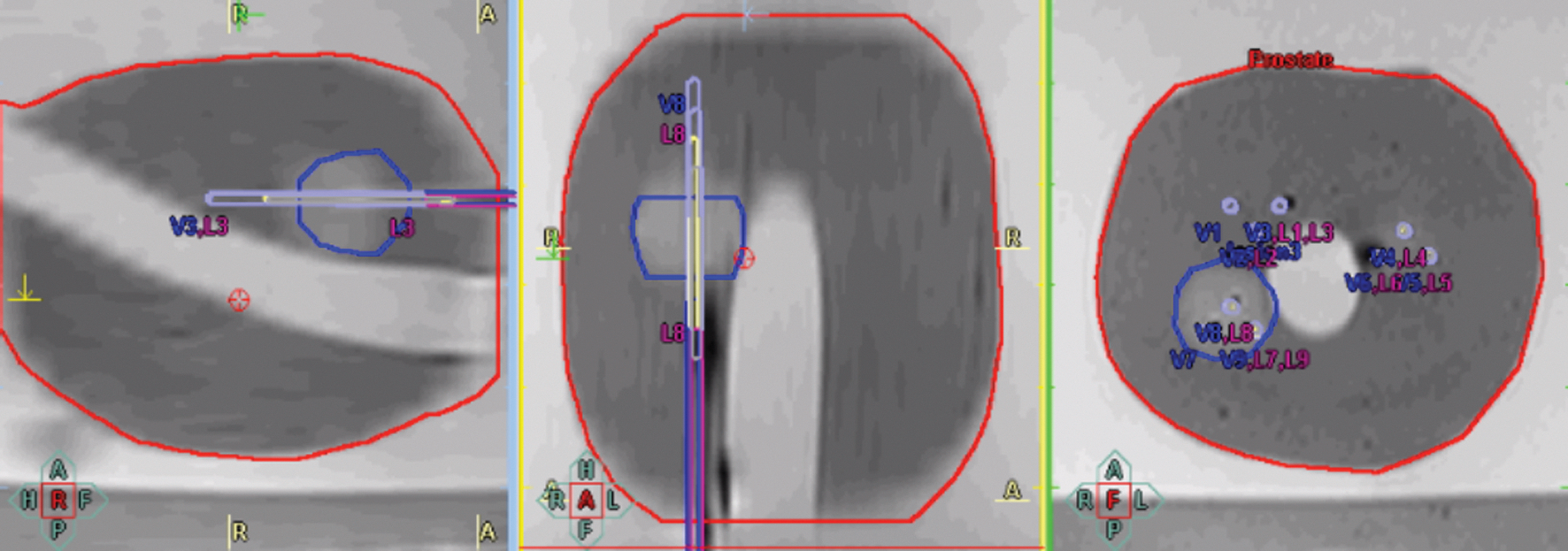
During the procedure, the ultrasound probe is placed on a custom-made mechanical stepper that is fixed to the operating table and has two degrees of freedom: One can adjust probe depth and rotation of the probe along its main axis. Both movement and rotation are tracked by two built-in encoders connected to the personal computer. For needle insertion, a grid is attached to the stepper (Fig. 1).
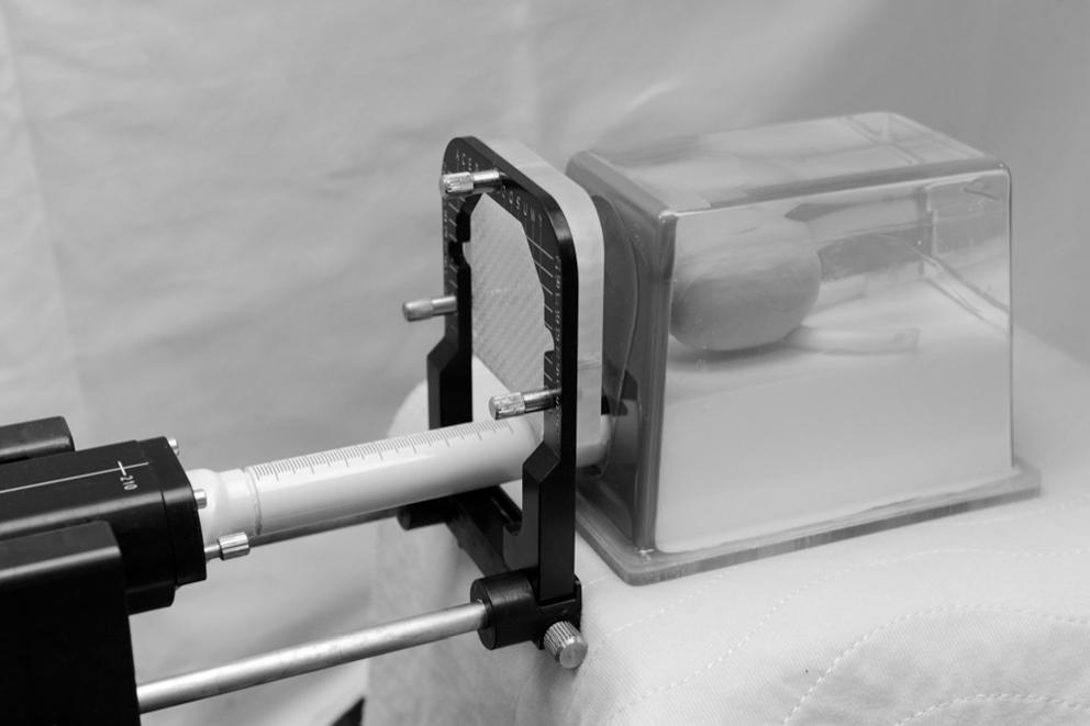
Biopsy setup.
During intervention, 3D-US is acquired first by recording a series of transversal two-dimensional (2D) images while moving the probe from cranial to caudal, resulting in a 3D-dataset. T2w-MR images with marked lesions are imported via Digital Imaging and Communications in Medicine (DICOM) interface. Having both 3D volumes in the system, the registration is performed. Currently, the relation between the MR and US is defined as a rigid transformation having six degrees of freedom (three for translation and three for rotation). There is no scaling, because the MR geometry is known from the DICOM data and the ultrasound device is integrated in the system and the frame size is known, too. Two volumes are registered manually based on the MR contour overlay over the U/S dataset. The application visualizes a mix of the two volumes in axial, coronal, and sagittal planes. This allows transferring lesions marked on the diagnostic MRI scan over the intrainterventional US dataset (Fig. 2).
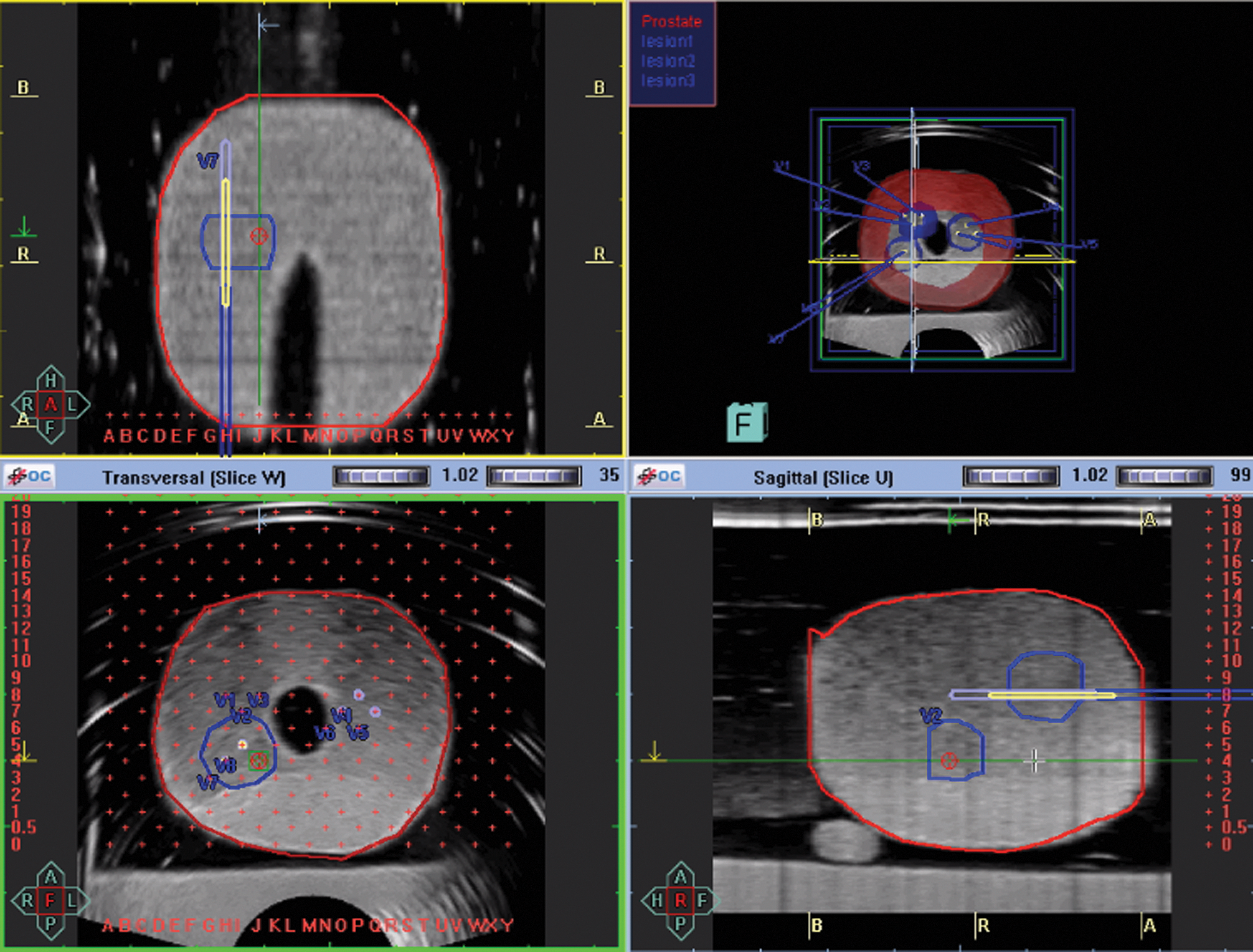
Next, biopsy cores are placed virtually within the 3D-dataset (Fig. 3). During the biopsy procedure, one after the other desired biopsy cores are selected, and the user first navigates the ultrasound probe to that position; ie, he or she rotates the ultrasound transducer until the longitudinal plane crosses the virtual needle insertion line. The US is overlaid by organ and lesion contours as well as by the planned needle trajectory (Figs. 3 and 4); thus, real-time navigation is established in a way that deviations from the target become instantaneously visible on the screen and can be corrected on the fly, enabling positioning of the needle with high accuracy.
Planning of biopsies in isoechoic; MRI-only visible lesions in a CIRS 066 phantom.
Live ultrasonography and registration of a stereotactic biopsy.
Biopsies are taken with an 18-gauge needle with a length of 240 mm (Uromed Ltd., Oststeinbek, Germany) and a maximum sample length of 19 mm. After each biopsy, the exact needle position is manually registered and stored together with orientation data (2D- and 3D-topograms, longitudinal and transversal US views) for documentation purposes. Comparing the virtually planned biopsy trajectory and the manually registered 3D needle position of every single biopsy core taken, the procedural targeting error (PTE) between the planned and documented biopsy in X, Y, and Z planes is calculated by the system.
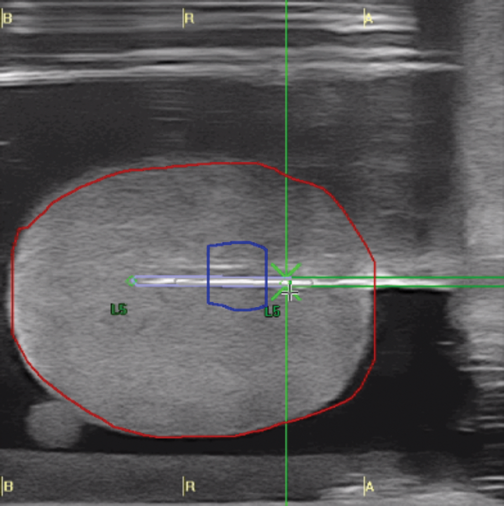
During intervention, a mix of blue ink and MR contrast agent was injected into each biopsy channel. An MR contrast agent gadobutrol (Gadovist,™ Bayer, Germany) was administered (1:20 dilution). Afterward, 3T-MRI with the parameters mentioned above was obtained again. These postinterventional MR images were then transferred back to the biopsy system and matched with the previous contours (Fig. 5). Thus, the target registration error between the planned and performed biopsy cores was measured in the fusion images (Fig. 6).
Postinterventional MRI matched with the intrainterventional contours and registered biopsy trajectories.
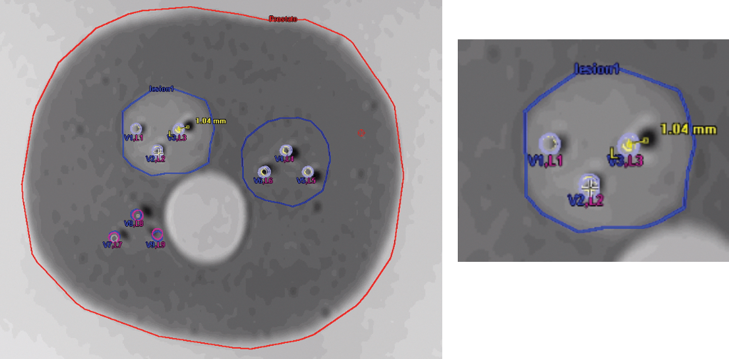
Measurement of the targeting error on postinterventional MRI matched with the preinterventionally planned trajectories and intrainterventionally registered biopsies (with detail of upper left lesion).
Statistics
Statistical analyses were performed using Prism (Graphpad, La Jolla, CA). P<0.05 was considered significant.
Results
All biopsies were on target. The PTE between the virtually planned biopsy trajectory and the manually registered 3D of the 39 performed biopsies was 0.26 mm on average (SD: 0.46 mm) (Figs. 7/9A). The highest deviation between planned and registered coordinates was in the sagittal plane (0.51±0.71 mm), followed by the coronal (0.16±0.15 mm) and axial (0.12±0.1 mm) planes. To validate the automatically calculated PTE, postinterventional MR images were matched with the intrainterventional contours and planned biopsy trajectories (Fig. 5). In these images, we measured the deviation between planned and performed biopsies and documented in the postinterventionally acquired MRI scans (Fig. 6). We found a TE in this matching of the performed 39 biopsies of 0.83 mm (SD: 0.48 mm). The highest TE was measured in the sagittal plane (1.09±0.54 mm), followed by the coronal (0.72±0.43 mm) and axial (0.69±0.34 mm) planes. The TEs of each biopsy are shown in Figs. 8/9B. Comparing PTE and TE in paired samples, there was no statistically significant difference (P=0.39, Wilcoxon signed-rank test). The results were normally distributed. Thus, the system's software-calculated error might serve as an approximation for the actual TE.
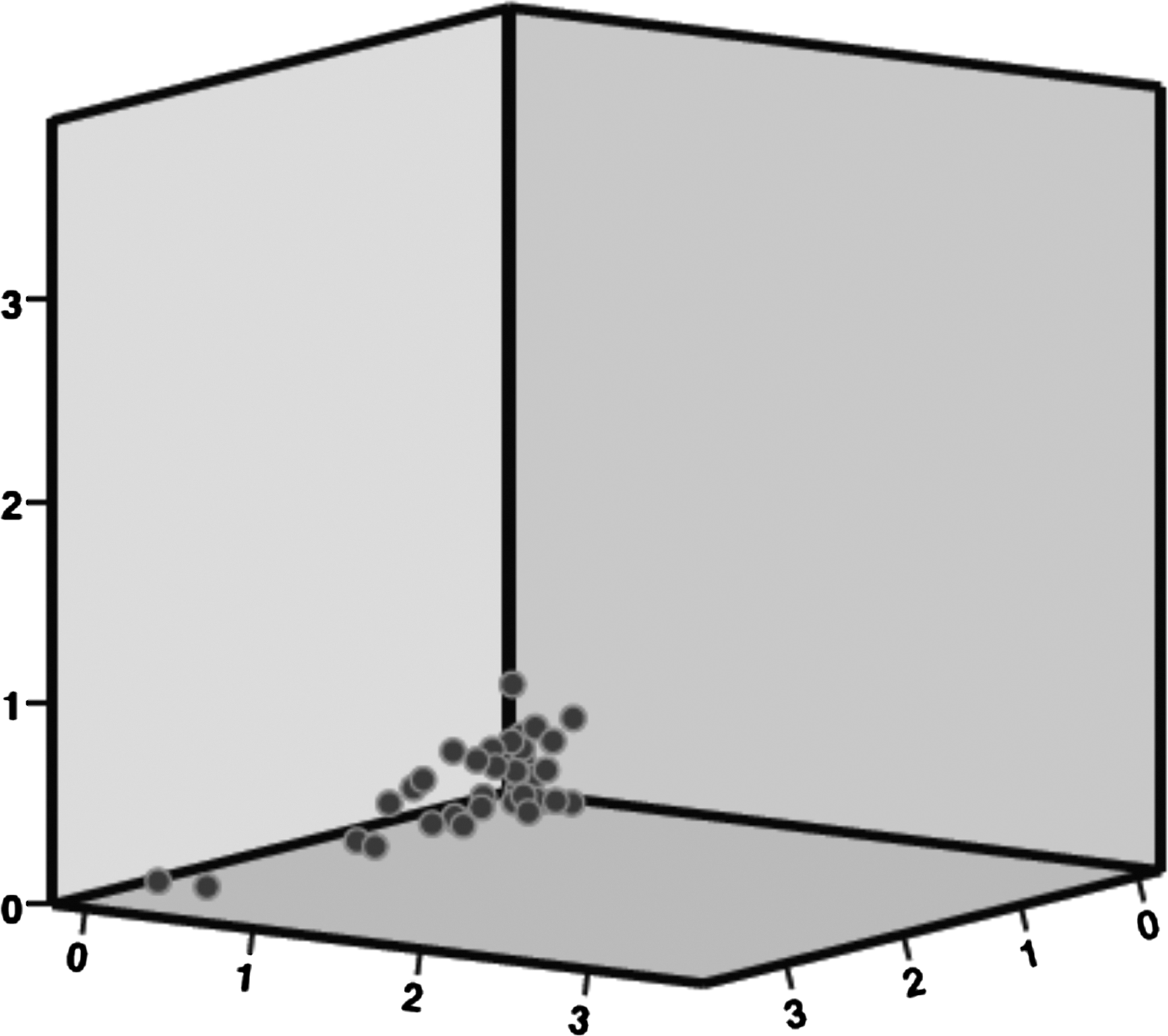
Procedural targeting error in CIRS phantoms in mm.
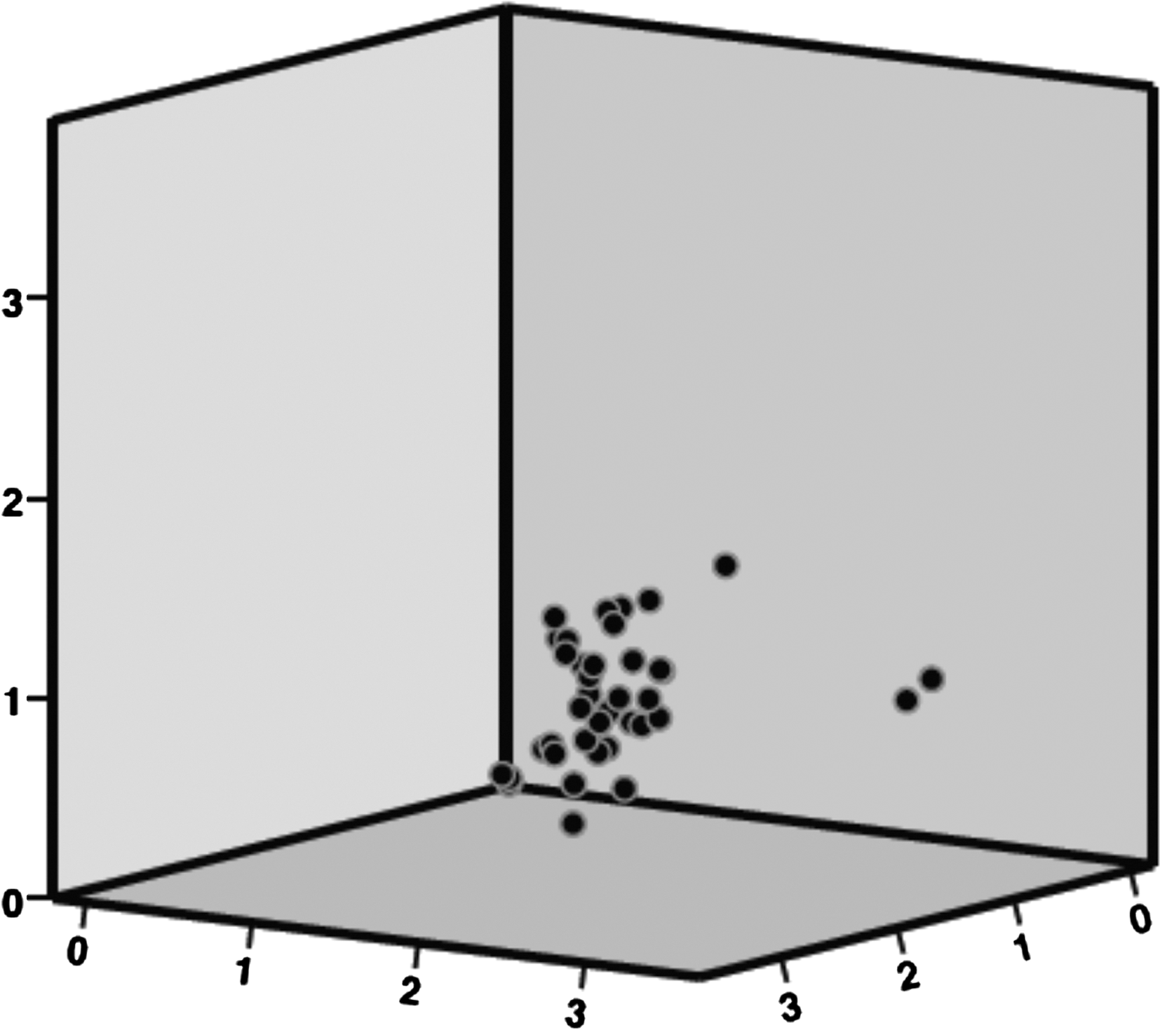
Targeting error in CIRS phantoms in mm.

Discussion
In vivo, the BiopSee system automatically calculates the procedural TE between the virtually planned biopsy trajectory and the manually registered 3D needle position of each biopsy. In this study, our aim was ex vivo validation of this error. By performing postinterventional MRI on phantoms, exact measurement of target registration errors is possible. Comparing our results (TE 0.83 mm vs PTE 0.26 mm), the software based error calculation seems appropriate for in vivo biopsies.
Ukimura and coworkers 22 recently presented data on phantom biopsies using the same CIRS 053 and CIRS 066 prostate models and elastic registration of the 3D trajectory of TRUS-guided biopsies with an external software (Koelis, France). All 27 biopsies from hypoechoic lesions were on target. In isoechoic lesions, however, only 24/27 biopsies hit the randomly placed 0.5-cc lesion within the phantoms. The authors describe a learning curve in performing biopsies using elastic fusion and report a higher accuracy in the last biopsies. The target registration error in their study was 2.9 mm. Similarly, using MRI/TRUS-fusion systems for prostate biopsies, Xu and associates 19 found an accuracy of 2.4 mm±1.2 mm in their system, while Singh and colleagues 16 reported an error of 3.3 mm.
In our study, all biopsies from both hypo- and isoechoic lesions with a volume of 0.5 cc were on target. Regarding the maximum resolution of our MRI of 0.5×0.6 mm, all biopsies were delivered with errors below 1 mm. The differences between the previous studies and our data might be explained by the perineal biopsy approach, which allows straight needle insertion and easy US monitoring of the biopsy procedure. In patients, we experienced a slightly higher PTE (1.7 mm vs 0.26 mm). 20 Similarly to biopsies in men, we observed the highest deviation between planned and registered coordinates in the sagittal plane (up to 3.22 mm). Both in vivo and in the phantoms used here, these errors are from cranial movement of the prostate. This error might be prevented by automatic segmentation of the prostate and flexible image-to-image registration, which is actually under investigation.
Continuous improvement of MRI imaging and the ability to take precise biopsies from MRI suspicious lesions questions the necessity to acquire high numbers of biopsy cores. To be able to reduce the amount of biopsies per patient, we will validate our biopsy results and MRI data with whole mounts of prostatectomy specimen. These correlative investigations are still ongoing.
Conclusions
As shown here, the system used in the current study is very precise in targeting MRI suspicious lesions. Thus, the BiopSee platform can play a significant role for simplified diagnostics and future focal treatment of low-risk prostate cancer.
Footnotes
Acknowledgments
We cordially appreciate the excellent help of the entire staff at the department of urology and the department of radiology of the German Cancer Research Center. We like to give thanks to the European Foundation of Urology for sponsoring of used phantoms.
Disclosure Statement
P. Zogal is an employee of MedCom GmbH. For the remaining authors, no competing financial interests exist.