
Abstract

Introduction
A major effort of the plant biology scientific community aims to understand and rationally modify plant cell walls in order to ease the conversion of lignocellulose into transportation fuels. 8,9 A large number of plants with modified cell wall composition are being developed. 10 These modifications are likely to have a direct effect on the overall mechanical strength and properties of the plants. 11 –15 While genetic modification of cell wall composition and the resultant three-dimensional organization of the plant cell wall may be beneficial for biomass degradation, decreased mechanical stability of plant stems may have an adverse effect on the growth of the plant and its ability to tolerate adverse environmental conditions. 16
Mechanical strength has been studied in the past to explore natural environmental conditions under which a plant could sustain growth as well as to determine the effect of genetic manipulations on the overall mechanical strength of the plants. The pulp and paper industry has also used mechanical strength as a quality control metric for the fibers produced. 17 To this effect, an in-house instrument had been developed by Prat and Paresys for measuring different mechanical strength properties of plant stems. 18 It is crucial to develop and adapt a characterization pipeline that allows the direct measurement of mechanical stability as well as ductility of the biomass, and to correlate such measurements with biomass degradation analysis. Therefore, tensile testing of plant biomass, carried out as standard American Society for Testing and Materials (ASTM) procedures for a variety of materials, is expected to yield insight into maximum mechanical strength, total strain, and the nature of the material. 19 Tools currently available for measuring the mechanical strength of plant stems require sample preparation and/or modification of the plant stem or their fibers. 20 In contrast, we have now developed a platform for swift characterization of the mechanical properties of plants with minimal sample preparation. Further, we use scanning electron microscope (SEM) imaging methods to confirm the fracture patterns of the materials as a means of validating the mechanical stress measurements.
Materials and Methods
Mechanical properties of plant stems dictate their response to various external forces. Uniaxial tensile testing—in which the force required to induce a uniaxial change in deformation is measured—can be used to estimate mechanical properties such as ultimate stress, ultimate strain, elasticity, and Young's modulus. The samples are either bolted or clamped to the instrument before the application of stress. Due to the delicate nature of the plant stems, commercially available mechanical strength instruments are not usable. A mechanical strength instrument and a sample handling procedure specifically designed to measure the mechanical properties of plants were developed.
Sample Handling
The stems or the leaves of the plant were cut to a length of ∼50 mm before the analysis and immersed in water until the analysis to prevent the collapse of intracellular structure of the stem due to dehydration. 18 Cross-sectional area of the plant stems has been previously measured by using the mean diameter of the stem. 11 The thickness of the plant samples was measured using Vernier caliper. The plant stems consist of void volumes usually used for the transport of minerals, nutrients, etc. The void volume does not contribute to the overall strength of the material, and these volumes were not included in the calculation of cross-sectional area for the samples. The samples presented in the following work were not freeze-thawed before the analysis.
Mechanical Stress Measurements
We designed and constructed a mechanical stress analyzer consisting of a stepper motor to apply the tensile force, as well as a force sensor to find the tensile force applied by the motor (Supplementary Fig. S1a; Supplementary data are available online at
Stepper motor
The stepper motor (IMC17-S04-A) was purchased from RMS Motion (Carson City, NV); a step size of the motor can be varied from 1 mm/s to 0.01 mm/s. A micrometer screw was attached between the stepper motor and the sample holder (Fig. S1b) to ensure that the speed of the step motor corresponded to the specified rate of elongation. The step size of the stepper motor was calibrated every day using the micrometer screw gauge. By recording the number of revolutions the stepper motor takes when the micrometer screw revolves by 5 mm, a conversion factor was calculated and used to adjust the speed of the motor. The speed of the stepper motor was used to determine the rate of elongation of the plant stems. The total elongation of a plant stem was calculated as the product of time of the experiment and the rate of elongation.
Force sensor
The force sensor, consisting of the load cell (UF1 Low Range Isometric Force Sensor) and the analog output/controller for the force sensor (ADW 15) was purchased from LCM Systems (Exeter, Devon, UK) (Fig. S1b). The force sensor can measure a maximum force of 1,500 gmf (∼14.7 N). The force sensor was calibrated every month according to the procedure described by the manufacturer. The force sensor was precalibrated with known quantities of water from 0 to 1,500 gmf; 0, 250, 500, 750, 1,000 and 1,500 gmf were used as calibration points. Further, rectangular strips of Whatman glass microfiber filters were subjected to tensile tests, and the resulting stress and strain values had a standard deviation of less than 5%. In the case of plant stems, the force recorded by the instrument was divided by the cross-sectional area of the plant stem to find the stress being applied.
Sample holder
The sample holder consists of a three-plate system to hold the plant stem. The three plates are held together by a three-screw system (Figure 1a). The middle plate in all the sample holders was 5 mm in width. The plates at the end consist of two screws each, which are used in binding the sample holder plates to the system. The plant stems were glued on to the sample holders using hot glue, and the plate in the middle provided support to the stem (Figure 1b). The middle plate was removed after mounting the sample holders (with plant stems) on the instrument (Fig. 1c-e). The glue was applied until the end of the holder plates, so as to maintain a constant length (5 mm) for the segment being tested. Through this procedure, only 5 mm of the stem was suspended for analysis. The strain at the end of the experiment was calculated as the ratio of elongation to the initial length of the stem (5 mm). The measurements for which the plant stem broke at least 1 mm away from the glue were considered for further analysis. We could thus avoid errors in stress measurements resulting from clamping/gluing of the stems.

Stem holder used for holding the plant stem. Plant stem before
Instrument control and data acquisition
The RS232 ports of force sensor and the stepper motor allowed digital control of the instrument. A graphical user interface was developed using VisualLink software (Mantracourt Electronics Ltd, Exeter, Devon, UK) for instrument control and data acquisition (Fig. S1c). It allowed for various modes of tensile testing and compression testing procedures. The data were acquired every 0.03 s during an experiment. The calibration of both the force sensor and stepper motor was also conducted digitally. The software converts the force to stress (ratio of force and cross-sectional area) and the elongation to strain (ratio of elongation to the initial length). It also enables the real-time plot of the stress strain curves. The data were recorded in .dat format and could be easily imported to data analysis tools such as Microsoft Excel.
Data analysis
Tensile stress is calculated as a ratio of force to the cross-sectional area. In ductile materials, as the cross-sectional area changes due to deformation under tensile stress, the measurement of tensile stress using the above method gives only an approximate value for stress. Since brittle materials undergo little or no deformation during tensile testing, the above method provides a more accurate estimate for the stress encountered by the materials. The change in cross-sectional area for the plant samples during the analysis was assumed to be minimal for the purpose of this study. There was no measurable difference between the stem cross-sectional areas before and after application of stress (Fig. S2). The nominal stress was calculated based on the cross-sectional area of the sample before tensile tests. The total strain that a material underwent during tensile testing can be calculated as the ratio of the total change in length of the material to the initial length of the material. The relative nature of the samples (brittle or ductile) can be inferred from the comparison of total strain they undergo during tensile testing. A brittle material undergoes little deformation and shows a lower amount of strain when compared to ductile materials, which undergo a higher deformation and hence show higher amounts of strain. The breaking strength of material, defined as the mechanical stress at the breaking point, is another important property. The maximum mechanical strength and the breaking strength of a material need not be the same. During tensile testing a material elongates and reaches a maximum stress value—this is the maximum force the material can endure. The material may not break at this point, but on further increasing the strain, the material becomes weaker and breaks at a force lower than the maximum strength. In the case of plant samples analyzed in this work there was no difference between maximum strength and the ultimate stress (or the stress at breaking point).
Results and Discussion
Brittle Culm-Rice Mutant
To validate our method, we compared wild type rice with a brittle culm (bc) mutant. Several bc mutants have been reported in rice, characterized by brittleness, dwarfing, and withering of the leaf apex. 21 These mutants display reduced mechanical strength and have been instrumental in studying the development and formation of secondary cell walls in the grasses, including rice. 22,23 Three distinct brittle mutants of rice carrying Tos17 transposon insertional mutants correspond to cellulose synthase (CESA) encoding genes OsCesA4, OsCesA7, and OsCesA9. 23 All three null mutants exhibited dwarfed growth habit, easy fracturing of leaf and culm by stressing between fingers, and thinner walls in cortical fiber cells due to dramatic reduction of cellulose content in the secondary cell walls. 23 In this study, we used an Ac/Ds-tagged mutant (RGT3584) in an exon of one of these genes, OsCesA7, which exhibited the bc phenotype, and compared its mechanical strength with wild type rice plants. All plants were grown under greenhouse (Department of Plant Pathology, University of California, Davis) conditions (8–16 h day/night cycle; >80% relative humidity (RH); 20–35°C) and subjected to tensile stress at heading stage to assess their mechanical strength. The cross-sectional area of the leaves was calculated as the product of the thickness and width of the leaf. The tensile stress was applied at a constant rate of 0.1 mm/s. As expected, the leaf blades of the bc mutants underwent a brittle fracture (lower strain) when compared to the leaf blades of the wild type, which underwent a ductile fracture (higher strain) (Fig. 2a). The stress versus strain curves of Y-leaves (the most recently fully expanded leaf of the rice plant) from different wild type plants agreed well for the most part, which demonstrates the reproducibility of the mechanical stress assay (Fig. 2b), although some variability in the breaking end-point was detected. As shown in Table 1, we found that the flag leaf blade (the top most leaf below the panicle) of rice plants displays a higher mechanical strength than other leaf blades of the plant. The portions of the leaf blade closer to the tip were weaker than the portions closer to the culm (Table 1). We found that the leaf blades of the wild type had a higher mechanical strength than the leaf blades of the bc mutant, with flag leaf blades displaying the most prominent difference. As shown in Table 1, the variability within the same leaf was higher than the variability between similar parts of different leaves. We performed SEM imaging of the fractured ends to examine the exact type of fracture and to visualize the change in microstructure before and after exposure to stress. SEM images of the wild type showed the fibrous extensions to be in agreement with the higher ductility of the wild type plant leaf blade (Figs. 3a-c , SF1), whereas the bc mutant leaf blade shows a sharp fracture boundary, with no fibrous material visible, hence supporting the brittle nature of bc mutants (Figs. 3d-f , SF3).
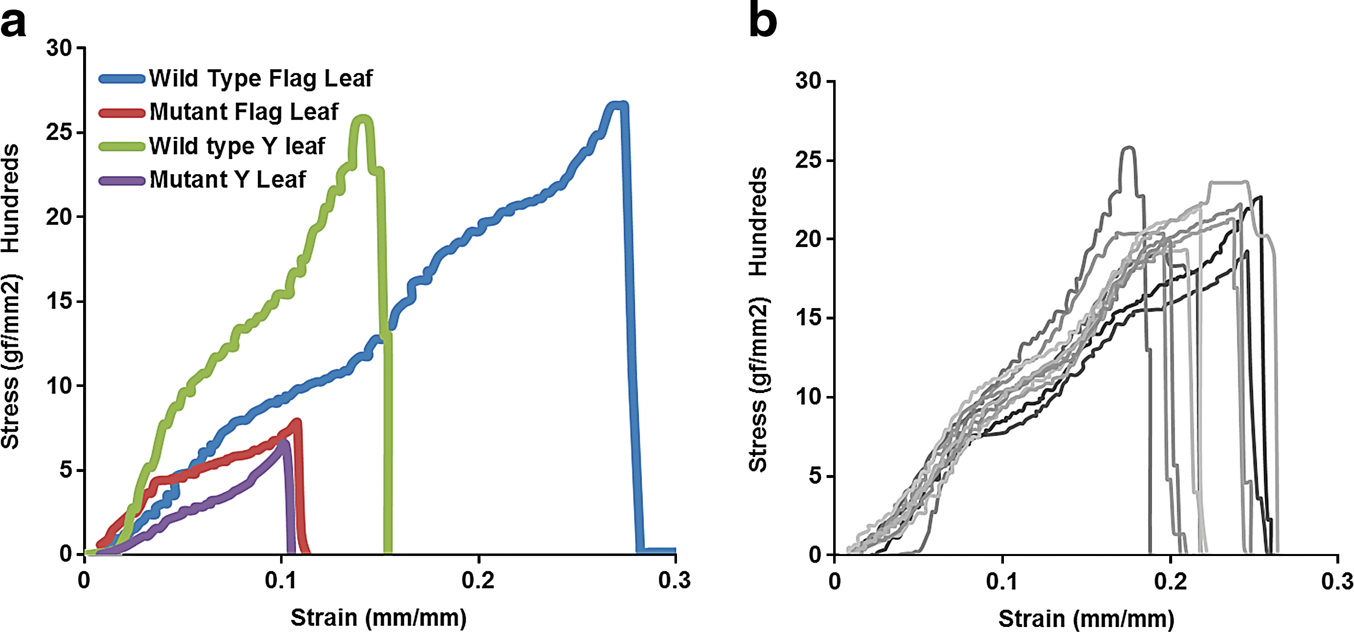
Stress vs. strain curves. Representative stress vs. strain curves for Y-leaves and flag leaves of wild type plants show higher ultimate stress and strain than those of brittle culm mutant: parts corresponding to the middle of the leaf

Fracture patterns of the leaves. SEM images of the fractured flag leaf of wild type, showing fibrous fracture (
Ultimate Stress and Strain of Different Leaf Blades (Averaged Over the Same Leaf) and Different Parts of the Same Leaf Blade (Averaged Over Different Leaves)
Tip of the leaf blade; bmiddle of the leaf blade; cportion of the leaf blade near the culm; dforce greater than the measurable range of the instrument.
Arabidopsis Wild Type Grown Under Different Light Conditions
To address the sensitivity of our mechanical characterization pipeline, we tested Arabidopsis wild type plant stems that were grown under different light conditions, which are expected to affect secondary cell wall development and, therefore, mechanical strength. Arabidopsis plants used for stress analysis were initially grown in short day (SD: 10 h/14 h-day/night cycle of light daily at 22°C in growth chamber) before being moved to long day (LD: 14 h/10h-day/night cycle of light daily at 20–23°C in growth room), and a different set of wild type plants were grown exclusively in the LD setting. Plants grown under SD/LD had higher stem diameter and showed higher recalcitrance to saccharification when compared to plants grown under LD (Fig. 4a). Differences in biomass composition can also be measured by thermogravimetric analysis (TGA). 24 From TGA of the plant stems, we observed that the untreated LD plants decomposed at a lower temperature than the SD/LD plants, showing easier thermal breakdown of the LD plants. Ionic liquid (IL) pretreatment was conducted to assess more fully the recalcitrance and digestibility of these plants after pretreatment. Based on the thermogravimetric curves of the pretreated samples, we infer that after IL pretreatment the cellulose in SD/LD plants is converted into an amorphous form, while in LD plants it transforms into cellulose II (Fig. S4). It has been shown previously that the ratio of cellulose II to amorphous cellulose formed after IL pretreatment increases with decreases in recalcitrance of the biomass. 25 From these results, we infer that the SD/LD Arabidopsis is more resistant to pretreatment and hydrolysis than LD Arabidopsis (Fig. 4a).
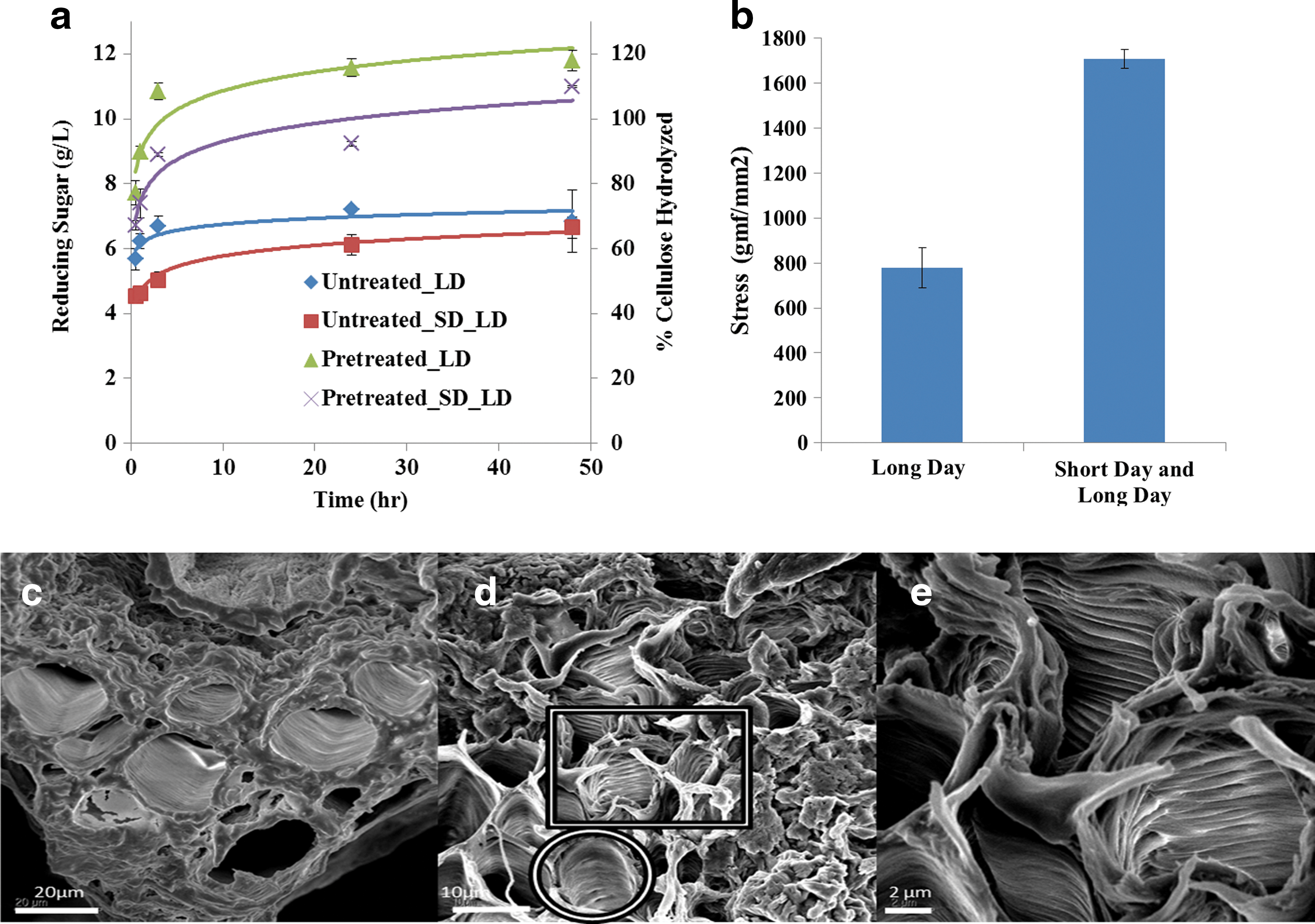
Effect of growth conditions of Arabidopsis plants. Enzymatic hydrolysis of untreated and pretreated Arabidopsis plants shows higher recalcitrance for plants grown SD and LD when compared to those grown only in LD
The tensile stress was applied on LD and SD/LD Arabidopsis plants that were 6 weeks old at a constant strain rate of 0.05 mm/s. The wild type grown in short days and then moved to long days showed higher mechanical strength than the wild-type plants grown only in long days (Fig. 4b). SEM analysis of plant stems that were not subjected to mechanical stress showed intact microfibrils that were very closely packed (Fig. 4c). After subjecting the plants to mechanical stress there was a change in the microstructure of the plant stems. These tissues appear elongated (e.g,. in the area depicted by a square) when compared to other tissues (area depicted by a circle) (Fig. 4d). We observed gaps between each layer of some tissues and small fractures in some tissues at the fracture point (Fig. 4e). The fact that we can find the differences in the mechanical properties of wild type samples grown under different light conditions suggests that our approach is very sensitive to changes in the environment and in the growth condition, likely to affect cell wall organization.
Conclusions
The secondary cell wall plays a major role in the mechanical strength of the plant. Mechanical strength assays can be successfully used to measure quantitatively the tensile strength of plant stems. We compared a brittle rice mutant in a cellulose synthase-encoding gene with the wild type plant. Lower mechanical strength with a brittle fracture of the leaf blades was observed for the mutant by tensile tests and SEM. We also observed that Arabidopsis plants grown under short days have higher strength and show higher recalcitrance to saccharification before and after IL pretreatment. We observed that only some tissues exhibited a change in the microstructure and helped maintain the ductility of the plant stem. The knowledge gained from this present study can be utilized to study candidate bioenergy crops and indicates that an assay based on mechanical strength measurements can be used to characterize genetic modifications in the plant cell wall. Together, mechanical testing and SEM analysis of the fracture surface yield quantitative insights into mechanical strength and elasticity of the samples and provide visual feedback on the types of cells that are predominantly responsible for ductile behavior.
Footnotes
Acknowledgments
This work was part of the Department of Energy Joint BioEnergy Institute (
Author Disclosure Statement
No competing financial interests exist.
References
Supplementary Material
Please find the following supplemental material available below.
For Open Access articles published under a Creative Commons License, all supplemental material carries the same license as the article it is associated with.
For non-Open Access articles published, all supplemental material carries a non-exclusive license, and permission requests for re-use of supplemental material or any part of supplemental material shall be sent directly to the copyright owner as specified in the copyright notice associated with the article.