
Abstract
This paper presents a promising potential scale-up method for cell-free protein production that integrates microfluidic devices and DNA-based hydrogels (P-gels). The microfluidic devices were fabricated using established photolithography techniques. The P-gels were formed via enzymatic ligation of branched DNA nanostructures with genes. More specifically, the microfluidic devices contained droplet-forming junctions through which numerous micron-sized P-gel droplets were produced. The advantages of our microfluidic-based approach include highly controlled fluid manipulation, rapid droplet generation, high reproducibility, and low sample consumption. P-gel droplets successfully expressed green fluorescent protein (GFP) in high yield, and the microfluidic devices achieved a variety of P-gel droplet sizes while maintaining uniform morphology and a high generation rate. We envision that our system could provide a cell-free platform for both high-throughput and scale-up production of multiple proteins.
Introduction
We have developed a cell-free, protein expression system based on a DNA hydrogel (P-gel). P-gel consists of X-shaped DNA covalently ligated to genes and its use can increase the yield of cell-free SPS systems. 5,6 The P-gel format has several advantages, including 3 times longer duration of expression than that of SPS, a 73-fold faster expression rate than that of SPS in the first 12 hours, and reusability. 6 To adapt the P-gel system for industrial applications, we incorporated a microfluidic technology that reduces overall cost by minimizing reagent consumption and reaction time with controls at nano- to femtoliter-scale precision. 7 –11 In addition, our microfluidic devices can generate, in a high-throughput manner, a large number of P-gel droplets from which efficient protein expression on a larger scale can be realized.
Materials and Methods
Microfluidic Device Fabrication
CAD design, mask pattern generation, and mold fabrication
Conventional photolithography processes were employed to fabricate a mold from which thousands of microfluidic device replicas can be made. 12,13 The design, created using the computer-aided design (CAD) software program AutoCAD (Autodesk, San Rafael, CA), is shown in Fig. 1A. This design was then transferred to a chrome-glass mask, in which the pattern was etched out, resulting in a mirror-image of the microfluidic device design. Contact-mode photolithography was used to create the master mold for casting microfluidic device replicas (Fig. 1B). A 4-inch silicon (Si) wafer was first spin-coated with a 40 μm-layer of a negative photoresist (SU-8; MicroChem, Newton, MA). After a 3-minute prebake at 90°C, the pair was placed under the mask and exposed to UV light (365 nm) for 40 seconds in a vacuum using a Mask Aligner (ABM, Scotts Valley, CA). After post-baking at 95°C for 5 minutes, the Si wafer was developed for 3 minutes, resulting in a negative copy mold of the device on the Si wafer.
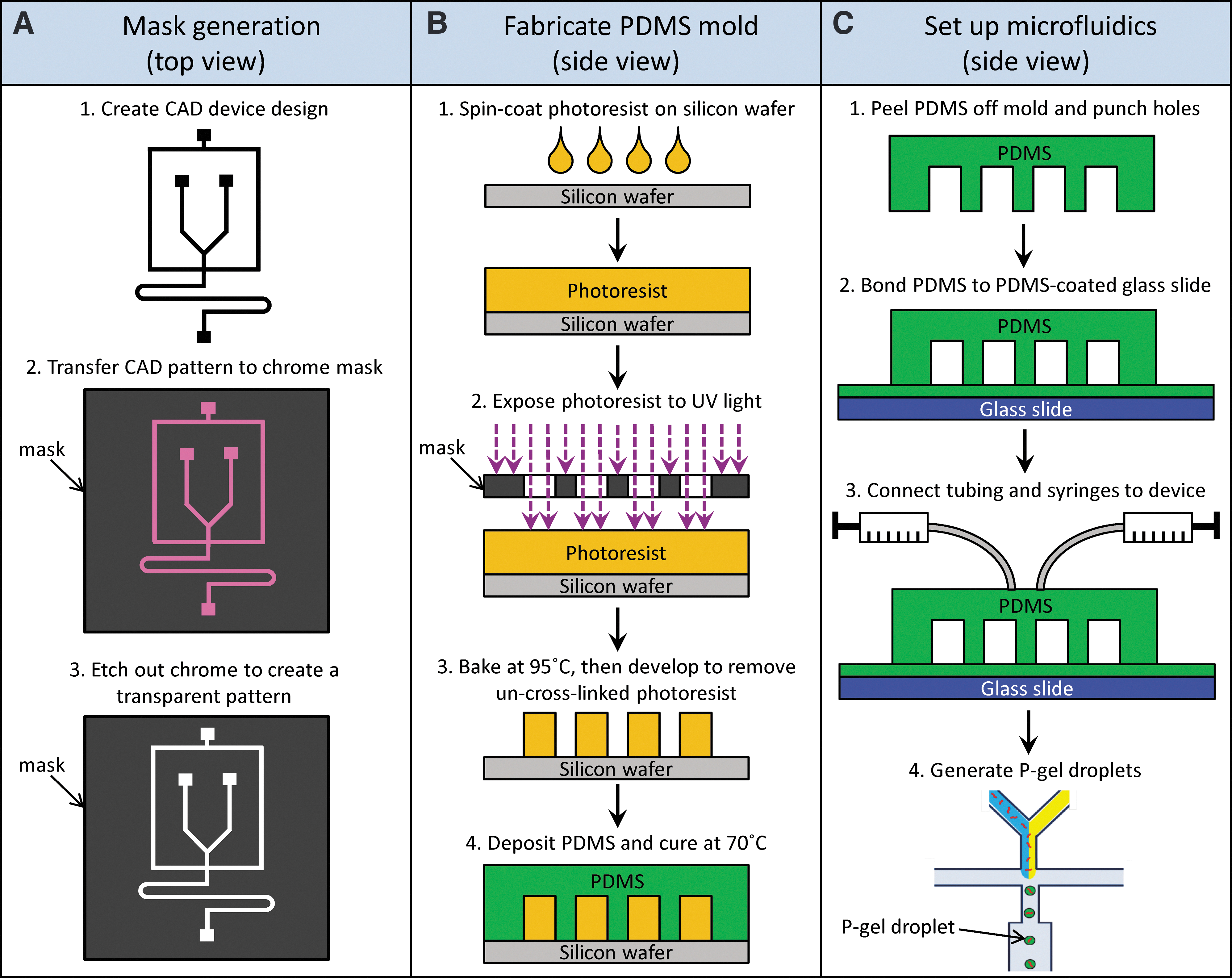
Fabrication procedure for the polydimethylsiloxane (PDMS) microfluidic device. The device design is created in a computer-aided design (CAD) software and transferred and etched onto a chrome mask
PDMS cast replica
The master mold was used for generating polydimethylsiloxane (PDMS) microfluidic devices (Fig.1B-C). 12,14 The Si wafer was first plasma oxidized and coated with (perfluorooctyl) trichlorosilane (FOTS) using a molecular vapor deposition system. FOTS provided an anti-stiction layer that allowed the wafer mold to be reused thousands of times. The PDMS was then poured onto the mold and baked at 70°C for 1.5 hours.
Device assembly
Vertical inlet and outlet holes were punched out of the PDMS prior to assembly (Fig. 1C). The assembly was then sealed onto a glass slide to close the channels of the device. The sealed device was cured overnight in a dry chamber to ensure permanent bonding.
X-DNA and P-gel
The X-DNA was custom-designed and synthesized by annealing four ssDNAs, according to our previously published results (Fig. 2). 5,6,15 P-gel was formed by cutting the plasmid containing a green fluorescent protein (GFP) inserted with Aat II and then ligating the plasmid to X-DNA branches at a 1:2000 molar ratio.
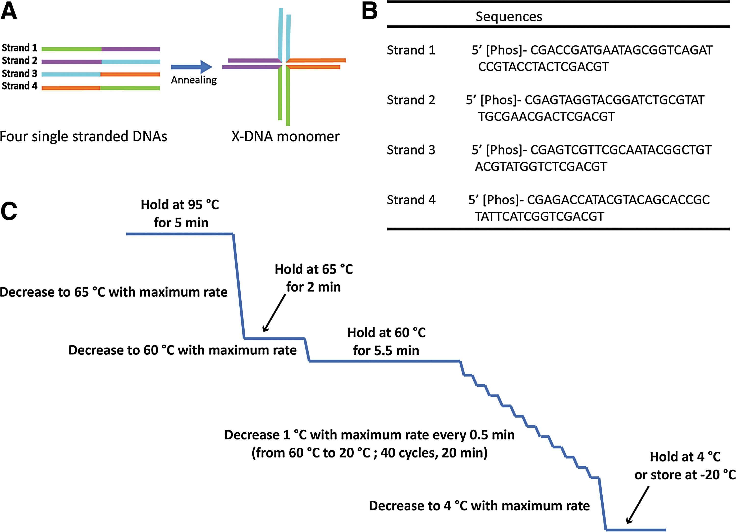
Four single-stranded DNA (ssDNA) molecules anneal to form an X-DNA monomer. Custom-designed ssDNA sequences used to form P-gel X-DNA
Microfluidic Generation of DNA Hydrogel Droplets
Setup
The reagents were separated into two glass gas-tight syringes, one containing X-DNA and the GFP gene and the other T4 DNA ligase and 1x ligase buffer. To form the droplets, mineral oil was used with 4% surfactant (ABIL EM 90, Evonik Industries, Essen, Germany). Details of the droplet-forming procedures are illustrated in Fig. 3.
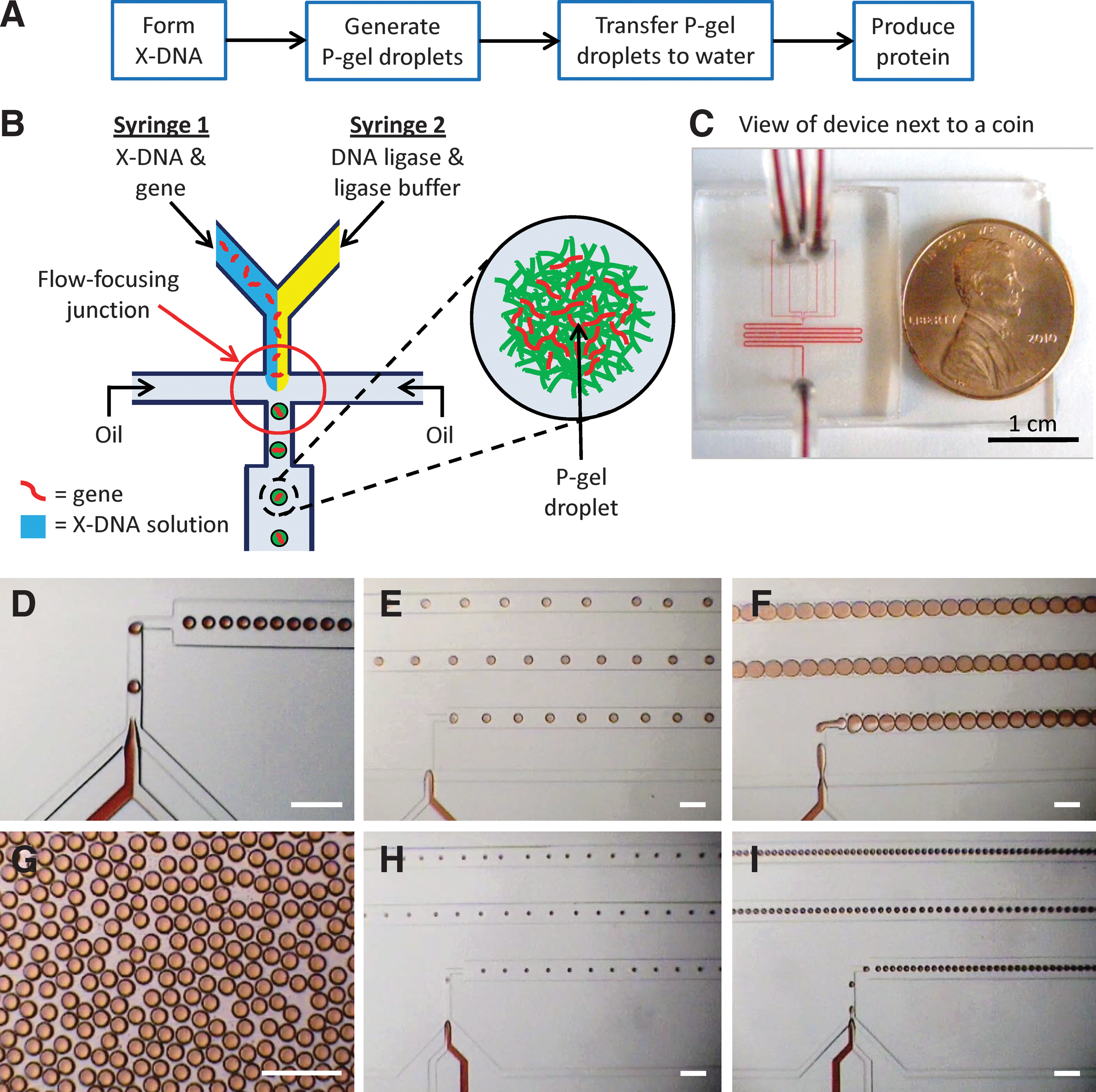
P-gel droplet formation procedure and device images demonstrating the versatility and high-throughput capacity of microfluidic design. Flow chart showing the main steps for a P-gel droplet protein expression test
Flow-focusing junction for precise droplet formation
The microfluidic device contained a flow-focusing (FF) junction that combined two immiscible liquids (oil and aqueous fluid). The oil separates the stream of aqueous liquid into uniform microspheres by pinching off incoming aqueous (DNA and ligase) solution into a stream of droplets (Fig. 3B). 12,13 Ligation began as soon as the T4 ligase was mixed with the X-DNA and genes. After P-gel droplets were pinched off by oil, the channel widened to form a serpentine mixing channel. Fresh P-gel droplets were then collected from the device outlet and incubated overnight at 16°C to allow ligation to complete before transferring to nuclease-free water.
Characterization of P-Gel Droplets
Cryo-SEM and SEM imaging
A SEM equipped with a cryostage was utilized to observe the surface structure of P-gel droplets (Hitachi High-Technologies; Tokyo). The P-gel droplets were frozen rapidly in liquid nitrogen before loading onto a pre-cooled cryo-SEM stage at −150°C. The samples were then warmed from −150°C to −90°C for 15 min to eliminate existing crystalline water. P-gel droplets were subsequently transferred to a preparation stage for coating with an argon ion beam (30 sec) and reloaded to the SEM chamber. The surface morphology of the P-gel droplets was examined at a voltage of 3 kV in low vacuum mode utilizing a Hitachi 4500 SEM (Hitachi High-Technologies, Tokyo) (Fig. 4A-B). For field-emission SEM (FESEM), P-gel droplets were first frozen rapidly in liquid nitrogen and freeze-dried in a lyophilizor at −42°C under vacuum overnight until all water was completely sublimed. The morphology of dry P-gel droplets was observed by FESEM (Fig. 4C-D).
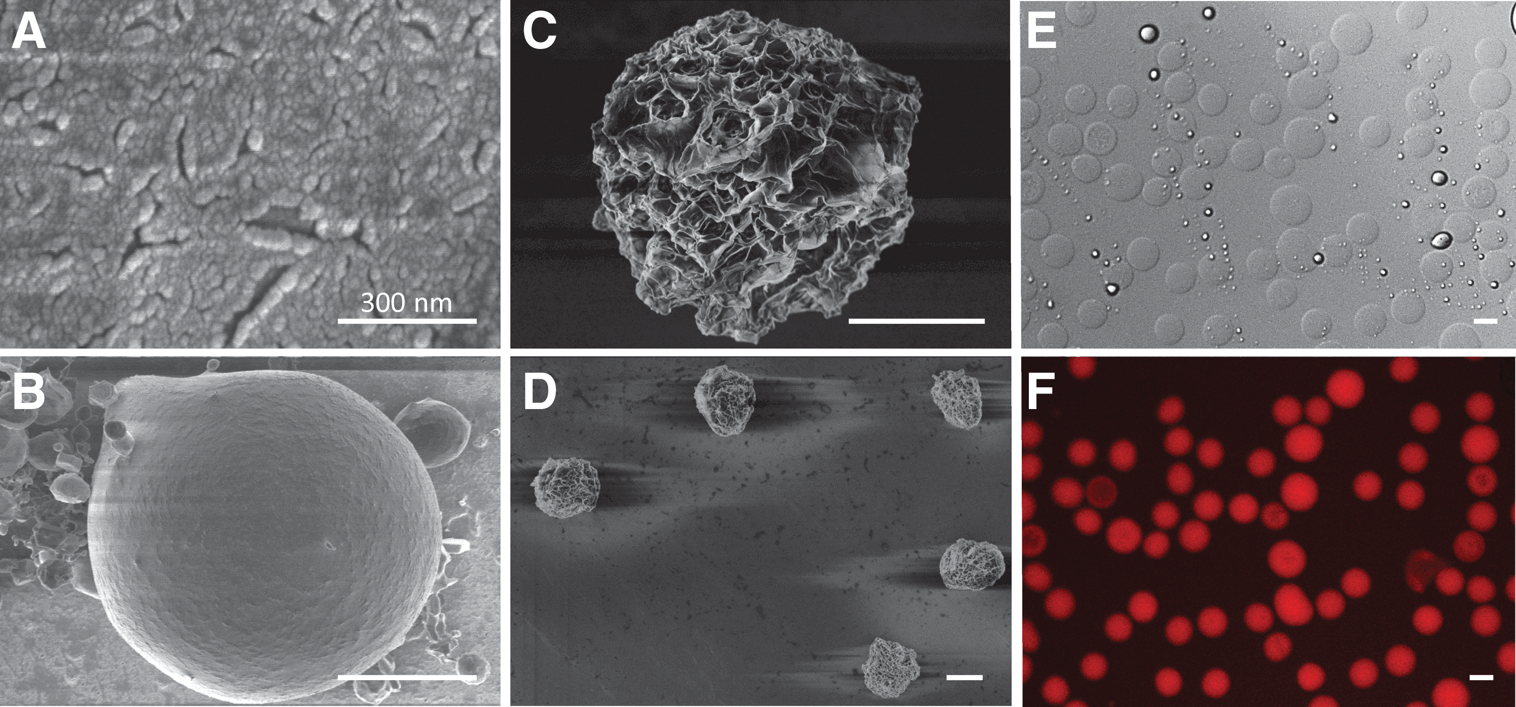
Microscope characterization of P-gel droplets. Cryo-SEM image of a region of the P-gel droplet surface
Cell-Free Protein Production
Cell-free protein expression
We successfully tested different commercial cell-free lysates with the P-gel system, including those from E. coli and wheat germ (5 PRIME, Gaithersburg, MD). 5,6 P-gel droplets were mixed with 24-μL lysate and incubated at room temperature with no shaking. GFP was used as a model protein and its expression was tracked using epi-fluorescence microscopy. In addition, a microplate fluorometer was employed to quantify the GFP yield.
Results and Discussion
Generation of P-Gel Droplets for Protein Production
This system rapidly generated P-gel droplets containing a specific gene or genes. We first stained X-DNA for visualization of the FF junction and to confirm the high monodispersity of droplets (Fig. 3D-G). In addition, we varied channel widths to demonstrate that droplet size and generation rate were tuned by altering the device design (Fig. 3E-I). We observed that the surface of the P-gel droplets was porous (Fig. 4A-B) while the inside attained a porous network morphology (Fig. 4C-D). Furthermore, droplet production was confirmed by both fluorescence and bright field images (Fig. 4E-F). At each flow rate ratio (i.e., aqueous vs. oil flow rate), the size distribution of the droplets was narrow (Fig. 5A); by altering the channel width (35 μm vs. 60 μm), a range of P-gel droplet sizes was consistently achieved (Fig. 5B).
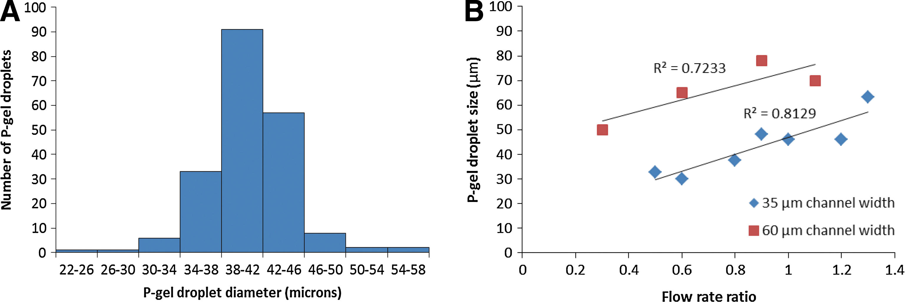
Characterization data for P-gel droplet size distribution and the relationship between droplet size and device channel width and flow rate ratio. Histogram of P-gel droplet size distributions
Advantages of Integrating Microfluidics with P-Gel for Scale-Up Protein Production
In bulk, P-gel achieved a much higher protein yield than conventional SPS. 6 Converting from bulk P-gel (10–300 μL volumes) to micron-sized P-gel droplets (1–100 picoliter volumes) resulted in a similar yield while at the same time provided a versatile format ideal for scale-up production. In particular, our device can generate droplets as rapidly as 104 per second (close to one billion per day), and large numbers of droplets can be generated automatically and continuously. 16 Furthermore, P-gel droplets can be easily customized for different designs by methods such as varying gene amounts and droplet sizes.
P-Gel Droplet Protein Expression
We compared GFP expression in P-gel droplets to that of SPS to evaluate the protein production yield (Fig. 6). Even under non-shaking conditions, P-gel droplets had a similar GFP production trend as SPS when total amount of gene, total reaction volume, and temperature were kept constant. Our results demonstrate that P-gel droplets are robust and efficient, providing a practical alternative format for protein expression. P-gel droplets have greater scale-up potential since they can be continually generated using automated microfluidics. P-gel droplets can also be separated out of a reaction system and re-used for additional protein expressions. In addition, we have previously shown that P-gel can continuously produce proteins for more than 36 hours, while SPS protein production typically plateaus after 12 hours. 6
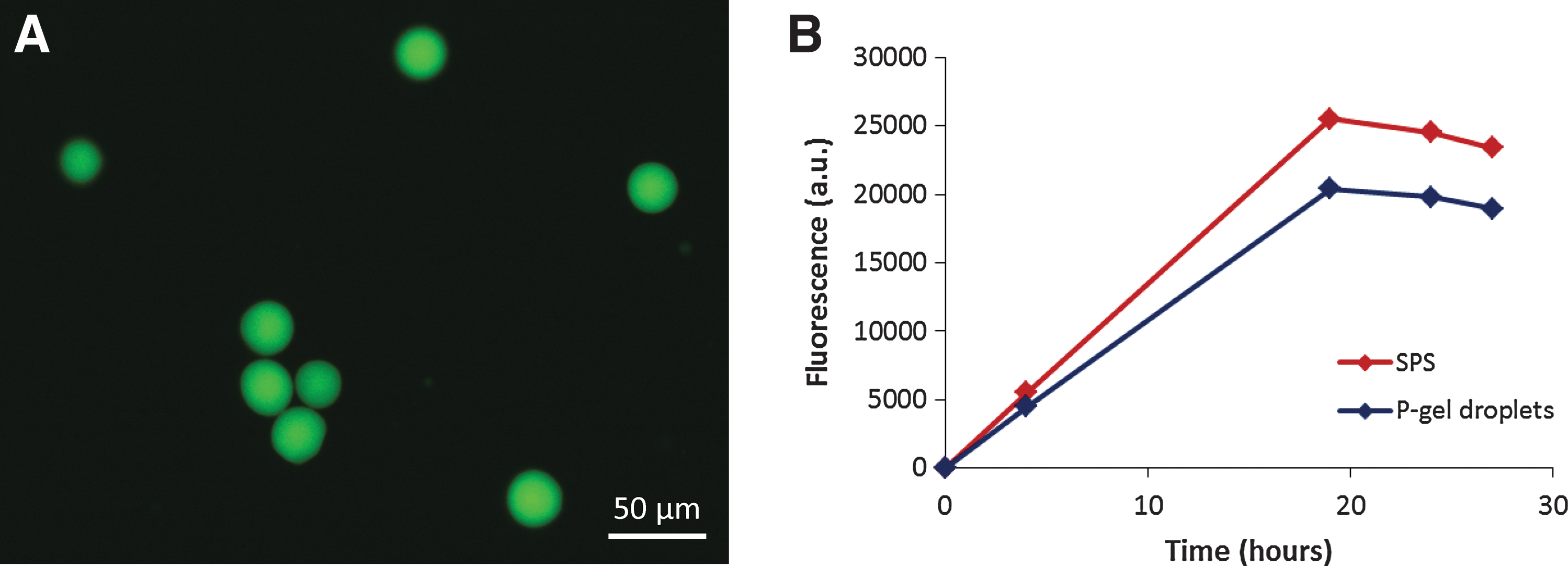
Evidence of successful protein expression inside P-gel droplets. Green fluorescence image of P-gel droplets expressing green fluorescent protein (GFP)
Cost Analyses
The microfluidic device is extremely small, no larger than a penny (Fig. 3C), and consumes very little reagent. In addition, due to the small size, microfluidic devices can be easily connected in a massively parallel fashion for high-throughput production of the same or even different proteins. Although the initial photolithography fabrication process for making a mask and a Si-mold can be expensive, once the mold is made it can be reused thousands of times. The cost per device, everything included, is thus very minimal—approximately $1.75 per device. Lysate costs can be dramatically reduced because of the extremely small volumes, and reduced further by preparing them in the laboratory. 17 External compressed air instead of syringe pumps will be more cost-effective in a scale-up scenario. 18 Overall, the cost reduction that can be achieved with microfluidic-based P-gel droplets is significant, particularly in scale-up settings, because expensive equipment such as fermentors, heaters, and shakers, are eliminated and reagent consumption and daily quality controls—such as concerns over contamination and mutations—are reduced.
Conclusions
Initially developed for fabricating electronic microchips in the semiconductor field, nanofabrication and photolithography in particular can find broad applications in biotechnology. We have demonstrated that cell-free protein expression can be realized from a hydrogel format, and more recently, from a droplet hydrogel format as well. The key technical component is the use of microfluidic devices. Our microfluidic-device-based P-gel droplet is a platform technology with promising potential for both high-throughput and scale-up protein production. In addition, the customizability of P-gel droplets, in combination with the high-precision fluid control through microfluidics, has enabled protein complex production within single droplets. Furthermore, we have found that P-gel droplets can be stored for months at −80°C without losing protein expression potency. Taken together, we envision that the microfluidic-based P-gel droplet system will become a robust alternative to traditional, cell-based systems. We further envision that the P-gel system in general will have a significant impact on protein production in both the laboratory and industry settings.
Footnotes
Author Disclosure Statement
DL is one of the co-founders for a start-up company, DNANO, Inc., which has licensed some of the technologies from Cornell University.