
Abstract
Forest biomass is an attractive alternative resource to fossil ones, renewable and without environmental impacts as long as forest residues are considered. Collecting and transforming forestry residues into value-added products is a challenge as they are usually scattered over a large area. To reduce the economic and environmental cost of forestry residues transformation, in-situ energy densification is a powerful solution. To achieve efficient energy densification of forestry residues and transformation for industrial use, a new pyrolysis unit designed by the University of Western Ontario is used to produce low water content pyrolysis oil and high-quality biochar. Bio-oil with 8 %wt water content is produced. Energy density of the bio-oil is compared to other densification methods, showing the interest of pyrolysis to increase the energy density of biomass. High quality and free of sand biochar is also produced. Various properties of the bio-oil and biochar are explored to determine its potential for various industrial applications in the scope of a major biorefinery project in La Tuque, Québec.
Introduction
Forest biomass is an attractive alternative resource to fossil feedstocks, being renewable and without environmental impacts, as long as forest residues are considered. 1 -3 To successfully convert forestry biomass into drop-in, quality fuels, several technology pathways exist. 4 All of them require significant biomass quantities to be economically viable. In Québec (Canada), such quantities exist, with 1.2 million Green Metric Tons (GMT) per year available for the Mauricie region alone. 5 However, these residues are scattered. Therefore, their collection and transformation raise technical and economic challenges—long-distance transportation being one of the higher costs.
One possibility to reduce these transportation costs is to perform on-site energy densification. Doing so enables the transport of a densified product instead of tree tops and branches back to a biorefinery. 6 -9 Pyrolysis is perceived as a promising candidate with various technologies under development in the lab and being scaled up. This process yields charcoal and volatile matter. The latter consists of condensable vapors called bio-oil (also known as pyrolysis oil or biocrude) at room temperatures and non-condensable (permanent) gases called syngas (i.e., carbon monoxide, hydrogen, methane). 10 Another complementary approach to balance the costs is to find high added-value applications for the bio-oil. 10 Both approaches can be combined.
Bio-oil, which is a mixture of oxygenated hydrocarbons with a high amount of water (∼25%wt), is the most interesting pyrolysis product. This liquefied biomass is more easily pumped, stored, and fed to useful processes, and is more compatible to chemical modification. 10 The main applications for bio-oil are currently for direct energy uses, co-refining, or for upgrading towards diesel or other types of ready-to-use fuels. 11,12 However, other applications can be of interest, such as bitumen and asphalt, that are gaining in popularity mostly due to a higher demand and market evolution. 13 -19
For both strategies, one of the main challenges faced by the pyrolysis oil option is its high water and acidity contents. 20 -22 The unit also needs to be compact and mobile enough to be operated close to the harvesting areas and to follow them as they change each year, minimizing transportation of raw residues.
To tackle this, researchers at the University of Western Ontario have developed a technology called Mechanically Fluidized Reactor (MFR). 23,24 Lab-scale tests have shown very low water content in the pyrolysis oil, under 1%wt. Such results are highly interesting, but need to be validated at pilot scale. An upscaled version of the MFR system has therefore been built, called the JUMBO MFR.
The JUMBO MFR is nested in the so-called intermediate pyrolysis category, in the middle range between slow pyrolysis and fast or flash pyrolysis. Slow pyrolysis provides very low bio-oil yield and is therefore more centered on the production of biochar, whereas flash pyrolysis leads to high bio-oil yield and very low biochar yield, which is usually directly burned for energy efficiency of the system. Flash pyrolysis is harder to implement in practice because significant heat transfer is required, resulting in higher costs. Intermediate pyrolysis offers a nice mixed offer that allows significant production of both biochar and bio-oil while, being technically more feasible. 25
In Québec, AE Energie Côte nord uses a fast pyrolysis technology proposed by ENSYN to produces pyrolysis oil from wood for energy application whereas Abritech sells pyrolysis solution for medium scale projects and offer a more intermediate technology developed by Dr Peter Fransham whom work follow a similar path to what is undergone in this study. 26,27
In this work, the JUMBO MFR is used to produce a heavy fraction of pyrolysis oil. The bio-oil is analyzed and treated to reach suitable characteristics for asphalt and bitumen applications. The char is also analyzed, and its main properties are discussed. It is a valuable and dense coproduct that can be used for multiple applications, including in asphalts, as renewable fuel and as activated carbon.
Materials and Methods
Pilot-Scale Pyrolysis Unit
The JUMBO MFR is a semi-mobile, mechanically fluidized bed reactor pyrolysis unit (Fig. 1). The maximum capacity is around 80 kg/h (input). It is composed of a feeder, a reactor, an induction system, a char removal system, a condensation train and other peripheric systems.
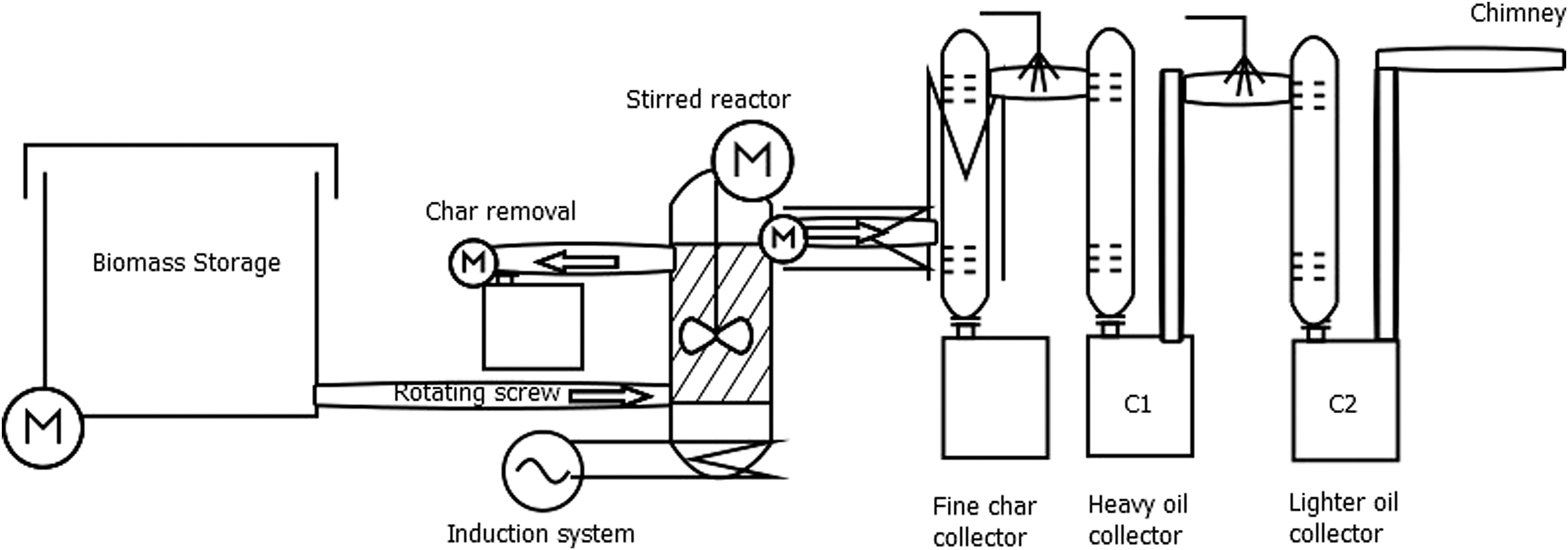
Schematic representation of the JUMBO MFR.
The biomass storage has a capacity of about 200 kg. The biomass is supplied to the reactor through a rotating screw. The screw is cooled with a water-cooling system to prevent heat excess that could lead to biomass auto-ignition in the storage. The storage is also equipped with a compressed air powered piston that prevents biomass bridging. It has been designed to allow a range of biomass to be fed in the reactor, up to pellet size (1 cm length, 6 mm diameter) particles.
The stainless-steel reactor is insulated and heated via an induction system. The latter is not realistic for industrial purposes as it requires high amperage (200 A) when starting the operations and then around 50 A to maintain the temperature. However, the fast heating of the reactor—up to 550°C in around 15–30 min—is a significant benefit and convenient for research purposes. The bed inside the reactor is composed of the char produced by the pyrolysis reaction and is fluidized via a mechanically powered impeller. This innovative technique results in a completely sand-free char comparative to traditional fluidized bed reactor, allowing for new high value applications.
A char-removal system placed at the top of the reactor extracts the char excess in the reactor through a rotating screw. The screw is also water-cooled to avoid char auto-ignition. The char is collected in a barrel.
The vapors exit the reactor from the top through an insulated pipe. An adjustable speed rotating screw helps control the flow of vapors. The pipe is maintained at 500°C to avoid any condensation of the vapors in this section. The vapors then reach an electrostatic precipitator (ESP). The ESP is also maintained at 500°C for the same reason. The ESP extracts small particles of char entrained by the vapor flow. The char is collected down the ESP in a barrel. Two vibrators placed on the wall of the ESP prevent the char accumulation on the ESP wall. To be efficient, the ESP needs to stay at a voltage above 10 kV.
The vapors then pass into a dual condensation system. The first condenser (C1) is operated at around 150°C with an ESP for aerosol collection. The second condenser (C2) is set around 100°C. The temperature is maintained using a water nozzle producing a mist at the exit of the first ESP. The mist provides a good mixing with the vapors while cooling them. Remaining (non-condensable) vapors exit through a chimney. In the future, recycling these vapors to provide heat to the reactor would be ideal.
The peripheric systems include nitrogen to purge the unit before starting, compressed air systems for the piston and vibrators, control panel to monitor the temperatures, and a water tank and pump for water cooling.
Biomass Properties
The biomass used for the tests is torrefied wood pellets from AIREX Energy. 28 Table 1 presents the main properties. Torrefaction is considered a promising pre-treatment to produce high-quality pyrolytic products. The rationale for using torrefied pellets is to minimize water content, leading to a higher quality bio-oil. In the future, non-condensable gases from the pyrolysis unit could be used to carry out a preliminary drying or torrefaction of the forest residues. Torrefied biomass is also more brittle, which should help facilitate the mechanical fluidization and heat transfer inside the MFR. 29 -32 In the future, various biomass are considered, with or without torrefaction as pre-treatment, and centered on forestry residues such as perturbation wood or unloved wood.
Torrefied Wood Pellet Properties
Pyrolysis Products Analysis
Sampling is done by homogenizing the total amount of products recovered after the run. A run average length is around 2–3 h, enough so a steady state is reached with around 60–80 kg of biomass being fed to the reactor. It is important to note that the unit is relatively new and therefore work is still ongoing to help smooth the operation and the runs.
All the pyrolysis oil analyses are performed according to established standards and protocols. Chemical and physical analyses were performed as stated by Tables 2–3. 33 -35
Standards for Chemical Analyses
Standards for Physical Analyses
Results and Discussion
The products obtained from the MFR, e.g., bio-oil and biochar, are characterized to determine the industrial possibilities offered for biorefinery and bitumen applications.
Bio-Oil Characterization
Physicochemical properties
Table 4 presents results obtained with two samples of bio-oils. As shown, water content differs from one condenser to another. It is relatively low for the oil coming from the first condenser C1 (∼ 8%wt), while it is higher in the second C2 (∼ 25%wt). This difference is expected and due to the lower condensing temperature of the second condenser. We can also observe that even though the first condenser was run above 100–150°C, a significant water fraction was collected. This result is not surprising, and consistent with what can be found in other fractional condensation train in the literature. 24,36 -38 Part of this fraction could be explained by the transitory state at the beginning of the trial, as well as interference during the trial as a pilot unit makes it more difficult to have smooth control over the condensation temperatures.
Bio-Oils Acidity
Acidity was measured in terms of total acid number (TAN) and not with pH due to the predominantly organic nature of the bio-oil. Values were obtained using a modified protocol of Elliot et al., and thus are given in milligrams of KOH per gram of bio-oil. 39 The first condenser shows a lower acidity (around 69 mg/g) than the second one (87 mg/g), as shown in Table 4. This result can be explained by a higher content in acids, particularly in acetic acid, caused by the lower temperature of the second condenser.
The bio-oils viscosity has been measured at a temperature of 75°C. At this temperature, the bio-oils are fluid enough to obtain accurate measurements. The viscosities of bio-oils coming from the two condensers are relatively close, at 34 cP and 16 cP, respectively. The viscosity of C1 bio-oil is higher, which is in agreement with a lower water content compared to C2.
Table 4 shows no major differences between C1 and C2 bio-oils in terms of ash content, density, and insoluble matter content. In the other hand, the solid fraction shows a significant variation with 7.6%wt for the C1 bio-oil and 0.3%wt for the C2 bio-oil. This can be explained by the design of the pyrolysis unit. Even though there is a hot ESP to collect biochar from the vapors, it is not efficient enough to prevent the contamination of the bio-oil by the biochar. Adding a cyclone collector and improving the design of the ESP should help to prevent such contamination.
NMR and IR analysis
Bio-oils are the complex result of an assembly of hundreds of active molecules. These compounds are very varied, and a wide range of chemical families are represented (i.e., ketones, carboxylic acids, carbohydrates). 40 In addition, chemical composition of bio-oils tends to change over time due to aging phenomena. Although it is impossible to know precisely the composition of an oil without going through various processes of extractions and/or purification, Nuclear Magnetic Resonance (NMR) and IR can provide a general idea. The results are detailed in Tables 5–6, and are valid for both C1 and C2 oils. Moreover, there is a perfect overlap between C1 and C2 spectra, both in NMR and IR.
1H NMR Results for La Tuque Bio-Oil, with C2 Oil Sample
13C NMR Results for La Tuque Bio-Oil, with C2 Oil Sample
For NMR analysis, all spectra are recorded in CDCl3 as deuterated solvent. Spectra recorded are in agreement with previous analyses (Table 5), acidity values measured being mainly due to acetic acid 2.10 ppm (Table 5).
For the acetone peak at 2.17 ppm—contrary to what we originally thought its origin—is not due to contamination of the glassware used, but due to biomass decomposition during pyrolysis. 32 For IR spectra (Fig. 2), all samples are analyzed directly on a Fourier-Transform Infrared Spectroscopy (FTIR) apparatus. 41 The huge signal observed at ∼3,400 cm−1 is due to water content as alcohol functions, in agreement with Karl-Fischer analyses (Table 4).

IR spectra of La Tuque bio-oil.
Aliphatic functions (CH, CH2 and CH3) appear around 2,800–2,900 cm−1, while ester and carboxylic acid functions are observed at 1,711 and 1,635 cm−1 respectively.
Thermal degradation
Thermogravimetric Analysis (TGA) have been performed with air to simulate the bio-oils thermal degradation (Figs. 3–4). Mass losses of around 66%wt and 34%wt are observed for the first condenser, respectively before and after 350°C. As to the second condenser, mass losses of around 82%wt and 16%wt are measured. The mass loss before 350°C is related to the degradation of cellulosic and hemicellulosic derivatives compounds, whereas lignin derivatives start degrading at around 350°C. 42,43 These results show that the first condenser gathers heavier compounds than the second one, which was expected due to the condensing temperatures difference. The strong mass loss below 100°C in the second condenser can easily be explained by the higher water content.
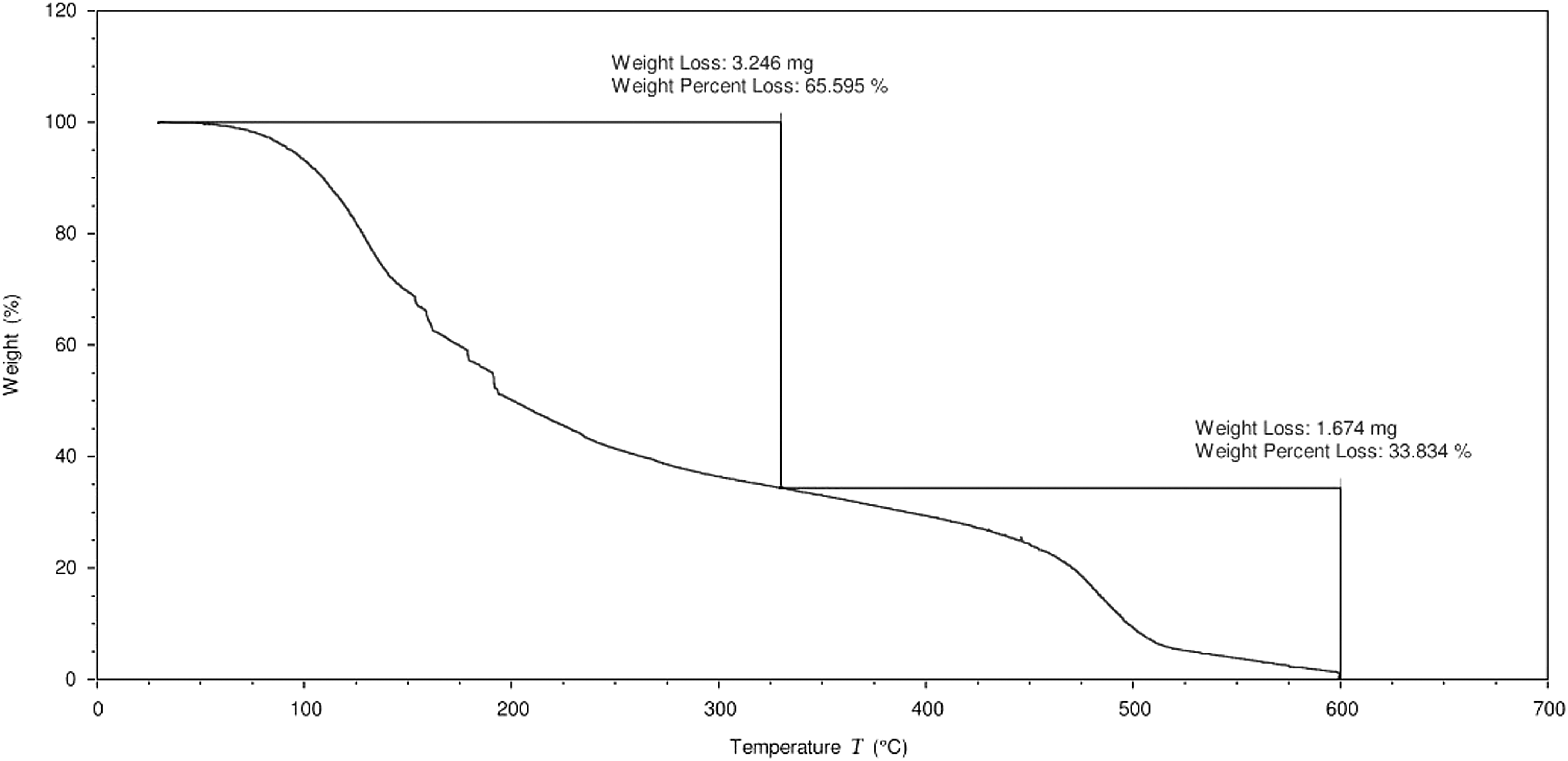
TGA of C1 bio-oil.

TGA of C2 bio-oil.
Char Characterization
Biochar is the second main compound obtained by pyrolysis. As for bio-oil, a full characterisation was performed (Table 7).
Biochar Main Physicochemical Properties
Results are obtained from 6–9 independent experiments from samples taken during the same run; aFor sulfur, values are below the detection limit.
For moisture and ash contents, experiments were achieved according to literature. 44 As expected, moisture and ash contents are very low. Moreover, the elemental analysis shows a very high carbon percentage (85%wt), which is in agreement with the internal temperature in the reactor during pyrolysis. 44 For TAN, the protocol chosen uses the same general principle as for bio-oils, with some adjustments due to the nature of the compound analyzed (fine particles). Due to the absence of sulfur (elemental analysis, Table 7), this acidity observed is mainly due to carboxylic acid functions. An electron microscopy study was also conducted. The results obtained allowed us to determine that we had very fine particles (on the order of a micrometer). In addition, as shown in Fig. 5, the pyrolysis process has preserved the porous structure of the wood, opening up a range of possible applications, such as acidic catalyst or activated carbon. 45,46

Electron microscopy of biochar; (
The bitumen industry has seen a growing interest for bio-oil applications in recent years, 13,14,47 -49 driven by increasing costs of raw petroleum-based materials and by the decreasing share of bitumen coming from more and more efficient petroleum refineries.
There are many different applications for bitumen, including asphalt or industrial bitumen, used for example for roof insulation and piping. 50 It is therefore difficult to define a precise list of properties that are required for a bio-oil to be used as bitumen replacement. Such a list would rely on the targeted application. However, some key points can be targeted as the most general and fundamental requirements. The first is the water content. Bitumen is processed at high temperatures, so the presence of water is a threat to the process stability and should be kept below 1%wt. Second, the acidity, expressed with the TAN, should be kept as low as possible to prevent extra corrosion and damages on the equipment. Third, viscosity should be high enough so that the product is not fluid at usage temperature, which can rise depending on the application such as pavement under summer heat. Fourth, thermal degradation should be minimal at usage and operation temperatures (usually up to 200°C). Finally, other parameters of the oil can have an impact depending on the applications and are also briefly discussed. 19
Both C1 and C2 bio-oil show interesting properties while C1 is the most interesting bio-oil based on its lower water content and therefore higher viscosity. Even though this bio-oil is promising, the remaining water, high acidity, and low viscosity prevent it from being used for most of bitumen applications. Furthermore, the remaining water content and high acidity combined with the high presence of solid residues is a strong indicator of powerful aging reactions potential. 51 Aging of C1 and C2 bio-oil is not covered by this paper, but should be investigated, as should upgrading pathways to make bio-oils more suitable for most bitumen applications and therefore increase its value.
Bio-Oil Quality for Biomass Densification
Biomass densification means that for a cubic meter of biomass transported in a truck, one needs to maximize the energy content to minimize the volume transported and the amount of transport needed (Fig. 6). 8 Therefore, it contributes to strengthening the environmental and economic viability.

Proportion of solids in forest fuels. 8
Table 8 shows the differences in energy efficiency between raw green forestry residues, wood pellets, torrefied wood pellets, and pyrolysis oil. Data for forestry residues, wood pellets and torrefied wood pellets come from the literature while pyrolysis oil data were measured from the bio-oil produced for this study. 9,15,28
Energy Values of Woody Fuels
Raw, unprocessed forest residues are very low in carried energy per m3 with 0.4 GJ/m3 to 0.6 GJ/m3. This low value is caused by the high water and oxygen contents in forestry residues. Wood pellets have considerably higher values: from 7.7 GJ/m3 to 9.9 GJ/m3 and from 11 GJ/m3 to 15 GJ/m3 (when torrefied). Pyrolysis oil enables an even higher densification with values ranging from 22 GJ/m3 to 29 GJ/m3. As expected, the stronger the thermal treatment is, the higher the energy value is. Gains are the results of improving the intrinsic fuel energy density by reducing the water and oxygen contents and improving the proportion of solid by enabling a more compact layout.
In terms of energy value, the low water content pyrolysis oil produced in this study is a good candidate for energy densification. However, standard and torrefied wood pellets might be stronger challengers when the economy is considered. This is because bio-oil transportation requires dedicated and more expensive truck; CAPEX and OPEX of pyrolysis plants are higher, compared to standard and torrefied wood pellets plants; the total mass/energy yield should be considered; the disposal of residual acidic water from pyrolysis plants should be considered; and the wood harvesting radius will impact on the final decision: the higher it is, the more adequate pyrolysis plants become.
Once all these factors considered and if economically competitive, low water content pyrolysis oil is an attractive option to create energy dense fuel from forestry residues that can be transported over long distances.
Conclusion
Bio-oil is a promising substitute to petroleum. However, it contains too much oxygen, which results in non-volatility, corrosiveness, immiscibility with fossil fuels, thermal instability, and a tendency to polymerize when exposed to air. Removing oxygen to upgrade oil appears as an elegant and simple solution, which would decrease water and/or acidity content. The JUMBO MFR pyrolysis unit enables the production of bio-oil with a low water content (8%wt). Nevertheless, the produced bio-oil is still too wet and fluid to be considered adequate for industries. However, a high acidity and significant thermal degradation below 200°C still mean that an upgrading step should be made, for example, through chemical modification, to avoid this limitation. The JUMBO MFR itself could also be improved to obtain bio-oils with lower water contents, higher compound separations, and fewer char contamination—all key to obtaining upgraded bio-oils.
Regarding biomass densification, such low water content bio-oil is promising, offering a much better energy density than pellets or torrefied pellets. Economic viability is nevertheless a key condition so that such a solution could be implemented in industrial-scale projects. Pyrolysis projects already exist in Québec, including Bioenergy AE Côte-Nord and Abritech.
Overall, the JUMBO MFR is a promising technology to produce high-quality bio-oil and biochar. Improvements to the technology regarding the sequential condensation of the vapors should make it even more appealing. However, questions remain regarding the scale-up possibilities of the mechanical fluidization system.
Footnotes
Acknowledgments
The authors wish to thank the team of Pr. Franco Berruti and Pr. Cedric Briens (especially Dr. Stephano Tacchino) for designing and developing the JUMBO MFR pyrolysis unit. Special thanks are also given to the team of Centre d'Études des Procédés Chimiques du Québec du Collège de Maisonneuve (CEPROQ). The authors also wish to acknowledge Dr. Agnès Lejeune for her expertise and work on the microscopy aspect of the project. Finally, the authors wish to thank all the financial partners including BioFuelNet, Economic Development Canada and Consortium de Recherche et d'Innovations en Bioprocédés Industriels au Québec (CRIBIQ).
Author Disclosure Statement
No competing financial interests exist.