
Abstract
Introduction:
Bronchoscopic spraying has potential for the application of therapeutic drugs in distal regions of the lung by bypassing the upper airways. However, there is a lack of understanding about the underlying fluid transport phenomena that are responsible for the intrapulmonary propagation of applied liquid.
Methods:
By using a transparent airway model, this study provides first experimental insights into relevant transport phenomena of bronchoscopic spraying. Furthermore, the penetration depth of the application is quantitatively evaluated. Laser-induced fluorescence is used to analyze fluid propagation in the transparent channels. Potential influencing factors such as the positioning in different airways, application number, breathing pattern, and lung obstructions are varied within this study to determine their influence on liquid deposition.
Findings:
This study shows that the method of bronchoscopic spraying allows the application of liquid in distal regions of the airway model. The position of the bronchoscope is a key influencing factor in increasing the penetration depth. We found that fluid transport along the distal airways essentially occurs by the film and plug flow phenomenon during application, which is similar to the transport mechanisms during instillation. Liquid plugs in lower airways are responsible for the reorganization of liquid during proximal movements and thereby influence the penetration depth in subsequent applications.
Introduction
During bronchoscopy, topical administration of active agents is routinely performed by application into the working channel of a bronchoscope using a syringe. 1 However, even distribution of the applied substance is difficult to achieve by this procedure. Thus, spray catheters have been developed, which allow nebulization of drugs during the bronchoscopy procedure using a constant oxygen flow. 2 These devices were initially designed for use during awake fiberoptic intubation, but can also safely be used during diagnostic bronchoscopies, as demonstrated in a clinical trial in which topical lidocaine administration through the nebulizer was investigated. 3
So far, the application of complex endobronchial therapeutic agents such as pulmonary cell therapy has been investigated using syringe instillation only. 4 While we developed a sophisticated spray device for endobronchial cell application, neither syringe, spray, nor nebulized endobronchial application has been tested with regard to the distribution of liquid in the airways.5,6 Existing data on inhaler devices are mostly based on simulation. While ventilation scintigraphy provides data on regional deposition differences, a procedure allowing evaluation of deposition by airway generation is lacking.
We developed an idealized transparent airway model made of fused quartz glass (see Fig. 1) that allows direct visualization of endobronchial fluid application. 7 In this study, we report on the propagation and deposition of fluid applied by a bronchoscopic spraying device, which was specifically designed for intrapulmonary stem cell therapy. 5 Note that in bronchoscopic spraying, the resulting droplets are significantly larger compared with nebulization. This is a necessary condition to ensure high survival rates of stem cells. However, with increasing droplet size, less distal penetration of the droplets is expected. Whether a high penetration depth can be achieved based on a bronchoscopic nozzle with bypassing the upper airways is investigated in this work.
Materials and Methods
Transparent airway model
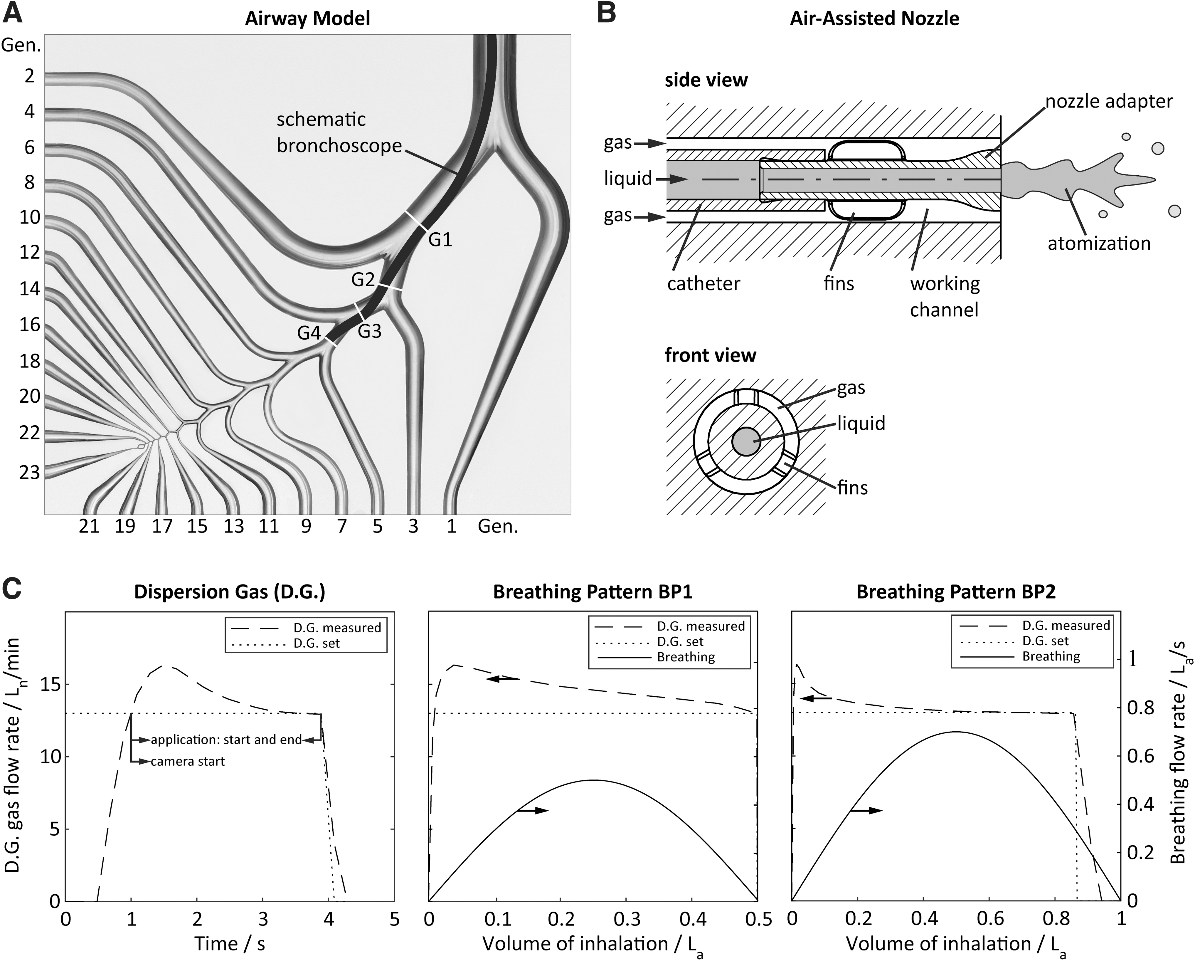
We recently developed an idealized transparent 23-generation airway model made of fused quartz glass (Fig. 1A). 7 It allows observation of film and droplet flows from the trachea to the 23rd generation in an idealized representative airway. Its airway geometry is based on the “Typical Path Lung Model” of the left lower lobe by Yeh and Schum 8 combined with the “Physiologically Realistic Bifurcation Model” (PRB) by Heistracher and Hoffmann. 9 The model is further simplified to a planar configuration with symmetrical bifurcations for ensuring an unrestricted optical access. The overall breathing pattern is generated by a piston pump and distributed to each generation with specific throttle-rotameter-systems (Omega Engineering, Inc., USA). Flow rates from generation 1 to 14 are separately defined in accordance with Möller et al, 7 while flow rates from generation 15 to 23 are summarized and adjusted by one rotameter (rotameter of generation 15).
In consistency with Longest et al, 10 an asymmetrical flow distribution is chosen for the lobar bronchi and a symmetrical one in the generations beyond. The airway model is positioned vertically, and hence, an influence of gravity on the penetration depth is expected. So far, the humidity and temperature of inhaled air in the airway model cannot be adjusted to physiological values, which influences the kinematic air viscosity (9% deviation between 21°C and 37°C) and droplet evaporation. 11
Bronchoscopic spraying device
For intrapulmonary fluid application, we recently developed an air-assisted nozzle adapter for combination with commercial bronchoscopes. 5 The nozzle adapter was designed for the atomization of stem cell suspensions with high survival rates. As shown in Figure 1B, the adapter is positioned at the bronchoscope tip (5.0/2.2 aScope™ 4 Broncho Regular, Ambu GmbH, Germany) and plugged into a catheter providing the liquid feed. The atomization principle is based on a shear flow between the liquid feed and annular gas stream, which is supplied through the gap between the working channel and nozzle. The radial nozzle position is stabilized by additional fins, ensuring constant atomization conditions.
A dispersion gas flow of 13 Ln/min (subscript “n” references to 0°C and 1013 mbar) is synchronized to inspiration. The dispersion gas is temporally regulated by a mass flow controller (EL-FLOW Select, Bronkhorst Deutschland Nord GmbH, Germany), triggered simultaneously with the beginning of inspiration and limited to 4 seconds.
In Figure 1C left, the temporal evolution of the gas flow rate is shown, indicating a delayed response time, followed by an overshoot of the flow rate with a maximum of ∼16.2 Ln/min and a convergence to 13 Ln/min. The dispersion gas flow is triggered simultaneously with the inspiration start. Once the dispersion gas flow rate exceeds 13 Ln/min (0.96 ± 0.01 seconds after inspiration start), the syringe pump (LA-110; Landgraf Laborsysteme HLL GmbH, Germany) is triggered, injecting a total amount of 1 mL with a flow rate of 0.4 mL/s for 2.5 seconds. We have recently shown that gas flow rates of 12.8 and 14.82 Ln/min result in stem cell survival rates of 80% and 63%, respectively. 5
Laser-induced fluorescence for visualization of fluid propagation
For visualization of the fluid propagation within the transparent airway model, we apply laser-induced fluorescence (LIF). Pyranine (Merck, Germany) is used as fluorescent dye with a maximum emittance at 520 nm and is dissolved in deionized water with a concentration of 0.05% (w/v). Note that this study is performed under the simplification that possible therapeutics are equally distributed in the deposited liquid after application and have minor influence on the spray characteristics. For dye excitation, the overall airway model is illuminated by an expanded laser beam (continuous-wave laser diode; Picotronic GmbH, Germany) with a central wavelength of 450 nm. The resulting fluorescence is observed using an electron-multiplying CCD camera (iXon3, Andor Technologiy Ltd., Northern Ireland; 1024 × 1024 pixel) with an objective lens (NIKKOR, Nikon, Japan; 50 mm d/1.2) and a filter combination for blocking reflected laser light (bandpass filter: 515 ± 10 nm, long pass filter: >475 nm).
Images are taken with 5 fps and 0.05 seconds of exposure time. The camera is simultaneously triggered with the start of liquid injection (Fig. 1C).
LIF image sequences are analyzed manually in terms of the maximum liquid penetration depth in the airway model. Bright pixel represents zones of fluorescence that are either caused by the accumulation of dyed liquid or by unwanted reflection of the fluorescent light at adjacent channels. To distinguish between both, the penetration depth is analyzed on the basis of temporal and spatial intensity variations in subsequent images.
Parametric study
The propagation of injected fluid is investigated in dependency of the position of the inserted bronchoscope, the breathing pattern, and a possible lung obstruction.
The bronchoscope is positioned along the airway in four subsequent generations (G1, G2, G3, G4), schematically shown in Figure 1A. The choice of tested generations is confined due to the outer diameter of the bronchoscope (5 mm). Due to the limited flexibility of the bronchoscope, its tip is either positioned on the upper or lower side of the straight cylinders, as specified in Figure 1A. In addition, two breathing patterns, BP1 and BP2, are compared (ref. Table 1). Simulated breathing patterns (inhalation and exhalation) are defined by the overall tidal volume and maximum flow rate (subscript “a” references to actual operating conditions at room temperature at 21°C and 1013 mbar) in the airway model. The combination of breathing pattern and dispersion gas evolution is shown in Figure 1C.
Chosen Breathing Patterns Are Based on Möller et al. 7 Tidal Volume and Maximum Volume Flow Are Characterized by Persons of Different Weight
In addition to the normal healthy state of the lung (open channels from 1st to 23rd generation), two special cases are studied: (1) a partial obstruction of the lung from generation 6 to 23 to simulate the effect of atelectasis (specified as case A for atelectasis) and (2) a complete obstruction of the lung (specified as case C for closed). Furthermore, the impact of multiple bronchoscopic spraying applications on penetration depth is tested in the abovementioned configurations by repeating the application five times (N = 5) in subsequent inspirations.
The overall measurement matrix is listed in Table 2. Each condition is repeated three times in total. After each experiment, the model is cleaned by flushing with deionized water and dried with pressurized air. In the experimental conditions of G1-BP1, G2-BP1, and G3-BP1, images are recorded for the time between application start and inspiration end. In all other experiments, the time is extended to the end of expiration for studying the influence of expiration on fluid penetration. The results of quantitative analyses are expressed as mean ± standard deviation.
Measurement Matrix on Bronchoscope Position, Breathing Pattern, and Lung Obstruction
Results
Qualitative description of liquid transport
The liquid propagation along the representative airway after intrapulmonary spraying is described below, based on exemplarily image sequences shown in Figures 2 and 3.
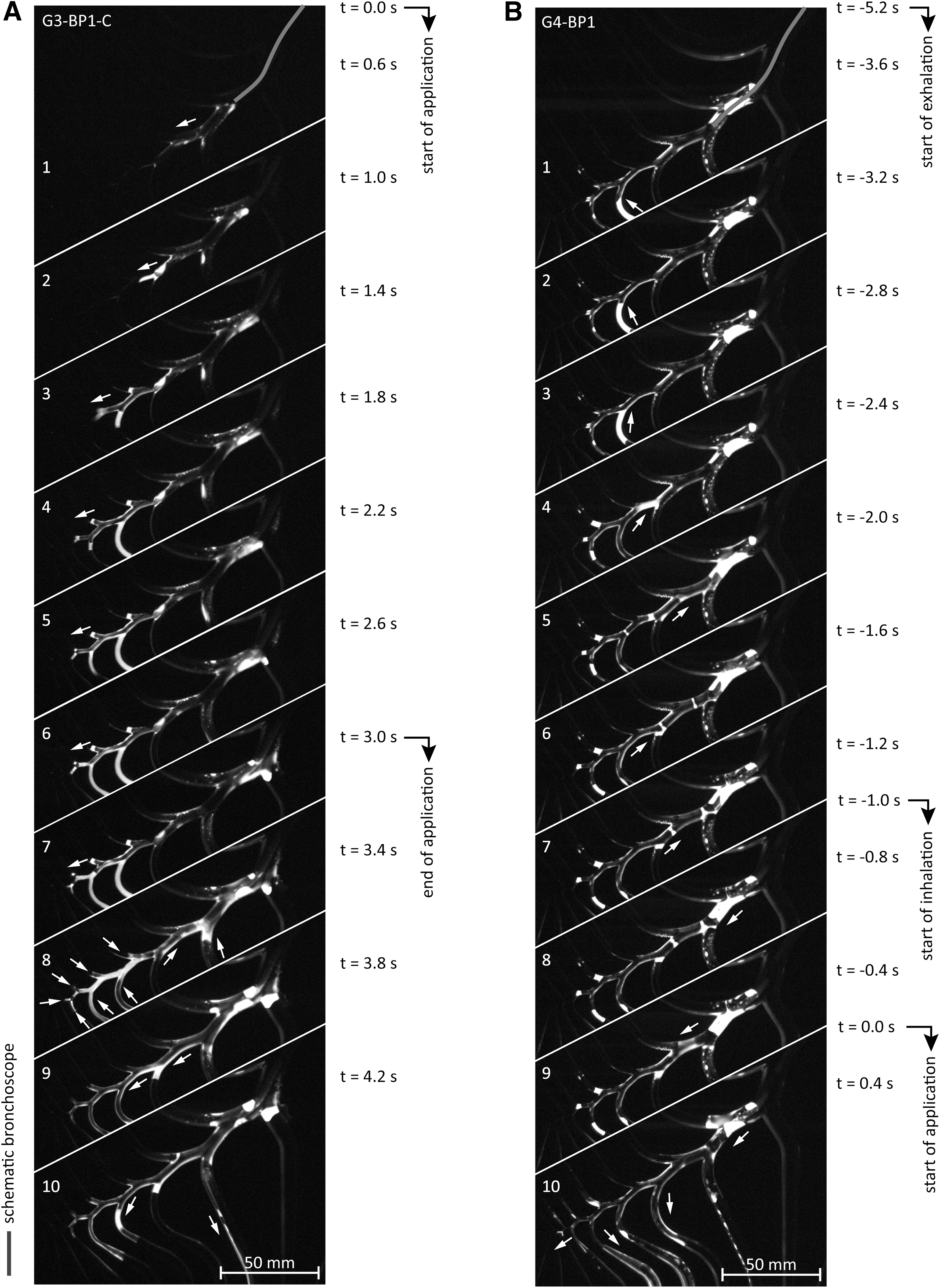
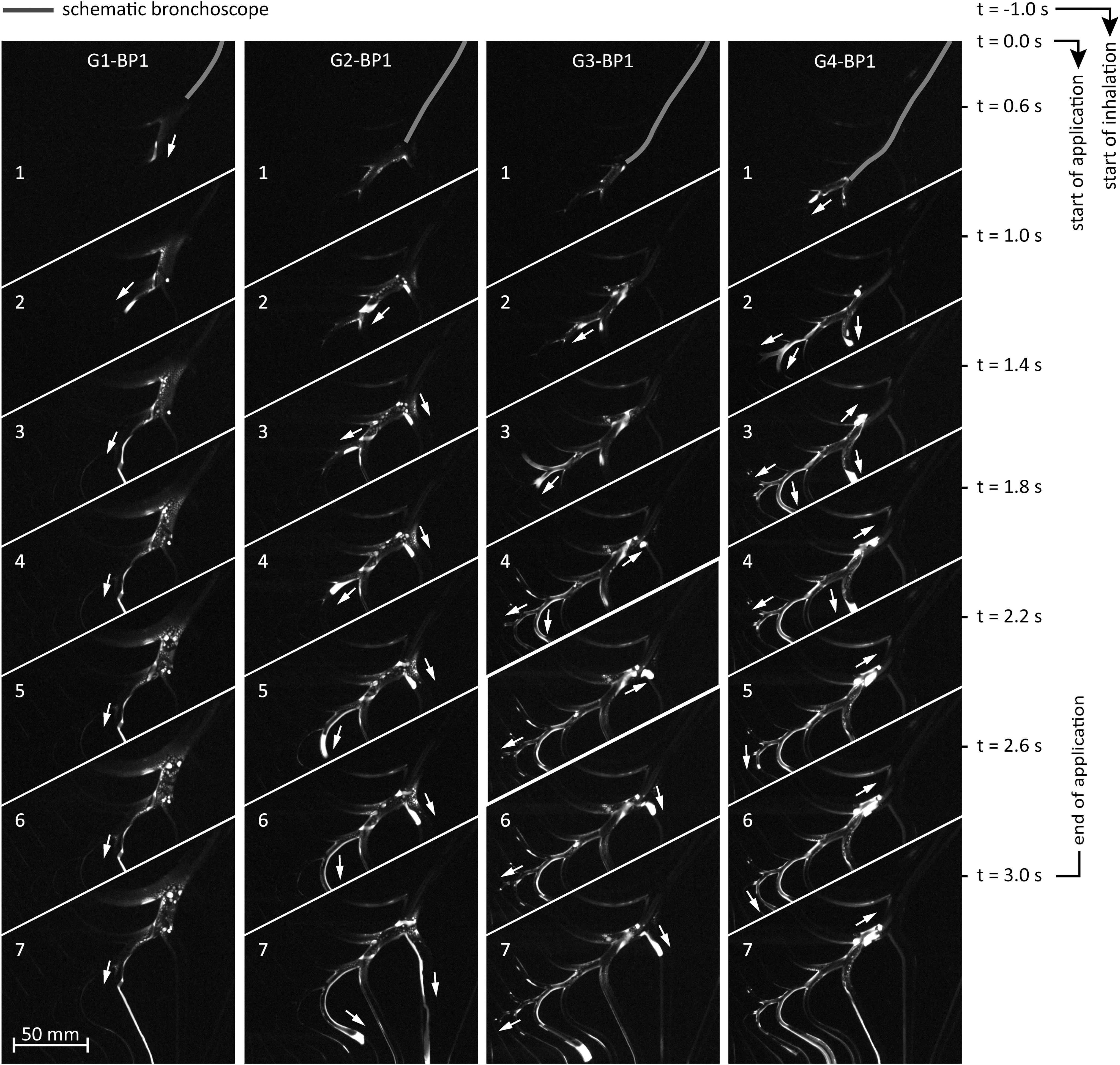
Exemplary image sequence of application processes for four different positions of the bronchoscope tip and for breathing pattern BP1. A maximum penetration depth is reached at the end of each application. The arrows indicate the directional movement of the liquid. Supplementary Videos (S1–S4) of the shown image sequences are given in the Supplementary Data.
In Figure 2A, the liquid propagation during application is shown for case G3-BP1-C. At the nozzle outlet, the liquid is atomized into droplets of a size of ∼50 μm in diameter. 5 However, since a macroscopic analysis technique was chosen, such structures cannot be resolved. Rather, the images show an accumulation of fluid directly at the nozzle outlet and downstream especially in the immediate vicinity of branches (c.f. Fig. 2A, No. 1 and Fig. 3, No. 1). At a certain accumulation on the channel surface, the liquid is pushed as liquid bulk into deeper airways (c.f. Fig. 2A, No. 2–7, indicated by blue arrows).
Depending on the volume of the moved liquid, the entire cross section of an airway can be filled up and the so-called fluid occlusions or liquid plugs are formed (c.f. Fig. 2A, No. 3–8). Since the diameter reduces with airway generation, plug movement is mainly observed in deeper airway generations. The maximum penetration depth is reached with the end of the application, that is, once the dispersion gas has stopped.
Instantly after application, a proximal movement of liquid plugs is observed (Fig. 2A, No. 8). A second proximal movement is seen at later times during expiration in nonobstructed airways. Due to this upstream motion, additional liquid plugs may be formed in lower generations (Fig. 2B, No. 5–8). Both proximal movements reorganize the position of the liquid in the representative airway path (i.e., by merging already existing liquid structures) and lead to the formation of new plugs or films. If stable plugs are apparent at the end of the reorganization, the subsequent application leads more likely to a deeper penetration into the airway model (Fig. 2B, No. 9–10).
Figure 3 shows a comparison of the penetration behavior for four different application positions, indicating a clear trend: with deeper application position from generation G1 to G4, the liquid tends to penetrate deeper into distal regions. A further flow phenomenon occurs in the application in positions G3 and G4 (Fig. 3, No. 3–7). The application is accompanied by backflow and accumulation of liquid directly at the bronchoscope's tip. Thereby it seems that the backflow in experiment condition G4-BP1 is larger than in G3-BP1.
Quantitative analysis of fluid penetration
Based on the parametric study, Figure 4 shows the maximum penetration depth as a function of possibly influencing factors. Quantitative information of penetration depths of each experiment is given in Supplementary Table S1.
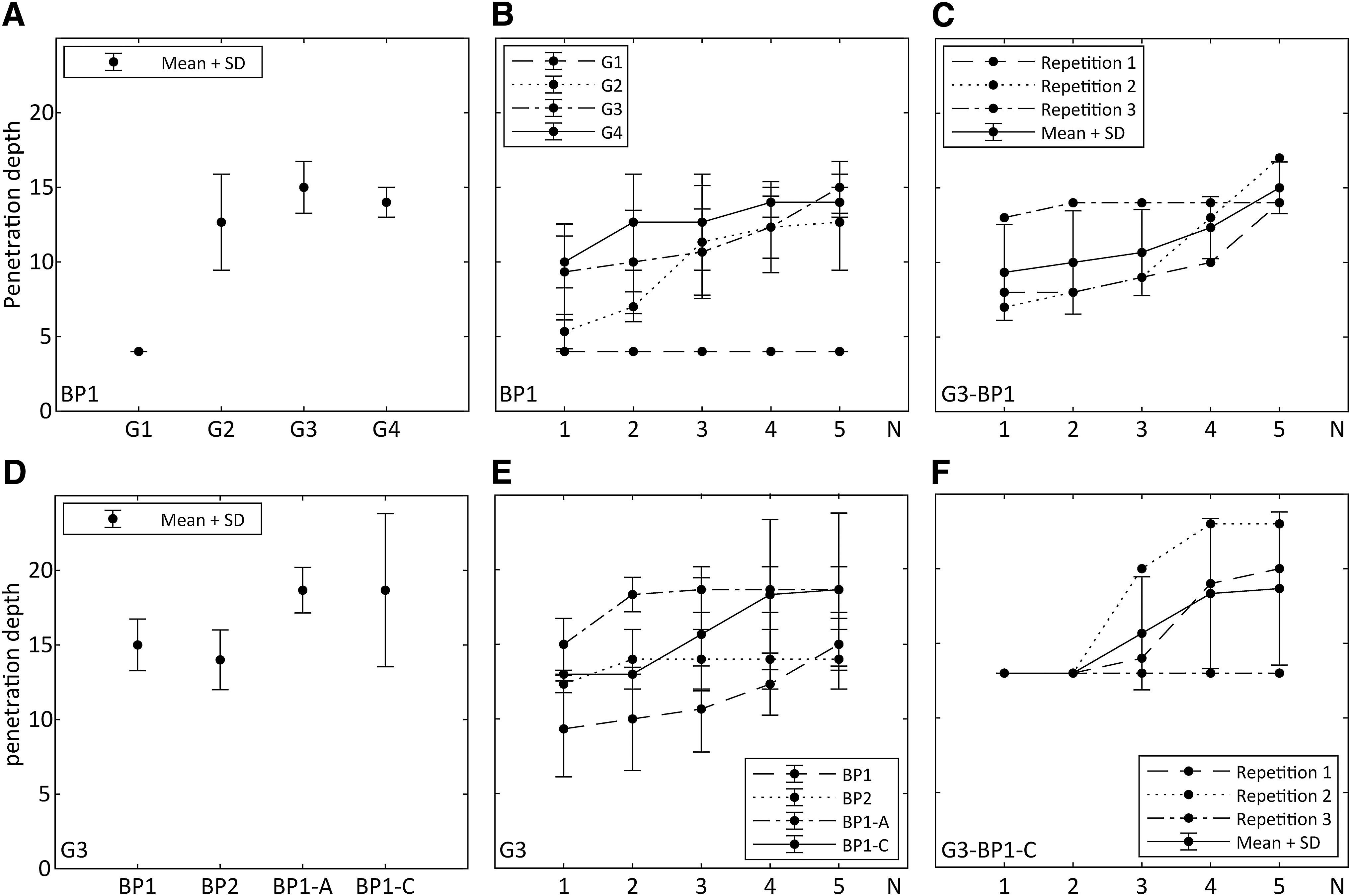
Upper row: Comparison of penetration depths for different application positions and breathing patterns BP1. Lower row: Comparison of penetration depths for different breathing patterns and obstructions.
Application position
The impact of application position on the final penetration after five subsequent applications is illustrated in Figure 4A. We can show that the maximum penetration depth is increased by moving the bronchoscope tip from generation G1 to generation G2. A further insertion of the bronchoscope has only a minor influence. However, bronchoscopic application in generation G3 exhibits the highest penetration depth.
Application number
In Figure 4B, the development of penetration depth is presented in dependency of the application number. Therein, except for G1-BP1, which shows a constant penetration depth, the depth of propagation increases with the number of applications. For better comprehensibility, the penetration depths of the three repeated experiments for conditions G3-BP1 and G3-BP1-C are separately shown and compared with the average values in Figure 4C and F. It highlights that the course of penetration depth is subject to strong variations. Further figures providing information of the other measurement conditions are given in Supplementary Figure S1.
Breathing pattern and lung obstructions
In Figure 4D, the influence of different breathing patterns as well as lung obstructions on maximum penetration depth is illustrated for an application in position G3. For cases G3-BP1 and G3-BP2, similar penetration depths are measured. Interestingly, with additional lung obstructions, the maximum penetration depth is further increased (G3-BP2-A and G3-BP2-C). The penetration depth rises with multiple subsequent applications (Fig. 4E), which is analog to Figure 4B.
Discussion
The liquid transport into deeper airways is not determined by atomized droplets, but mainly by liquid film and plug flow phenomena. This observation contradicts the expectations of a previous study assuming that transport and deposition of liquid are dominated by droplet deposition during inhalation. 5 The generated droplets are accelerated by the fast dispersion gas stream. Due to their high inertia, the droplets impact on nearby located internal surfaces such as the bifurcations. This impact leads to deposition and accumulation of liquid on the channel surface. In the further course, this liquid is continuously exposed to aerodynamic forces of the dispersion gas flow. Once the drag acting on the accumulated liquid is sufficient, it is pushed into distal regions of the airway model. During this propagation process, the liquid may occlude entire airway segments and liquid plugs are formed.
After application, we observe two different proximal plug flow phenomena: (1) compression-induced and (2) expiration-induced. These movements are only visible for liquid plugs since they exhibit a high flow resistance or drag in air flow. The compression-induced movement arises instantly after application. Evidence is given by condition G3-BP1-C with complete obstruction of breathing pattern (see Fig. 2A). This upward movement is presumably induced by the release of air in the side channels, which is previously compressed by the dispersion gas.* The overall process of liquid transport (proximal and distal) during bronchoscopic spraying is illustrated in Figure 5.
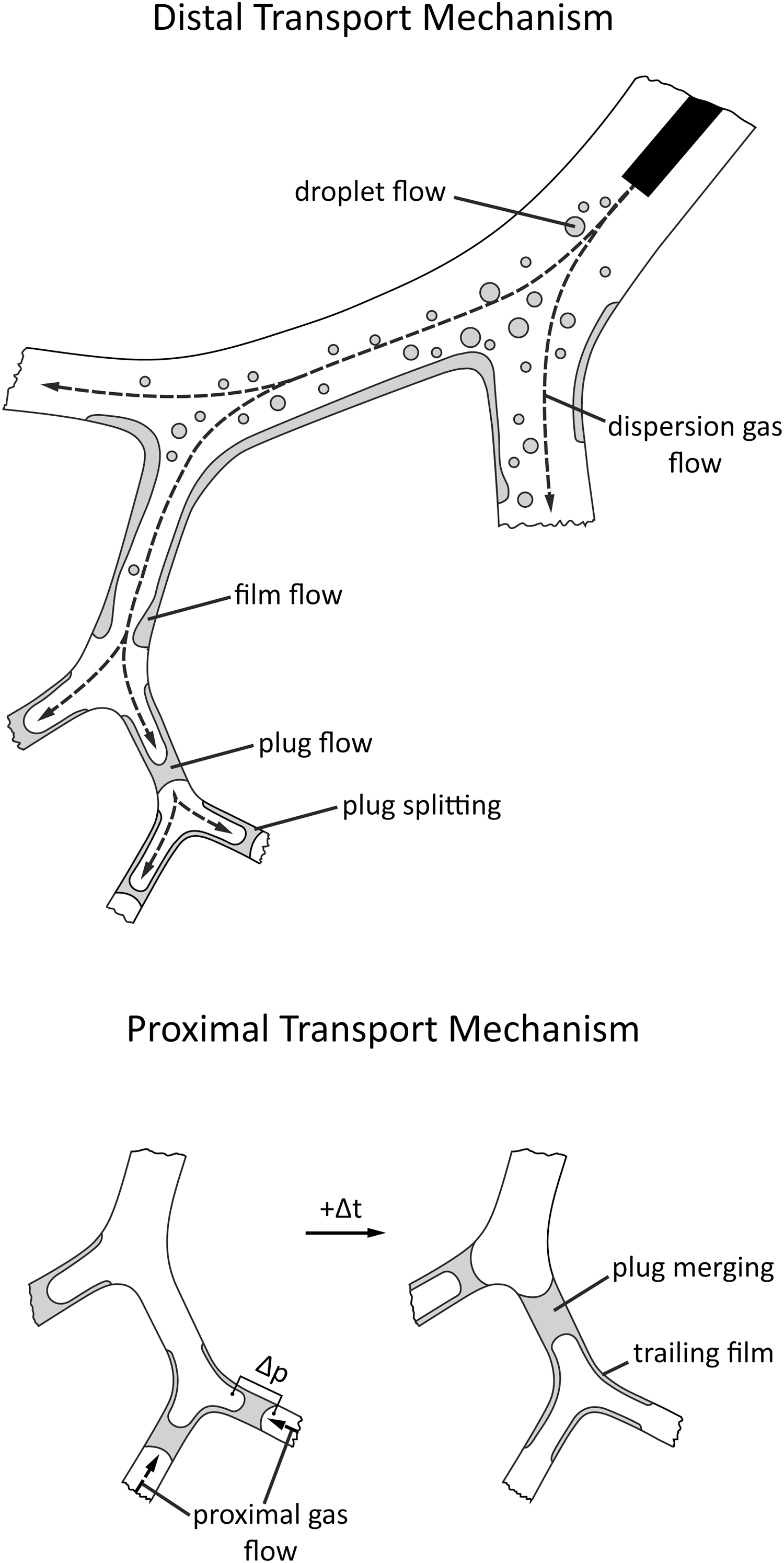
Observed liquid transport mechanisms during and after bronchoscopic spraying. The distal transport contains droplet flow, film flow, and plug flow. The proximal transport is determined by plug flows, which are induced by pressure differences (compression- or expiration-induced).
The observed liquid plug movement in distal airways reminds of the liquid bolus transport by intrapulmonary instillations.12–15 Similar flow phenomena are observed during instillation of radiopaque tracer in ventilated rat lungs by X-ray measurements: plug formation in distal airways and liquid reorganization forming new plugs through ventilation.14,15 Hence, the method of applying liquid by bronchoscopic spraying is phenomenologically closer to the transport mechanisms of instillation than to the inhalation of nebulized droplets. In case of stem cell therapy, stem cells are expected to be equally distributed in the trailing film behind the moving plug, considering a settling velocity of 2 μm/s and a maximum measuring time of 65 seconds. 13
The formation of stable plugs by liquid reorganization plays a major role in increasing the penetration depth of subsequent applications. Hence, multiple applications should be implemented in case of a potential treatment by bronchoscopic spraying. As seen in Figure 4C and F, the random increase of the penetration depth over subsequent applications indicates a stochastic process, which is depending on the occurrence of liquid plugs before and after proximal reorganization. Thus, no liquid occlusions are formed by bronchoscopic spraying in generation 1 (c.f. Fig. 3, G1-BP1); no increase of penetration depth over application number is observed. The formation of plugs in this application is per se stochastic; it depends on the previous local distribution of liquid in the airways as well as the closure time for forming a plug and the drainage time caused by gravity.15,16
The position of bronchoscopic spraying (G1–G4) is an important influencing factor for maximum penetration depth, which tends to increase within the tested positions with higher airway generations. The application in generation 3 is identified as optimized position for bronchoscopic spraying in terms of penetration depth, handling (insertion of the bronchoscope), and backflow.
Partial or full lung obstructions can lead to higher penetration depths than the reference G3-BP1. Due to the obstruction (no air flow by the breathing pattern), the liquid entering the representative branch is less pulled into the side channels. Hence, less liquid is drained out of the representative airway and a larger volume of liquid can be further pushed into the distal airways. However, the underlying mechanism should be proven with further experiments.
In general, the behavior of liquid in the airway depends on the interaction of liquid, air, and channel surface (wettability). In the human lung, airways are entirely coated with a mucus layer, which is a complex viscoelastic fluid containing primarily water and several additives as proteins, salt, lipids, and other surfactants.17,18 The airway model is manufactured in quartz glass and the surface-specific properties of the mucus are not simulated. Therefore, the draining of the liquid as also the development of fluid occlusions in the airway model might be different in comparison with the clinical application in the real lung.
Halpern and Grotberg 16 describe in a theoretical analysis that the closure time for the formation of liquid bridges is five times longer for a pulmonary surfactant-rich layer than for surfactant-free layer on the channel walls. In case of mixing between the bronchoscopically injected fluid and the surfactant-rich mucus, the probability of building up fluid occlusions could be diminished. In the long term, the relevance of the occlusion formation time on the transport phenomena should be further investigated by means of high-speed visualizations.
Conclusion
For the first time, liquid distribution after bronchoscopic spraying has been visualized in an experimental approach by LIF in a transparent airway model. Liquid transport into the airway model is mainly influenced by film and plug flow phenomena. Fluid occlusions play an important role in the reorganization of liquid during proximal movements and in the propagation of liquid in subsequent applications in the representative airway branch. A more distal positioning in the tested airway generations (G1–G4) leads to higher penetrations of liquid into the airways.
Author's Contributions
S.G., A.L.T., C.G.C., and M.A.R. planned the study. S.G. conducted the experiments. S.G., A.L.T., C.G.C., S.J., and M.A.R. contributed to the article. S.G. submitted the article.
Footnotes
Acknowledgment
The authors thank the German Research Foundation for funding the joint research project.
Author Disclosure Statement
The authors declare they have no conflicting financial interests.
Funding Information
This project was funded by the Deutsche Forschungsgemeinschaft (DFG, German Research Foundation)-Project No. 394605884 (RE 4092/2-1).
Reviewed by:
Pramod Kumar
Gerald Smaldone
References
Supplementary Material
Please find the following supplemental material available below.
For Open Access articles published under a Creative Commons License, all supplemental material carries the same license as the article it is associated with.
For non-Open Access articles published, all supplemental material carries a non-exclusive license, and permission requests for re-use of supplemental material or any part of supplemental material shall be sent directly to the copyright owner as specified in the copyright notice associated with the article.