
Abstract
Abstract
Objective:
Laparoscopic simulators help improve surgical skills in an ex vivo setting. New simulators incorporate force and motion assessment, but often at high financial cost. Our goal is to establish global access to a laparoscopic simulator, which offers both traditional summative assessment (time to task completion and precision) as well as advanced formative assessment (force and motion sensing capabilities) so that educators anywhere may be able to create simulators with increased educational value.
Design:
A low-cost laparoscopic simulator incorporating an off-the-shelf optical sensor, inertial measurement unit, holders, and a housing unit for a microcontroller was integrated into a plastic box with a high-definition digital camera and a three-dimensional mouse. Open source software was developed to offer real-time feedback in force and motion. The system was calibrated for accuracy and consistency.
Results:
The simulator was assembled from off-the-shelf components and open-source software. Total estimated cost was $350 United States Dollars. The mouse was calibrated by applying known forces in known directions. Linear forces measured in all axes showed linear output trends with r2-values of between 0.988 and 0.999. Accuracy in motion evaluation was evaluated and this demonstrated low average errors in the motion sensors of 5.4% to 6.8%.
Conclusions:
This low-cost, off-the-shelf, open-access laparoscopic simulator provides accurate and consistent measures of force and motion. We believe that collaborative efforts between surgeons and engineers can allow the creation of these surgical teaching devices at a reasonable cost such that they can be used in resource-rich and resource-limited settings.
Introduction
L
Analysis of motion in laparoscopic simulation can offer information about the smoothness and consistency of the operator's instrument handling, an important aspect of a surgeon's technique. Depending on the appropriately equipped simulator, incorporating the capability for motion analysis allows trainees to evaluate the path length, the number of hand movements, and the extreme velocity and acceleration events in the four degrees of freedom available in laparoscopy.11–13 Discrete analysis of these parameters allows for discrimination between skill levels and offers an additional strategy for the improvement of skills, and for formative assessment.12,13 Construct validity has been demonstrated for path length, motion in depth, and motion smoothness (or extreme motion events) for assessment of laparoscopic skill.14,15
The amount of force applied in laparoscopic surgery is difficult to assess in the absence of effective haptic feedback. Learning to use appropriate (but not excessive) force represents a particular challenge for trainees.16,17 Allowing trainees to see and understand their use of force during completion of laparoscopic tasks in simulators could improve their use of force intraoperatively. This may translate into a decreased potential for injuries from excessive use of force.18–20 Training with real-time force feedback has been shown to increase knot security, decrease the application of unnecessarily large forces, and improve overall tissue handling skills.21,22
Commercially available haptic or virtual trainers who offer motion or force feedback are generally expensive. The costs of these simulators vary from $500 United States Dollars (USD) to upwards of $15,000 USD, depending on the quality and feedback of the device.23–25 These prices can be prohibitive to individual surgical trainees or to surgical training programs, especially in resource-limited settings. In addition, these commercial devices have yet to implement pediatric models, and some do not provide continuous, real-time feedback.
Our goal is to establish global access to a laparoscopic simulator with both force and motion sensing capabilities. By designing an inexpensive open-source simulator, using simple off-the-shelf components, we hope that stakeholders in resource-rich and resource-limited environments will benefit.
Materials and Methods
The parts that are required to build this trainer cost ∼$350 USD. Hardware components include (1) the box itself, (2) an optical sensor, (3) an inertial measurement unit (IMU), (4) an optical holder, (5) a housing unit for the microcontroller, (6) a high definition (HD) digital camera, and (7) a three-dimensional (3D) mouse. There are two major pieces of software, (1) the firmware written to control the hardware, and (2) the application written for the user to interface with the simulator and collect data. The box was assembled as outlined below and then calibrated and tested.
Hardware
Box
The plastic box was assembled as outlined previously from 5 pieces of plastic, affixed together with a drill, 16 screws, and a screw driver, and is shown in Figure 1. 10 We designed box simulators of larger and smaller domains—the larger had a volume akin to that of an adult (50 × 37 × 18.5 cm), while the smaller had a volume akin to that of an infant (18 × 14 × 11 cm).10,26

Image of the full box trainer with both the left and right optical holders fully inserted into the box.
Optical sensor
Objects in free space can move through six degrees of freedom: three translations (heave, sway, surge) and three rotations (pitch, yaw, roll). Compared with open surgery, movement of instruments in laparoscopic surgery can only take place in four of these six degrees of freedom: one translation (surge) and three rotations (pitch, yaw, roll). This is illustrated in Figure 2. We used an optical sensor to measure roll (rotation around the instrument) and surge (the translation equivalent to movement of the instrument in-and-out of the simulator). The ADNS-9800 LaserStream gaming sensor is an optical sensor, which can accurately measure movement in the plane immediately opposite to its camera, and is available from multiple sources at a cost of ∼$28 USD per sensor. The sensor operates by acquiring sequential images of the surface directly below the camera and performing digital image correlation of the same point between successive images. The output of the sensor is a 16-bit number, which represents the movements of the surface in either the x- or y-direction in counts per inch (cpi). The sensor has a programmable resolution of up to 8200 cpi with steps of ∼200 cpi. The sensor also has a self-adjusting frame rate of up to 12000 frames per second (fps) and operates up to speeds of 150 inches per second and accelerations up to 30 g-force (g). Placing the sensors directly above the laparoscopic instruments allows simultaneous measurement of the roll and translation of the instrument along its longitudinal axis (Fig. 3). Similar mouse sensors have previously been used in tracking instruments during laparoscopic simulations. 26
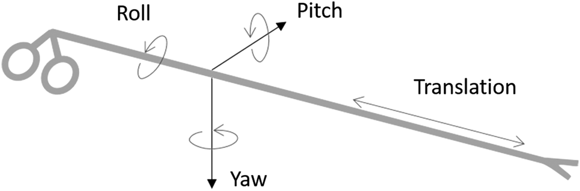
Illustration of the degrees of freedom measured for laparoscopic instruments.
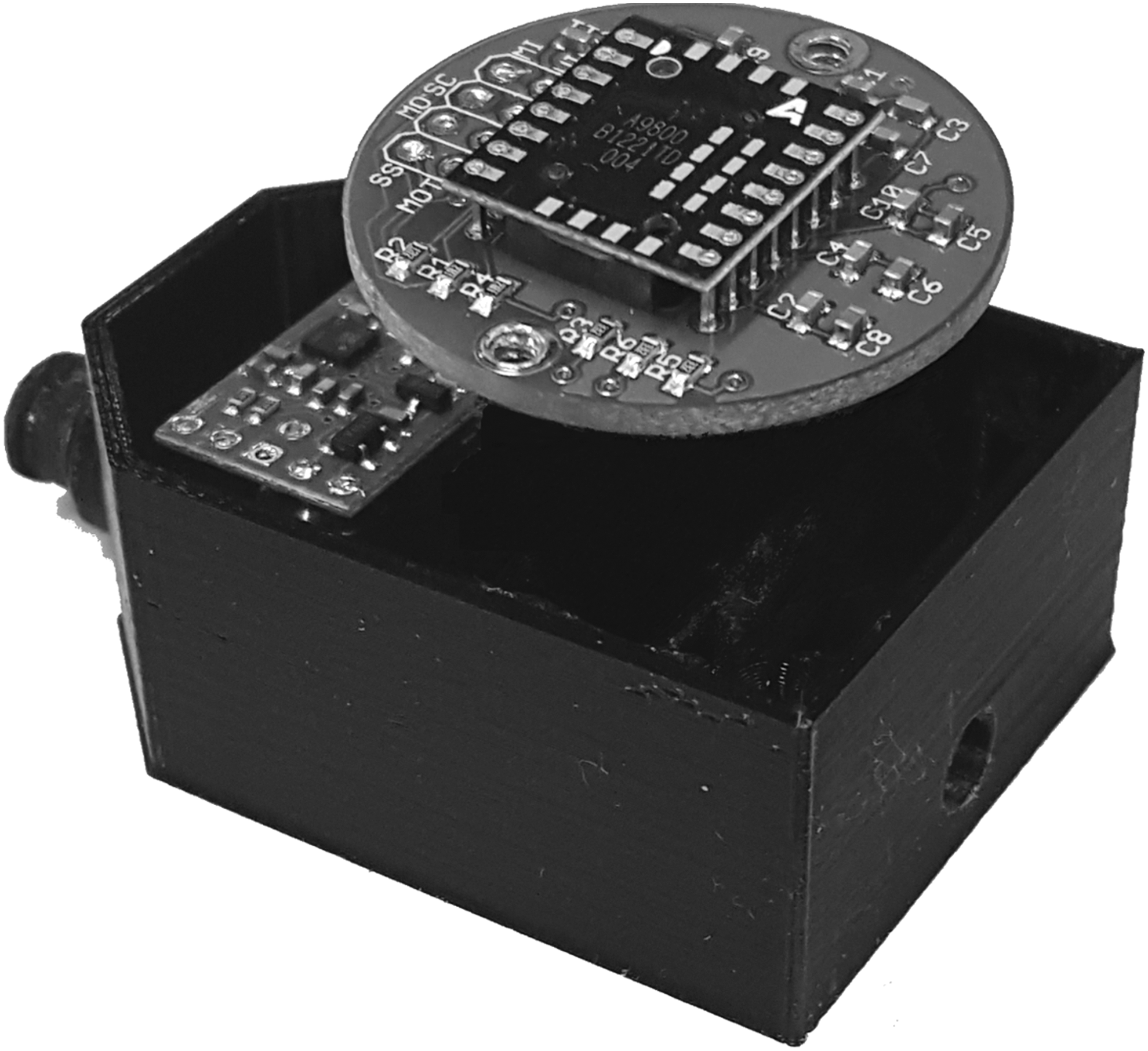
Illustration of the optical holder positioned above the instrument insertion port, which is used to determine changes in the position of both the optical mouse sensor as well as the inertial measurement unit.
Inertial measurement unit
We used an IMU to measure pitch (movement of the instrument left-to-right) and yaw (movement of the instrument up-and-down). The LSM6DS33 IMU is an always-on, 3D, accelerometer, and 3D gyroscope, which can provide acceleration and angular rotation data in three directions and is available for a cost of ∼$12 USD. The sensor provides six independent acceleration and rotation rate readings whose sensitivities can be set in the range of ±2 g to ±16 g and ±125/s to ±2000/s. Fixing the position of the IMU relative to the laparoscopic instruments allows us to measure the pitch and yaw (Fig. 3). According to the LSM6DS33 datasheet, when operating in the range of ±2 g, the accelerometer has a sensitivity of 0.061 mg/LSB (milligrams per least significant bit), and the gyroscope, when operating at ±2000 degrees per second (dps), has a sensitivity of 70 millidegrees per second per least significant bit (mdps/LSB).
Optical holder
Optical holders were 3D-printed and inserted into each box trainer to house both the optical sensors as well as the IMUs and to function as the instrument ports (Figs. 1, 3, and 4) at a cost of $20 USD per holder. The holder had each instrument port positioned inferiorly where the surgical instruments can easily pass through without obstruction. The holder rotates along with the instrument, allowing the IMU to be stabilized within the holder and to accurately monitor the pitch and yaw of the instrument. A small window was placed directly above the instrument port so that the optical sensor could be positioned to track the movement of the instrument through the holder (Fig. 4). The optical holders were attached to the box trainer by inserting the tip into the holes drilled in the front of the box where the operator would like the instruments to enter the box (Fig. 1).
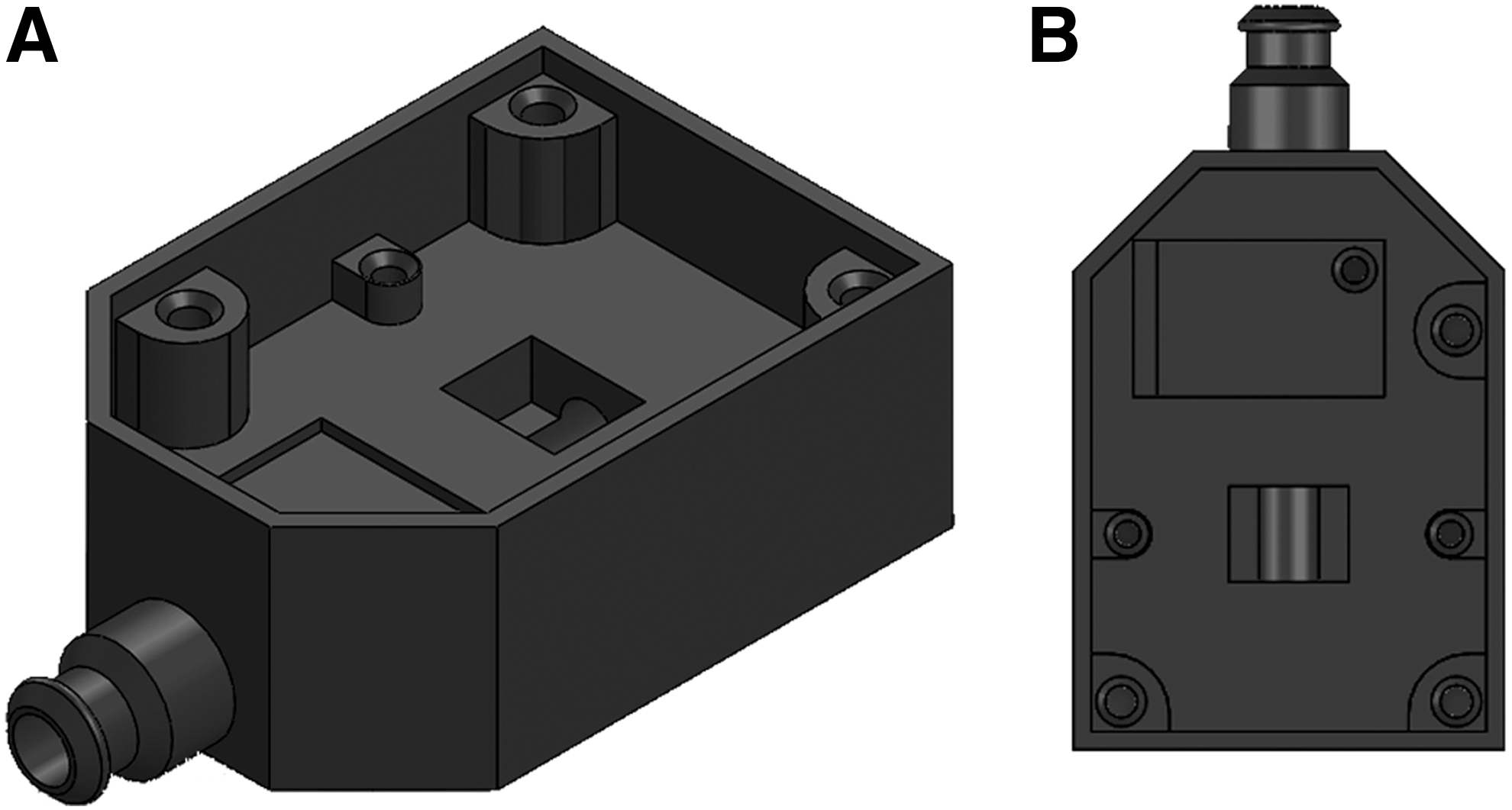
Schematic of the optical holder used to house the optical sensor and inertial measurement unit.
Microcontroller
The Teensy 3.2 microcontroller development board was used to interface the left and right IMUs and the left and right optical gaming sensors. The Teensy board is powered by a cortec-M4 Arm microcontroller (MK20DX256VLH7), which operates at 72 MHz and has both serial peripheral interface (SPI) and Inter-Integrated Circuit (I2C) communication protocols and is available from multiple vendors at a cost of ∼$8 USD. The SPI protocol was used to communicate with the optical mouse sensors, while I2C was used to communicate with the IMUs. The Teensy board is equipped with a micro-Universal Serial Bus (USB), which allows for both communication with the personal computer (PC) as well as 5 V power supply. As the Teensy board is directly connected to the PC via USB, which provides the 5 V power supply, no external power supply is needed to run the sensors or IMU. The board was programmed using open-source Arduino software, which is freely available here—https://www.arduino.cc/en/Main/Software. 27
3D mouse
To measure force, we used a 3D mouse (DX-700034 SpaceNavigator for Notebooks), which is manufactured by 3Dconnexion (MA) at a cost of $120 USD.16,26 This provided data on translational and rotational force in X, Y, and Z axes. The mouse was held in place by a second 3D-printed housing unit, which was fastened to an optical bread board (Fig. 5). The output of the mouse was calibrated to convert its movement into force measurements. This was achieved by applying a known force in each direction and mapping the output of the mouse to the applied force.

3D-printed Housing Unit to hold optical holders.
HD digital camera
We used a HD digital camera to record and transmit training videos in real time. We used the Microsoft LifeCam HD-6000 which has a high-speed USB camera with the ability to record video with resolutions up to 1280 × 720 and speeds up to 30 fps. It is available through multiple vendors at a cost of ∼$40 USD (Microsoft Corporation, WA).
Software
Java application
A Java application was developed to operate the simulator and is freely available online. 28 The application performs all of the data collection as well as displays the camera image to the user and allows the user to customize multiple features of the camera (Fig. 6).
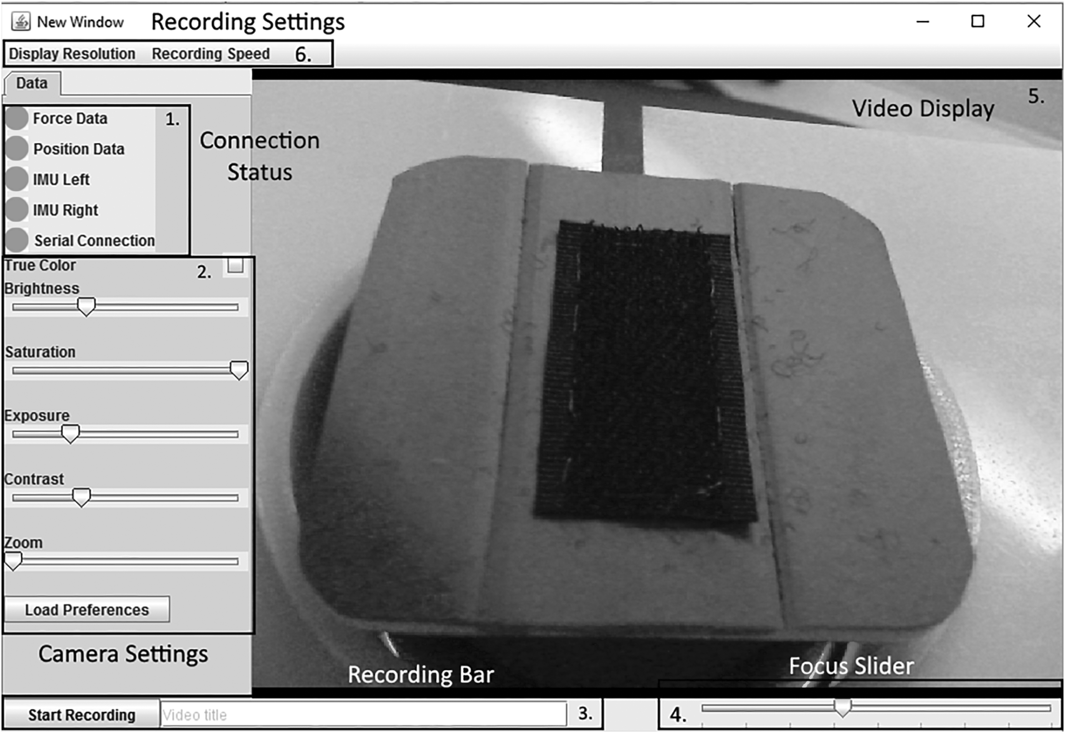
Screenshot of the graphical user interface developed in Java. (1) Connection status (2) Camera settings (3) Recording bar (4) Focus slider (5) Video display (6) Recording settings.
Serial data collection
The data collected by the Teensy was sent via serial connection to a laptop. The Java application immediately reads the data in the serial port by utilizing the java-simple-serial-connector library, developed by Alexey Sokolov. 28 Each serial read takes 5 ms, providing us with the location and orientation of each tool 200 times per second (200 Hz). After reading the data from the serial port, the data are saved to a “.csv” file for postprocessing.
Force data collection
The force data from the simulator was provided by the 3D mouse. When connected to a PC, the 3D mouse behaves as a game controller and can be interfaced in Java by using the Java input library. The 3D mouse is polled at a rate of 40 Hz, providing us with force in all three directions along with the torque about each axis every 25 ms.
Video display
The video images captured by the HD Digital Camera are displayed to the user via the graphical user interface (Fig. 6). The java computer vision (JavaCV) library was used to interface the camera with the java application. The JavaCV library was designed to make the functionality of commonly used libraries written for other platforms simple to use on a Java platform. This includes the open source computer vision (OpenCV) and Fast Forward Motion Picture Experts Group (FFmpeg) libraries. In our application, we used OpenCV to capture the images from the video camera and display them to the user. While the FFmpeg libraries were used to record the captured images by encoding them using H264 compression and saving it as an “.avi” file, H264 is a commonly used video compression algorithm designed to optimize the storage of video files with minimal losses in quality. The FFmpeg library allows for the adjustment of various video recording settings, such as the bit rate, frame rate, and type of compression. The current design uses a bit rate of 2000 kbits/s, a frame rate of 30 fps, and H264 compression. These can be easily adjusted to improve the performance of the simulator on PCs with varying specifications.
Calibration and Testing
3D mouse calibration
The 3D mouse was calibrated by applying known forces, and the output units were converted into Newtons (N). This calibration was achieved by applying multiple varying known forces up to 4 N in a single direction and noting the output. Forces applied to the mouse were monitored using a 10 lb load cell (Futek FSH00095, CA). Force was applied both to the mouse and to the load cell by means of a wire. This tension in the wire was increased incrementally, which resulted in greater force applied on both the load cell and the mouse (Fig. 7). This method was used to apply linear forces in the X and Y directions, and a torque force about the Z axis. A similar method was used to calibrate the torque forces about the X and Y axis. Instead of pulling on the mouse horizontally with the cable, a pulley was fixed to the housing unit, which converted the horizontal force to a vertical force, thus rotating the mouse. Finally, to calibrate for linear forces in the Z direction, calibration weights were placed directly on top of the sensor for the negative Z direction and hung from the top of the sensor for the positive Z direction.

3D mouse calibration setup for force analysis. 3D, three-dimensional.
Testing the optical gaming sensor
The accuracy of the motion measurements was tested by comparing the distance measured by the sensor with the actual distance traveled by the instrument. Distances tested along the longitudinal axis of the instrument were 50, 100, and 200 mm. The distance traveled by the instrument was verified using electronic calipers; each longitudinal distance was measured 10 times for both the left and right sensors. When testing the roll, the instrument was rotated 90, 180, and 360 degrees, which corresponds to 2.36, 4.71, and 9.43 mm for the 3 mm instruments and 3.93, 7.85, and 15.71 mm for the 5 mm instruments. Each rotation was repeated 10 times for both the left and right sensors.
Results
Mouse calibration for force measurement
Calibration of force in an X axis demonstrated a linear trend with an r2 = 0.988 in X > 0 and an r2 = 0.977 in X < 0, giving a highly accurate and easily convertible measurement of force (Fig. 8). For the Y axis, the Y < 0 and Y > 0 calibration also demonstrated a linear trend with r2 of 0.986 and 0.999, respectively. For linear forces in the Z axis, the Z > 0 and Z < 0 forces were also linear with an r2 of 0.997 and 0.999, respectively. While measuring the mouse output during rotational force, linear trends were also observed in the X and Y directions, and quadratic trends were observed in the Z direction (Table 1).

Mouse calibration for force measurement; trend between torque applied and force output in the X axis.
The three-dimensional mouse was calibrated by applying known forces and the output units were converted into Newtons. The conversion factors achieved by linear regression of multiple forces are illustrated for the X, Y, and Z axis.
Optical gaming sensor for motion analysis
The sensor located on the right-handed instrument showed an average error of 6.75%, while the sensor used for the left-handed instrument showed an average error of 5.4%. This corresponded to a minimal absolute discrepancy in distance measured and distance sensed to between 3 and 15 mm. The standard deviation for all of the positional measurements sensed was below 1 mm, indicating high precision in the measurements taken by the optical sensors (Table 2).
Mean error (%) indicated in bold.
The accuracy of the motion measurements was tested by comparing the distance measured by the sensor with the actual distance traveled by the instrument. Distances tested along the longitudinal axis of the instrument were 50, 100, and 200 mm. The distance traveled by the instrument was verified using electronic calipers; each longitudinal distance was measured 10 times for both the left and right sensors. The mean and standard deviation of the estimated distances are reported.
Discussion
We have designed and built a laparoscopic simulator with off-the-shelf, low-cost equipment and open-source software. We are excited to make it accessible for other interested stakeholders in surgical education in low and higher resource settings. The ability to measure motion and force in our simulator was calibrated and tested: good accuracy and precision were demonstrated. This open-source laparoscopic simulator is significantly less expensive than the commercially available products; its construction required a strong collaboration between surgical educators and engineers; ongoing enhancements will require this collaboration to continue. Interested stakeholders can now combine the software technology that is outlined in this publication with off-the-shelf hardware to create their own laparoscopic simulators capable of providing force and motion feedback; a lower price point allows this to be possible in resource-limited settings. We have assembled and provided these simulators to colleagues in Detroit, USA and have provided the specifications as outlined here to colleagues in Christchurch, New Zealand who successfully assembled their own set of simulators. As the box can be sized according to the trainee's requirements, it can be used to create either adult or pediatric laparoscopic simulators.
Currently, low-cost and low-fidelity box trainers are available who offer trainees the ability to practice basic laparoscopic skills and evaluate summative outcomes such as time to task completion and precision.9,29 The additional assessment of motion and force in surgical simulators has the potential to improve surgical skills outside of the operating room.30,31 Motion and force data derived from expert surgeons may then be used as a standard to which trainees strive and as a benchmark by which they may be assessed in the future. Additional training tasks which improve the trainee's use of force and motion have been developed, which rely on dynamic positioning and tissue manipulation analysis: these may be powerful adjuncts in the development of psychomotor skills.15,16 These formative metrics for assessment are becoming more popular in high-resource settings.17–19 However, current motion and force technology relies on virtual reality and haptic simulator systems to offer these formative measures. 32 Worldwide, these expensive modalities are not available to many surgeons and even fewer trainees, especially in resource limited settings.
Reproducing these simulators for trainees to incorporate the analysis of motion and force into their surgical training requires engineering and programming skills, which may not be readily available in all resource settings. The use of the simulator can be, however, contextualized: traditional summative metrics of time for task completion and precision can be routinely used, and if the requisite engineering and programming skills can be found, or developed, the advanced formative metrics of motion and force analysis may be incorporated. While the construction of the simulator requires the close interdisciplinary collaboration with an engineer who has programming skills, the impetus for its development and use will likely need to come from the surgical faculty, especially those who are surgical educators.
A limitation of this open-access simulator arises from the requirement for 3D-printed plastic components, which while reasonable in price in many countries, is not widely available in others. However, it may be feasible to source these 3D-printed instrument/optical holders from manufacturers of premade plastic cylinders of appropriate size.
The goal of this work has been to develop, and then, widely disseminate a laparoscopic simulator with capabilities for traditional (time and precision) and advanced (motion and force) assessment. The initial development of the simulator, calibration, and testing has been completed. We will continue our studies with further validation and technical improvements to streamline its construction and make it easier to encourage widespread uptake. We have shared our simulators and the technology with partners around the world. With specific regard to the motion and force technology, it has already been made available to stakeholders in Christchurch, New Zealand and Detroit, USA. Many others have simply adopted the formal simulators that we have constructed for them. Some of these stakeholders are working on applying our plans to their own context, which is our ultimate goal. We offer this publication to share our work in the international literature, hoping that motivated stakeholders will use the information to build simulators that are relevant to their financial and educational contexts and positively impact the training of their surgical residents and staff.
In conclusion, we report construction and calibration of a low-cost laparoscopic surgical simulator with force and motion sensing functions. We show validation of both the force and motion sensing functions proving the device to be accurate and consistent. We advocate for collaboration between engineers and surgeons to enable low-cost training incorporating force and motion analysis in any environment, whether resource-rich or resource-limited.
Footnotes
Acknowledgments
We thank all surgeons, engineers, residents, and students who contributed their time to the development and optimization of this simulator.
Disclosure Statement
No competing financial interests exist.