
Abstract
Abstract
This article presents results of computer simulations of the hydro-mechanical processes in the lymphedematous tissue under stress of a single chamber of sleeve for pneumatic compression. The discussion was focused on parameters of compression as pressures and inflation times to squeeze out the mobile tissue fluid from the edematous tissue. Simulations have predicted that the process of squeezing of tissue fluid is strongly dependent on the pressure in chamber and time of its action. The simulations showed that the values of loads and time applied in currently used pneumatic compression systems are not sufficient to force complete outflow of mobile fluid and pressure dissipation in limb swollen soft tissues.
Introduction
L
In order to move the stagnant fluid along tissue channels to areas without lymph stasis, as arm or hypogastrium, external forces should be applied. The most effective proved to be those generated by intermittent pneumatic compression (IPC). The pneumatic devices produce tissue fluid pressure gradients to facilitate its flow. A number of pneumatic devices have been constructed. The technical parameters of these devices are usually based on blood rheological data derived from textbooks. These are the capillary and venous blood pressure, tissue venous blood flow and capacitance, capillary filtration rate, and laser-measured capillary flow. Based on blood pressure/flow data, the recommended compression pressures for treatment of lymphedema do not exceed 50 mmHg, time of compression by a sleeve chamber remains around 5 seconds, and it is followed by rapid deflation.
The question remains unanswered whether the applied parameters are effective in evacuating tissue edema fluid and restoring normal hydration of tissues. The efficacy of compression in moving fluid depends on hydraulic parameters of the interstitial space in the massaged tissues and, in particular, the tissue fluid pressures/flows and hydraulic conductivity. It is known that the minimum tissue fluid pressure initiating fluid flow is above 30 mmHg. 3 Would this pressure be sufficient for evacuation of excess edema fluid? This would be difficult to prove in vivo. Therefore we decided to design a simulation model.
In this article we present simulation results of the hydro-mechanical processes in the lymphedematous tissue, under action of a single not moving chamber of the sleeve for pneumatic compression. The results obtained from this simulation model could give more insight into the distribution of applied force and the time necessary for displacing fluid, as well as the degree of deformation of tissue under and proximal to the inflated chamber.
Biot's model of poroelasticity4–7 and the finite element method implemented in Comsol Multiphysics environment 8 were applied. Parameters of the model that describe real properties of human edematous tissue are hardly available because most studies of the tissues were focused on animals 9 and did not take into account the two-phase nature of the materials, particularly the different properties for drained and undrained conditions. The parameters are also not available for currently used in vivo noninvasive techniques. 10 The stiffness of edematous tissue has been approximated by stiffness determined for human subcutaneous or adipose tissue,11–16 while estimated hydraulic permeability is based on in vivo measurements. The limb is modeled as a cylinder with a layer of constant thickness edematous tissue. For a given set of geometrical parameters of limb, material parameters of tissue and selected values and time of applied pressure in the chamber of sleeve the distributions of pore pressure and fluid velocity, as well as displacement of tissue, were analyzed. The simulation should give preliminary answers whether the poroelastic model of soft lymphedematous tissue can predict the observed tissue behavior in the pneumatic compression and if the parameters of currently applied compression systems are properly selected.
Methods
Data for the simulation model
The simulation model was designed for a device produced by Biocompression (Moonachie, NJ)2,3 with a sleeve composed of eight chambers, each 9 cm long. Sequentially inflated, inflation pressures were regulated from 50 to 120 mmHg. In this study, simulation of fluid pressure and velocity, and tissue deformation under one mid-calf chamber was designed.
Mathematical description
The simulated system
The simulations were focused on hydro-mechanical processes in the lymphedematous tissues under the load of a single chamber of sleeve for pneumatic compression. In Figure 1, the assembly half-section of the simulated system that comprises a part of limb with length L under the load of half of a single chamber of the sleeve is shown. It is assumed that the limb has a cylindrical shape with constant radius Re and the tissue has thickness d. The load on the tissue constitutes homogeneous pressure applied from the chamber pc. Assuming the symmetry of the process for considered geometry and single chamber case, only half of the chamber with size H is taken into account. In modeling, a cylindrical coordinate system was adopted with axis z along the limb axis, and axis r perpendicular to the circumferential surface of tissue. It is assumed that the soft tissue can deform under load (pressure in the chamber pc) and the material inside the ring of soft tissue is not deformable and constitutes a rigid core.
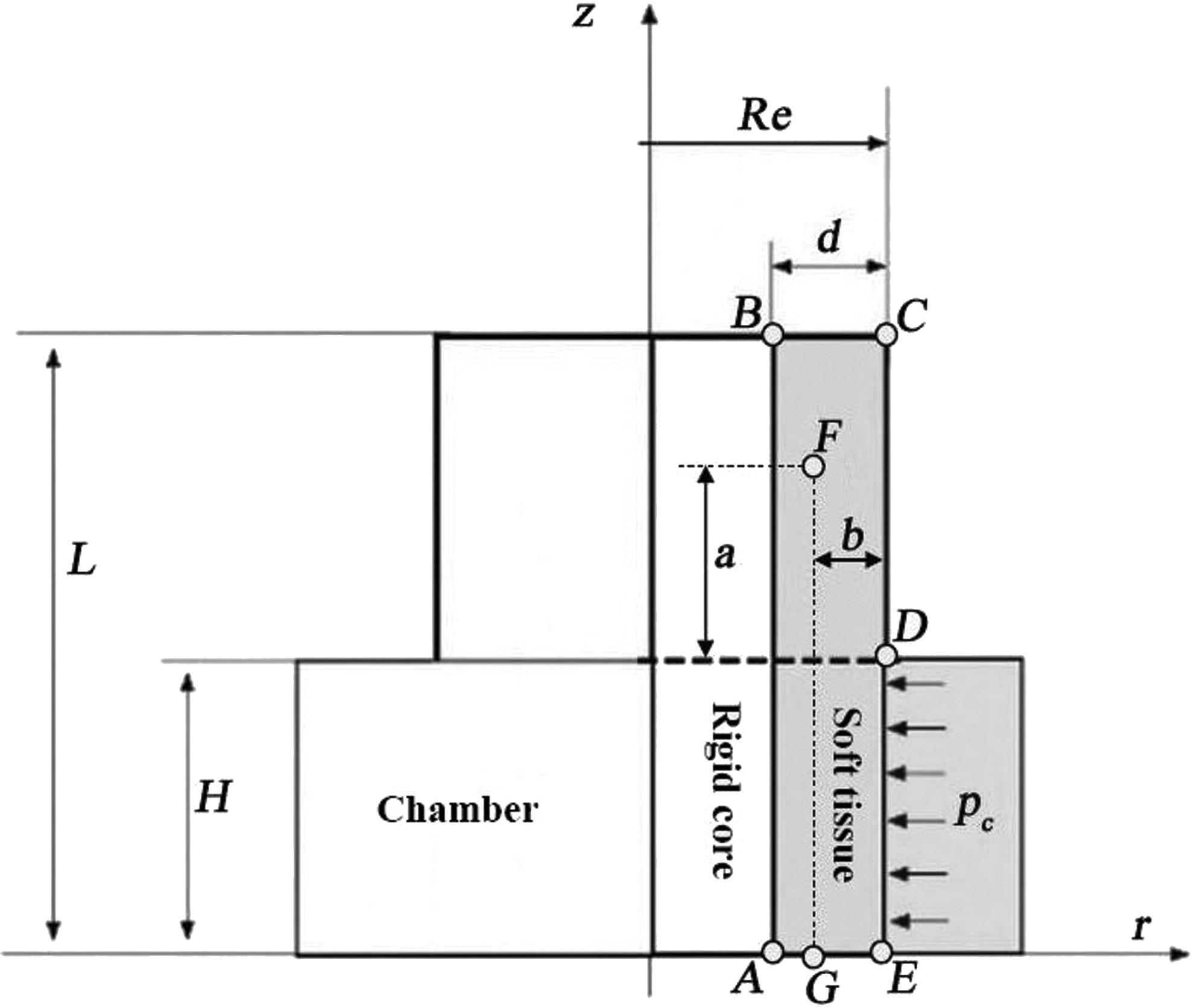
Schematic presentation of the simulated system—a part of limb under load pc. The tissue has cross-section ABCE, and F and G are control points.
Model of tissue
For the performed simulations we assume that lymphedema is a disease with damaged walls of all lymphatics. Our previous studies show that from stage II to IV of the disease, albeit some lymphatic fragments may be visualized, their hydraulic capacity is nil. Taking this into account, we postulate that edematous tissue has properties of soft biological material with tissue fluid that fills its interstitial space. In order to incorporate independent motion of tissue fluid and solid component, it is assumed that the tissue can be modeled as a two-phase material–liquid saturated porous medium. 9 Under the action of a load, the skeleton of the material can deform, and liquid can move in connected (permeable) pore space. Assuming that the skeleton is homogeneous, isotropic, and has linear elastic properties, and flow of liquid is associated with presence of interaction force between the liquid and skeleton proportional to the relative flow velocity, we applied as the model of tissue the Biot's model of poroelasticity.4–7 The model neglects the components of viscous stress in fluid phase. This is justified because the components are needed only for cases when the volume fraction of moving fluid is high and for the soft tissue most of the fluid is bounded (in cells and in extracellular space) and the percentage of moving fluid is low. There is a moderate or low hydraulic permeability of the tissue (of the order of 10−13 m2). The values of the latter quantity are assumed to be constant despite the deformations of subcutaneous tissue. The model assuming the constant value of hydraulic permeability is a first approximation; future progress in studies of the parameter will give a chance to improve the model.
Initial and boundary conditions
We assume that initially the solid skeleton and pore liquid are not loaded, and as the result the skeleton displacement and pore pressure are equal to zero. The boundary conditions for the modeled system are specified by the characteristic points A, B, C, D, E, shown in Figure 1, and are as follows:
a) There is no flow through the boundaries AB (contact with muscle), CE (skin), and AE (symmetry plane). The flow is possible solely throughout the boundary BC, b) The tissues at the boundary AB cannot displace in directions r and z. The tissue at the boundaries BC, AE, and DE can displace in radial but not in axial direction. There is no constraint for the tissue displacement at the boundary CD. c) The load on the tissue is applied by a pressure in the chamber pc at the boundary DE. The pressure is equilibrated by the normal component of the total stress at this boundary, which is distributed between the solid and fluid phase according to Biot's effective stress law.
4
Initially the pressure in the chamber is equal to zero and thus there is no necessity to specify the initial load distribution between pore fluid and skeleton.
Additionally, the locations of two control points F and G are shown in Figure 1. The pore fluid pressure and velocity changes in time will be analyzed at these points.
Results
Applying the model of poroelastic soft tissue and initial and boundary conditions for the modeled domain given above, along with the parameters that characterize geometry, material, and the load specified in Table 1, simulations were performed with help of the finite element method. Calculations were done using COMSOL Multiphysics environment with modules allowing application of poroelasticity equations.
The Poisson's number of the tissue 0.33 was taken from the published data for soft tissues (e.g., brain).7 Young modulus of the tissue was assumed following studies for human subcutaneous or adipose tissue.11–16 The value for porosity was 0.05, the lowest possible as it did not play any evident role in slow fluid flow. Liquid density, compressibility, and viscosity were that of water. Hydraulic permeability data originated from own studies.
Parameters for simulations
The numerical solution of the considered initial-boundary value problem required specific parameters characterizing geometry, load, and material. The list of parameters are given in Table 1. It was assumed that the tissue layer is 3 cm thick and the external radius of its ring amounts 8.8 cm (girth 55 cm).
The length of the considered piece of limb is assumed to be equal to 10 cm, while on its length of 4.5 cm acts the load originating from the sleeve chamber (half of its total width). The load on the tissue was exerted by pressure inside the chamber, which increased during the first 5 sec linearly from zero up to its target value and then was kept constant. Four cases of the total time of loading: 10, 20, 50, and 600 sec were considered.
The target values of pressure inside the chamber pc were 50, 80, 100, or 120 mmHg. The parameters characterizing tissue as a porous material were selected based on a thorough review of literature, although it should be noticed that the available materials do not offer complete information about the structural and mechanical properties of lymphedematous tissues. Thus, it is here assumed that soft edematous tissue is homogeneous and isotropic, and has properties similar to human subcutaneous or adipose tissue. The Young modulus (E) for such tissues amounts between 0.12 and 50 kPa11–16 and the value 25 kPa was used. The Poisson's number (ν) was assumed equal to 0.33, taking into account drained conditions for the considered simulations. The hydraulic permeability (K) of the tissue was estimated based on in vivo measurements using technique described in Ref. 17. Porosity (φ) of the tissue was assumed equal to 0.05 and parametric studies have proved that results of simulations are not significantly influenced by the parameter. The mechanical volumetric coupling (αb) was postulated to be equal to one and this is in agreement with Terzaghi's effective stress principle. 8 The parameters describing interstitial liquid: density (ρ), compressibility (Kf), and viscosity (η) were taken as for water.
Distributions and time dependencies of pore pressure and fluid velocity
Spatial distributions of pore pressure in the interstitial liquid for four levels of loads on the lymphedematous tissue (50, 80, 100, and 120 mmHg) and four periods of simulations (10, 20 50, and 600 sec) measuring from the beginning of the applied load are shown in the contour plots Figure 2a-d. The time dependence of pore pressure in two control points of tissue F and G placed at the depth of 2 cm from the external surface of tissue layer are presented in Figure 3.
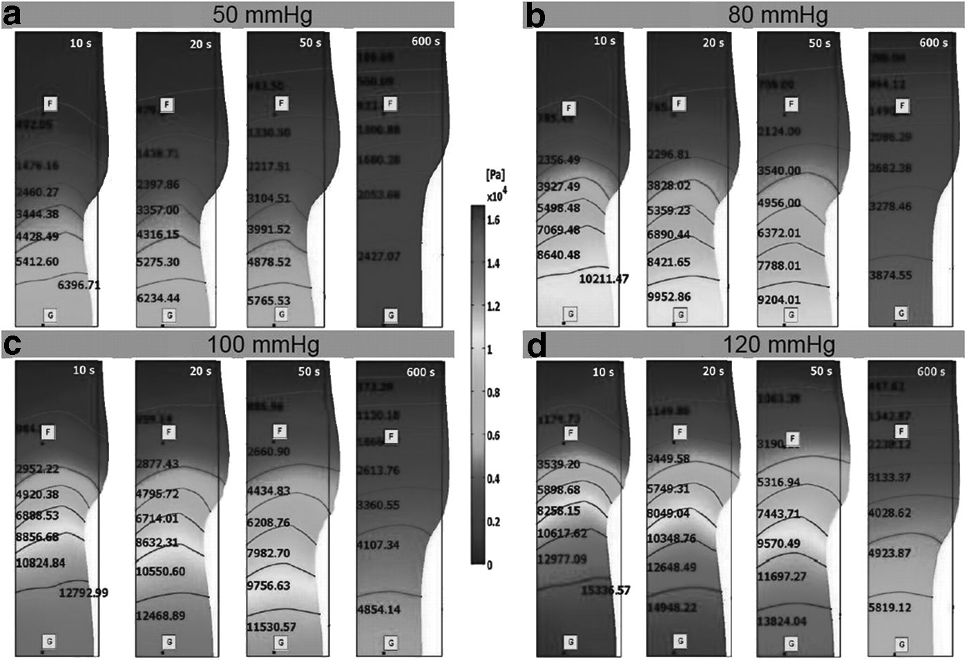
Dependence of the tissue fluid pressure on a position within the simulated piece of tissue obtained for different pressures applied in the chamber: 50 mmHg
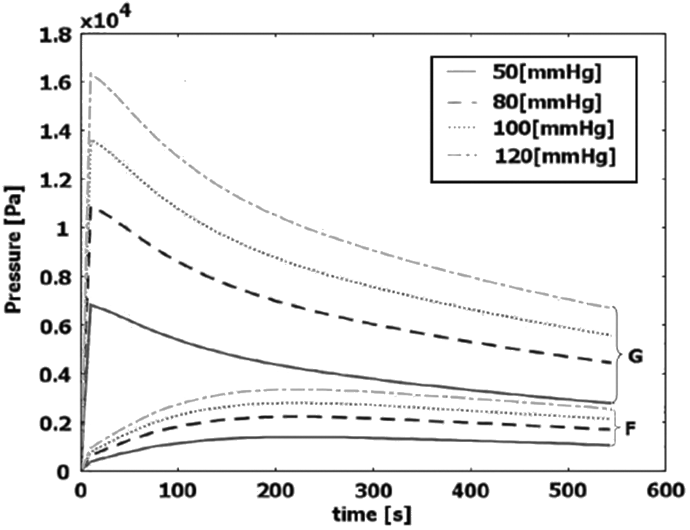
Dependence of the tissue fluid pressure on time at control points G and F located in tissue under and next to the chamber, respectively (see Fig. 1). The results of simulations are shown for four different pressures in the chamber: 50, 80, 100, and 120 mmHg. The tissue fluid pressure under the chamber (point G) is initially very high and gradually decreases, but its value for 50 sec is no more than 30% lower. The tissue fluid pressure next to the chamber (point F) remains for the whole time much lower than its values under the chamber.
The results of simulations showed that, according to the poroelastic model, initially after application of pressure in the chamber, the pore fluid assumed substantial part of the load (the distribution of the initial load between pore fluid and skeleton was determined by parameter αb). It can be seen as high pressures in the part of simulated domain located under the chamber for a time of 10 sec. Further simulations (20, 50, and 600 sec) showed gradual decrease of pore pressure in this region (pressure dissipation) which was related to the outflow of tissue fluid/lymph. One should notice that a considerable reduction of pore pressure took place in a close vicinity to the chamber. The comparison of results for the same time and different loads (the plots a, b, c and d) proved that the increase of load resulted in a systematic increase of pore pressure but did not considerably accelerate dissipation of pressure.
More precisely, the trends of pore pressure evolution can be analyzed based on results from control points F and G (Fig. 3). The results at point G, located in the plane in the middle of the chamber, show that pore pressure changed relatively slowly. For example, within 50 sec, pressure decreased less than 30% from its maximum value. Accomplishing low pore pressure equivalent with lack of further outflow of fluid from the interstitial space would require much longer time of application of load (massage). The pore pressure at the point F, located outside the chamber, was relatively low as compared to that in the tissue situated under the chamber (e. g., point G). Within the simulation time, it first increased, with slow decrease thereafter.
This low pressure is related to the fact that unloaded tissue outside the chamber had a possibility to accumulate fluid as the result of elastic pore volume increase or positive dilatation of tissue. The fluid accumulation-related mechanism of the pore pressure dissipation took place before the hydraulic mechanism of dissipation of pore pressure, due to outflow of fluid from the tissue through the permeable boundary (BC in Fig. 1). The values of total flow rate at the boundary of tissue were calculated for all the considered loadings and two time instants: 60 sec and 600 sec. The results are presented in Table 2. The results remain in the same volume range as measured data for patients. 1
The pressure gradients in interstitial fluid induce the pore fluid flow. Figure 4 shows the evolution of pore fluid velocity at two control points F and G. It can be noticed that the pore fluid velocity in the loaded tissue (point G) located at the cross-section through the middle of the chamber was low due to symmetry and changed only in the initial time period (contribution resulting from the radial motion of the tissue along with pore fluid). In the tissue outside the chamber (point F) the pore liquid velocity was relatively high at simulation time of 600 sec. It should be also underlined that only after 160 sec the velocity value at point F reached its maximum.

Dependence of the tissue fluid velocity on time at control points G and F located in tissue under and next to the chamber, respectively (see Fig. 1). The results of simulations are shown for four different pressures in the chamber: 50, 80, 100, and 120 mmHg. The tissue fluid velocity under the chamber (point G) is very low due to symmetry, while next to the chamber (point F) the velocity increases throughout 160 sec and then decreases. The tissue compression through the period 50 sec does not allow to terminate squeezing of fluid from the tissue.
Distribution of tissue displacement
Figure 5a–d shows contour plots of radial displacement (in direction r) of tissue skeleton. As previously, the results were grouped into blocks for different loads assuming the same color scale. It should be noticed that the displacements for radius r=Re determined changes in girth for a given axial coordinate (coordinate z). The results show that within the applied poroelastic model of the tissue, where outflow of pore fluid takes place, the distribution of displacement evidently depends on time. The negative values of radial displacement for the external boundary of simulated ring of tissue (r=Re) corresponded to the decrease of the girth, while the positive displacements denoted an increase of the girth. Independently of the loads, in the part of tissue under the chamber, the radial displacement systematically increased (the girth decrease), while in the unloaded part of the tissue the displacement first increased and then dropped down. The effects were related to the displacement of pore fluid from the loaded part of tissue to the unloaded one, where the elastic positive dilatation of tissue was accompanied by fluid accumulation and subsequently outflow of fluid through the boundary. For a given time, the values of displacements were approximately proportional to the applied loads, while the form of spatial distributions changed only slightly. The maximum negative displacement (tissue compression) took place under the chamber but not in the middle cross section. This could be related to the resistance the liquid flow depends on, the distance to the domain of its accumulation, and to the boundary where the outflow takes place. The maximum positive displacement (tissue expansion and complementary pore fluid accumulation) was observed next to the edge of the chamber.
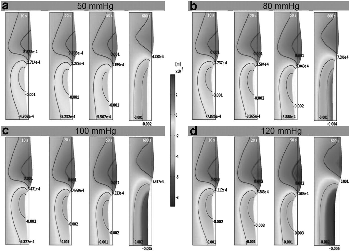
Dependence of the tissue radial displacement on a position within the simulated piece of tissue obtained for different pressures applied in the chamber: 50 mmHg
Quantitatively comparing, one can notice that the decrease of radius of tissue under the chamber for time 50 sec amounted approximately to 2 mm for pressure 50 mmHg and to 4.7 mm for 120 mmHg. The maximum increase of radius of the tissue for the same time was about 1.5 mm for the load 50 mmHg and 3.7 mm for 120 mmHg. It should, however, be underlined that the long time values of tissues displacement were strongly dependent on the assumed elastic parameters.
Parametric studies
The relative significance and time dependence of the mechanical and hydraulic mechanisms of pressure dissipation and deformation of tissue under the influence of mechanical loads are influenced by elastic properties and permeability of tissue, as well as on geometry of the considered system. In order to illustrate the interdependencies, Figure 6 shows results of parametric studies of pressure evolution in interstitial fluid at the control points G and F for three different values of Young's modulus E, Poisson's number ν, permeability K, and tissue thickness d. The central values of the parameters are identical with data presented in Table 1. Since the knowledge concerning properties of subcutaneous tissue is very limited, we postulate a moderate variations of the studied parameters. For each case, we assume that the pressure in chamber amounts to 120 mmHg and the parameters, the role of which is not being studied, are identical with the data given in Table 1. The results show that the material properties of tissue have significant influence on pressure dissipation, particularly for long time periods. However, taking into account that the typical time units of tissue treatment by a single chamber of pneumatic compression system amount to around 50 sec, the observed pressure changes are no larger than 30%. The dependence of pore pressure on tissue thickness is negligible.
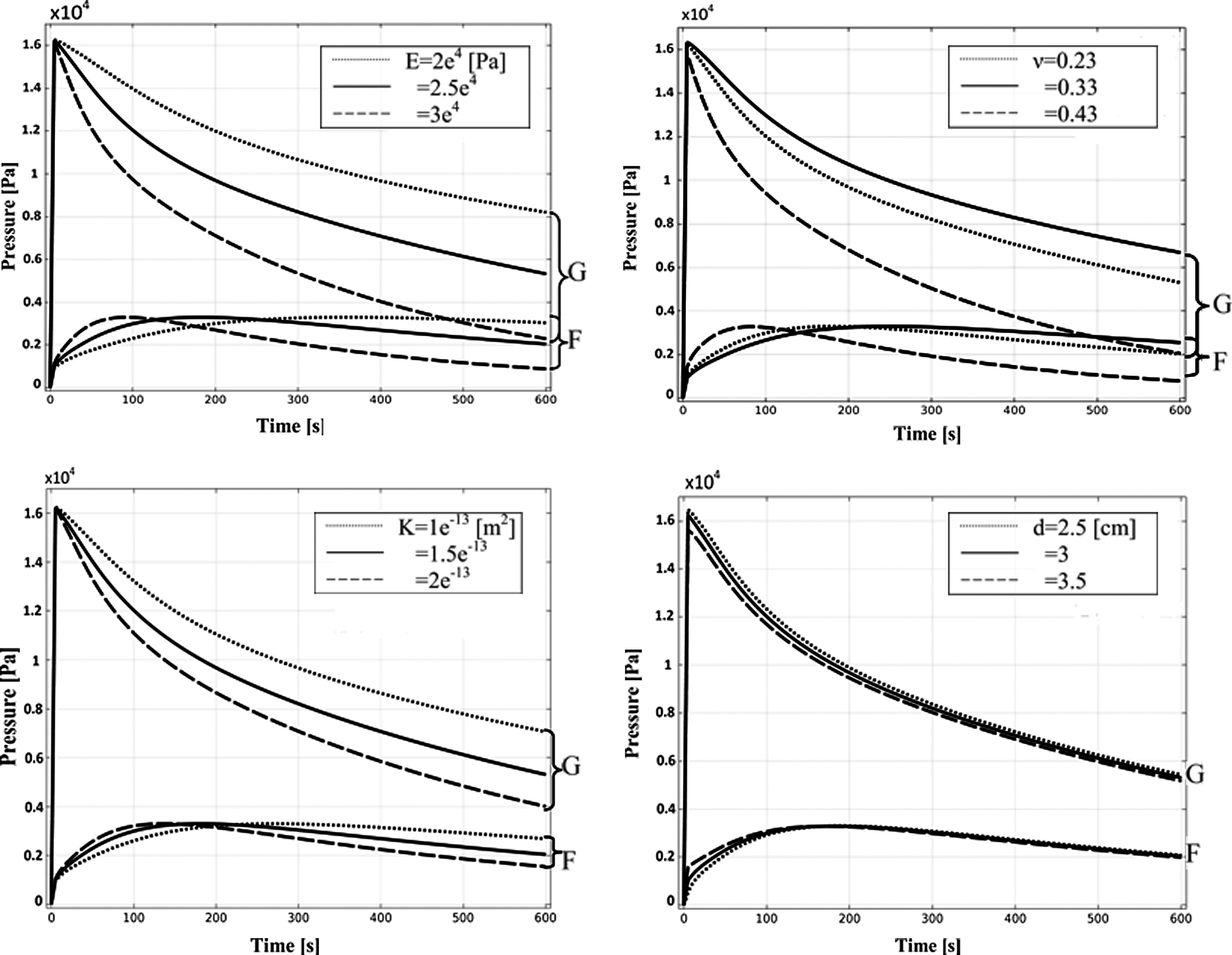
Parametric study of the elastic parameters Young's modulus E and Poisson's ratioν, permeability K, and thickness of soft tissue d on the evolution of pressure in tissue fluid at control points G and F.
Discussion and Conclusions
This article presents results of the hydro-mechanical simulations in a part of limb under the action of pressure in a single not moving chamber of sleeve for pneumatic compression. Parameters assumed for simulation were obtained from our studies in patients. 1
In the simulation model, the increase of pressure in the chamber induced both an increase of interstitial (pore) fluid pressure and velocity, as well as tissue displacement. The increment of the load from 50 to 120 mmHg did not guarantee squeezing out fluid from the tissue within 50 sec. The maximum pore fluid velocity was reached after 160 sec from the loading application. For the considered properties of the tissue, the squeezing out of the fluid was not terminated. The termination time point was full pressure dissipation.
In order to achieve this state, an appropriately long period of time seems to be necessary. The observations of predictions of pore fluid pressure at the control point located in the middle plane of the chamber (point G) showed that the pressure drop within 50 sec was less than 30% of its maximum value. This meant that further outflow of fluid from tissue under the chamber would take place when the pressure in the chamber was maintained longer.
The pressure evolution was quite different at the second control point (F), which was located in the tissue not loaded by the chamber. The pressure at this point assumed relatively low values in the considered time period, increasing, and then slowly decreasing.
The obtained results are addressed to a typical or average properties of tissues. In lymphedema treatment, a patient-specific approach is necessary and this should be the next step to optimize the parameters of compression. The parametric studies performed in the study indicate that both stiffness (represented by Young modulus and Poisson's ratio) and hydraulic conductivity of tissue play crucial role for effectiveness of tissue fluid pressure dissipation. However, the selection of the method of compression and its parameters cannot rest on purely hydro-mechanical data but should take into account biological factors corresponding to a particular disease state.
The adopted poroelastic model of the considered lymphedematous tissue assumed constant permeability, independently of tissue deformation and constant elastic parameters. If one considers intuitively decrease of permeability in the region of compressed tissue (negative dilatation) and corresponding increase of permeability in the region of expanded tissue, the changes of the poroelastic model predictions should be expected. For example, the important consequence of changes in the permeability would be slowing of fluid squeezing from the tissue under the chamber. The analysis of radial displacements (Fig. 5) and quantitative results for tissue dilatation (data not shown) suggest that, for the considered form of load of tissue by constant stress (pressure in the chamber), the decrease of permeability in compressed tissue may cause closure of fluid in tissue under the central part of the chamber. The confirmation of the hypothesis (e.g., by experiments) would require optimization of the chamber construction so as to avoid this effect. It seems to be possible by appropriate shaping of the chamber to result in proper distribution of deformation of the tissue.
Taken together, the poroelastic model has appeared to be useful for obtaining basic observations on the hydro-mechanical behavior of soft tissue under the load induced by pneumatic compression. The simulation showed that values of loads and time applied in the currently applied pneumatic compression systems are not sufficient to force complete outflow of fluid and pressure dissipation in the tissue. Further simulations taking into account multichamber sleeve and realistic tissue properties should deliver knowledge that allows optimization of the massage devices.
The results obtained do not refer to massage therapy realized by hand or other moving objects, where additional factors associated with formation and displacement of a fold in front of the moving object (like a bow wave) must be taken into account.
Footnotes
Author Disclosure Statement
No competing financial interests exist. This work was partially supported by the National Science Centre in Poland under Grant UMO-2011/01/B/ST8/07283 and the National Center for Research and Development NR13002606.