
Abstract
Cavitation was investigated as a possible damage mechanism for war-related traumatic brain injury (TBI) due to an improvised explosive device (IED) blast. When a frontal blast wave encounters the head, a shock wave is transmitted through the skull, cerebrospinal fluid (CSF), and tissue, causing negative pressure at the contrecoup that may result in cavitation. Numerical simulations and shock tube experiments were conducted to determine the possibility of cranial cavitation from realistic IED non-impact blast loading. Simplified surrogate models of the head consisted of a transparent polycarbonate ellipsoid. The first series of tests in the 18-inch-diameter shock tube were conducted on an ellipsoid filled with degassed water to simulate CSF and tissue. In the second series, Sylgard gel, surrounded by a layer of degassed water, was used to represent the tissue and CSF, respectively. Simulated blast overpressure in the shock tube tests ranged from a nominal 10–25 pounds per square inch gauge (psig; 69–170 kPa). Pressure in the simulated CSF was determined by Kulite thin line pressure sensors at the coup, center, and contrecoup positions. Using video taken at 10,000 frames/sec, we verified the presence of cavitation bubbles at the contrecoup in both ellipsoid models. In all tests, cavitation at the contrecoup was observed to coincide temporally with periods of negative pressure. Collapse of the cavitation bubbles caused by the surrounding pressure and elastic rebound of the skull resulted in significant pressure spikes in the simulated CSF. Numerical simulations using the DYSMAS hydrocode to predict onset of cavitation and pressure spikes during cavity collapse were in good agreement with the tests. The numerical simulations and experiments indicate that skull deformation is a significant factor causing cavitation. These results suggest that cavitation may be a damage mechanism contributing to TBI that requires future study.
Introduction
A
While most studies of TBI have focused on impacts to the head, this article discusses blast waves and their damaging effects. As IEDs have become more prevalent and blast injuries more common, a greater understanding of how shock waves interact with the human skull is required. More specifically, we will discuss cavitation as a possible damage mechanism causing TBI.
Cavitation occurs in many guises, but it always involves formation of bubbles in a fluid (Young, 1999). This article is concerned with the transient formation of bubbles in a low-pressure region of an unsteady fluid, often termed bulk cavitation. Bubbles form over a microsecond time interval, typically persist for tens of microseconds, and are on the order of a millimeter in diameter. Cavitation regions are the lowest-pressure regions in the flow. The surrounding higher-pressure fluid eventually collapses the cavitation region, generating a collapse shock that reloads the surrounding surfaces. During collapse, the individual bubbles also collapse, and in the presence of asymmetries such as a nearby surface, a bubble can deform into a torus, through which a high-speed fluid jet flows toward the surface (Young, 1999). This jet has a high enough velocity and pressure to damage the surface, an example being the pitting of a ship's propeller blades. The authors have simulated such a single-bubble event and computed pressures as high as 2900 psi.
Recently developed computational evidence suggests that extensive cavitation might occur in the cerebrospinal fluid (CSF) around the human brain due to explosive blast (Chafi et al., 2007; Moore et al., 2009; Moss et al., 2009; Nyein et al., 2010; Ziejewski et al., 2007). Non-impact blast is characterized by a rapid rise time to a peak overpressure (pressure above atmosphere), and an exponential decay followed by a prolonged negative underpressure (suction). The positive phase of the air blast overpressure shock wave passes through the front of the skull into the CSF and tissue that behave similarly to water. The impact of the shock wave in the CSF onto the skull at the contrecoup rapidly deforms the skull, thereby lowering the pressure to vapor pressure or less. A cloud of cavitation bubbles, often referred to as bulk cavitation, then forms in the CSF between the skull and brain tissue. Collapse of the cavitated volume, caused by the surrounding pressure field and elastic rebound of the skull, results in significant pressure spikes that may damage brain tissue.
Cavitation effects have been hypothesized as early as 1948 by Ward, and have since been investigated (Engin and Akkas, 1978; Gross, 1958; Hickling and Wenner, 1973; Lubock and Goldsmith, 1980; Suh, 1972), to name a few. Lubock and Goldsmith (1980), for example, studied the occurrence of cavitation in low-pressure zones using both simple spherical shells and cadaver skull replicas. When a spherical liquid-filled container simulating the head/brain was impacted on one side, it created a high pressure in the liquid on the impacted side. The transmission and reflection generated negative pressures at the contrecoup position on the side opposite the impact, resulting in cavitation. More recently, negative pressure from blast loading suggesting cavitation has been indicated (Chafi et al., 2007; Moore et al., 2009; Moss et al., 2009; Nyein et al., 2010; Ziejewski et al., 2007).
The cavitation damage mechanism has been observed in the widespread use of shock wave lithotripsy (SWL) for comminuting kidney stones. The collapse of cavitation bubbles is sufficient to pulverize kidney stones, and has also been associated with collateral kidney damage (Johnson and Young, 2006). Bailey and colleagues (2003) and Matsumoto and co-workers (2003) found that it is possible to focus the cavitation at the surface of the stone, pulverizing the material of the stone while reducing collateral damage. These studies tend to support the hypothesis that cavitation may be a damage mechanism contributing to TBI.
Methods
The Dynamic System Mechanics Advance Simulation (DYSMAS) Eulerian-Lagrangian code is used to study cavitation as a possible damage mechanism causing TBI. DYSMAS finite-element models were developed for the surrogate ellipsoidal heads simulating the cranium and brain as shown in Figure 1. The philosophy was to conduct analyses of simplified models that are quick-running to validate the cavitation model, and to assess the sensitivity of the head/brain response to various levels of blast overpressure. Initial work using this approach is discussed in Wardlaw and Goeller (2010).
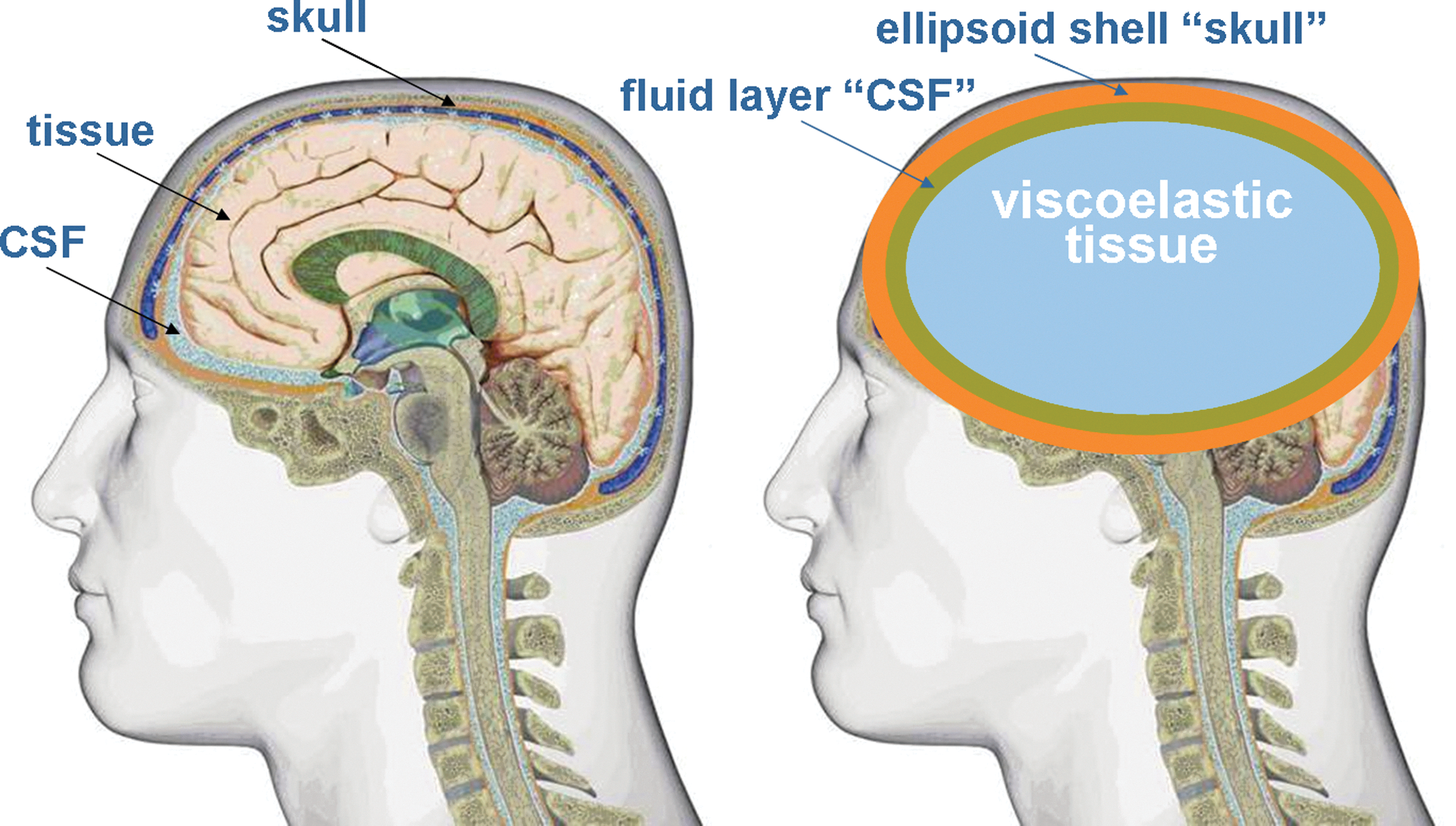
Surrogate ellipsoid model of the head/brain illustrating the elastic skull, simulated cerebrospinal fluid (CSF), and viscoelastic tissue.
Two configurations were investigated as shown in Figure 2; namely, simulating the tissue as a fluid (configuration no. 1), and simulating the tissue as a viscoelastic material surrounded by a layer of water simulating the CSF (configuration no. 2). Shock tube tests were conducted by Applied Research Associates (ARA) to provide data on pressure, strain, and acceleration, and to confirm the presence or absence of cavitation via high-speed video.

Illustration of two-dimensional surrogate ellipsoidal models with dimensions approximating a hybrid III male. Configuration no. 1 represents the cerebrospinal fluid (CSF) and tissue with water; configuration no. 2 replaces the tissue with viscoelastic material.
Ellipsoid head model computational simulation
A challenge in simulating blast loading of the head is accurately imposing the shock load on the head. This is accomplished with the DYSMAS code (Wardlaw et al., 2003), which is a coupled fluid-structure code. The DYSMAS program divides the simulation of blast loading to the head into two parts: Euler fluid and Lagrange solid. Each part is solved separately by programs that exchange information during execution and use the material properties shown in Table 1. For blast simulation of the head, the Euler fluid code models the initial explosion and shock transmission through the air to the head. The shock load is transmitted to the skull, which is modeled as a solid by the Lagrange code. The skull imposes shock loads on the CSF located inside the skull and modeled as a fluid. The CSF layer transmits this shock throughout the CSF fluid and also imposes loads on adjacent brain tissue, which is modeled as a viscoelastic solid. Meanwhile, the air shock continues to travel about the head, coalescing at the back to provide a reverse load to the skull.
CSF, cerebrospinal fluid.
A modified form of the Tillotson equation of state (Fiessler, private communication, 1998) is used to model water:
where p is pressure, ρ is density, e is energy, and the remaining terms are constants. Their values are given in Table 2 in cgs units. The first set of terms in equation (1) is the Tillotson equation of state for water while the second term pcav enforces a cavitation lower pressure limit.
A unique capability of DYSMAS is the cavitation formation model. Cavitation induced by a blast to the head is assumed to be manifested as bubbly water (i.e., bulk cavitation), with the presence of bubbles allowing water to expand rapidly in regions of tension. Cavitation is modeled by imposing a pressure floor Pcav, which similarly allows water to expand quickly without any restraining tension. The pressure floor Pcav is usually set between vapor pressure and −100 kPa (tension). Cavitation collapse occurs when the surrounding high-pressure fluid flows into the cavitated volume, generating a shock wave that can reload adjacent material. This model has been successfully used to simulate internal and external cavitation in other scenarios (Wardlaw et al., 2002).
Shock tube blast simulation experiments
The ARA 18-inch-diameter shock tube is used to simulate realistic IED explosive charges with overpressures ranging from a nominal 10 pounds per square inch gauge (psig) to 25 psig, with a pulse duration of 2–4 msec. The basic shock tube design, shown in Figure 3, consists of a cylindrical tube with a driver section separated from the driven section by relatively thin diaphragms. A compressor is used to increase the pressure in the driver section until the diaphragms rupture. The unequal pressures between the driven section and driver section propel a shock wave down the length of the shock tube. At the opposite end, a test object and instrumentation are placed to measure the response to shock wave excitation. With this configuration, the pulse duration was nominally 2 msec. A second configuration of the shock tube included an expansion cone that increased the pulse duration from 2–4 msec. This large-diameter shock tube produces a near planar shock wave simulating a relatively large IED blast at long standoff. Figure 4 demonstrates that DYSMAS accurately predicts the shock tube waveform given the magnitude of the shock tube driver gas pressure.
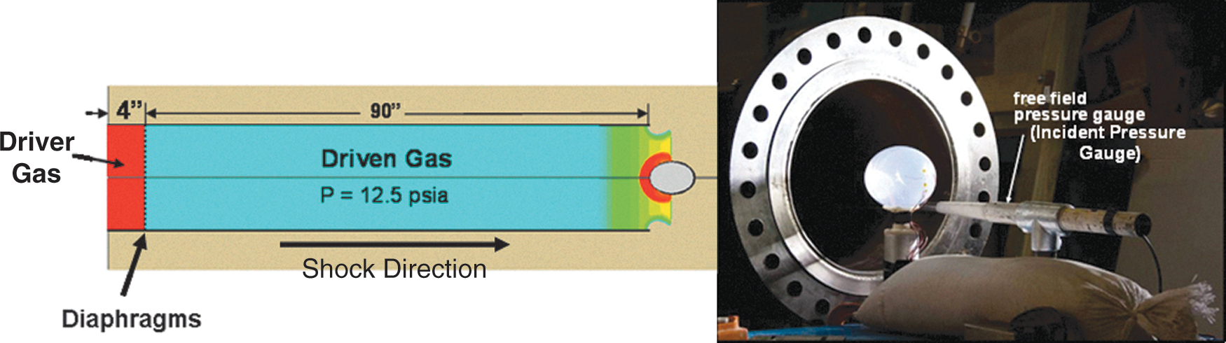
Illustration of the Applied Research Associates 18-inch-diameter shock tube, where the high-pressure driven gas creates a shock wave in the driven gas when the diaphragms are ruptured (psia, pounds per square inch absolute).
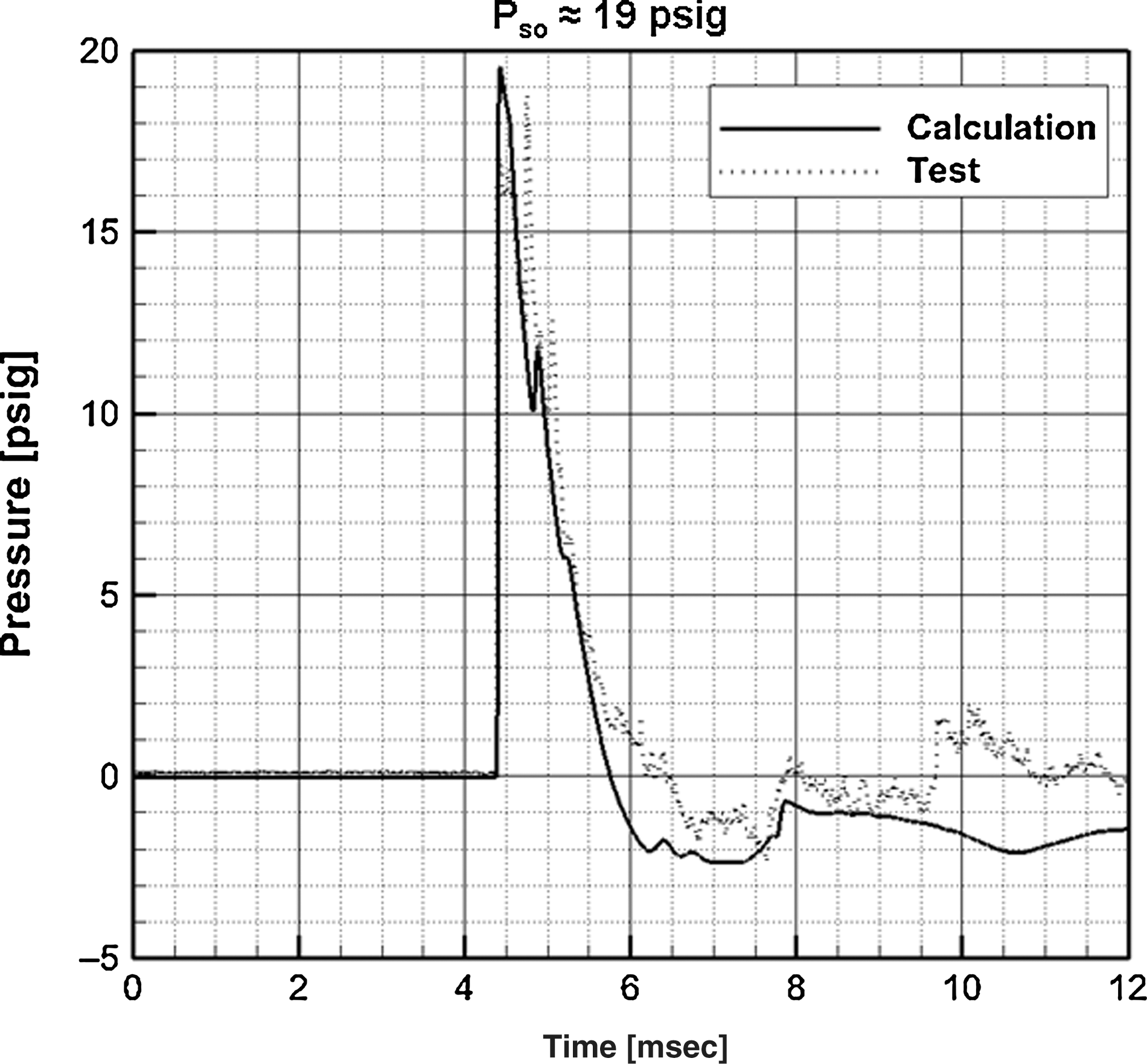
Comparison of the DYSMAS computed and measured pressure histories at the exit of the shock tube. The pressure waveform emulates that of an explosive blast (DYSMAS, Dynamic System Mechanics Advance Simulation; psig, pounds per square inch gauge).
Surrogate fluid-filled ellipsoid model
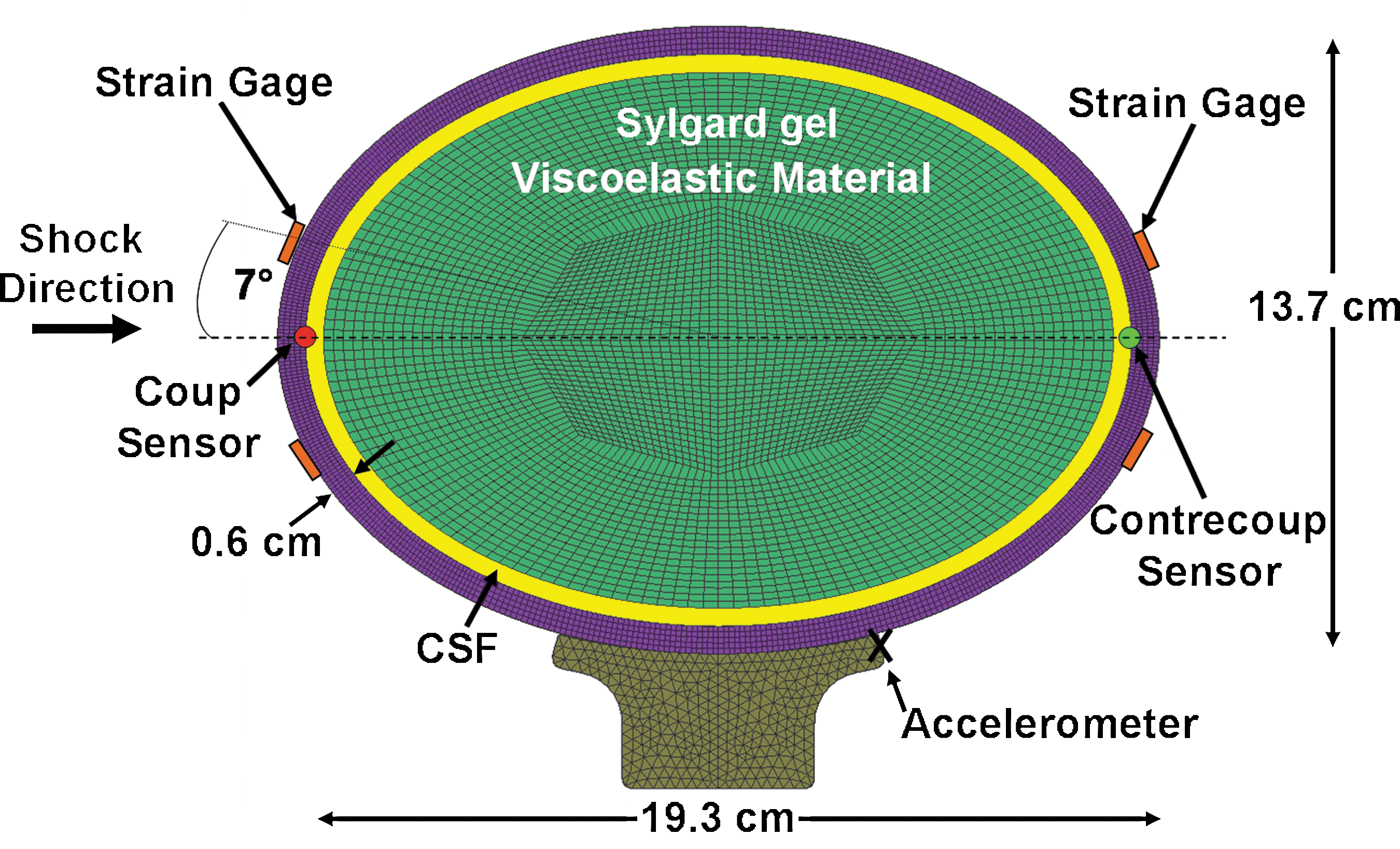
Since the brain is composed of about 77–78% water, simulation of a water-filled ellipsoid serves as a reasonable first step in studying cavitation. The ellipsoid, shown in Figure 5, was made of a transparent polycarbonate-like material with physical properties shown in Table 3. Two-piece construction using stereolithography was used to facilitate internal polishing and mounting of internal pressure sensors. Very small Kulite thin line sensors, model LL-072 and LL-080, were adhesively mounted on the inside surface at the coup and contrecoup positions to minimize invasive effects on shock wave propagation. A Kulite thin line pressure sensor was suspended at mid-length along the major axis to record pressure in the fluid. Pressure sensor data were filtered at 100 kHz to reduce noise. Precision strain gauges, model SGD-3/350-XY11, were mounted 7° off the major axis to record strain in the outer surface at the front and back of the ellipsoid. The ellipsoid was filled with vacuum-degassed distilled water and supported by rubber cylindrical tubes to simulate the neck. Neck properties, however, had little effect on the experimental results; during the 3-msec test time, the head did not move significantly.
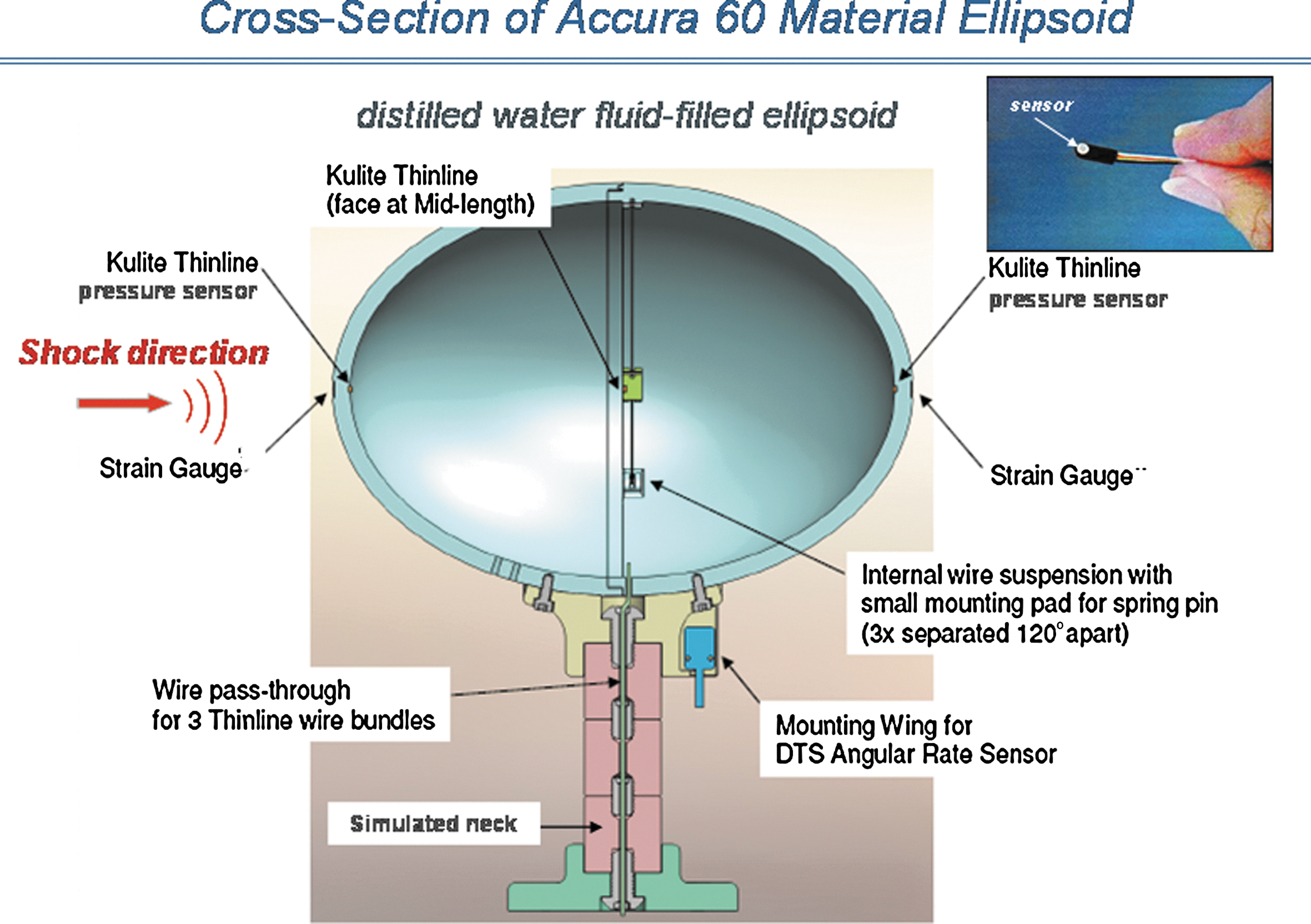
Cross-section of the transparent ellipsoid model showing the location of pressure sensors at the coup, mid-plane, and contrecoup positions. Strain gauges are located on the outer surface at the coup and contrecoup positions.
Surrogate Sylgard tissue ellipsoid model
The surrogate Sylgard ellipsoid head/brain is similar to configuration no. 1 shown in Figure 2, except a Sylgard gel was used to represent the tissue as shown in Figure 6. The CSF was modeled by a 4-mm-thick layer of degassed water surrounding the tissue.
DYSMAS hydrocode finite-element model of the skull and Sylgard gel simulant surrounded by a 4-mm-thick fluid layer, representing the cerebrospinal fluid (DYSMAS, Dynamic System Mechanics Advance Simulation).
The Sylgard gel 527 used to model the tissue was manufactured by Dow Corning. Numerous investigators have used silicone gels to mimic tissue in tests and analyses involving dynamic loading from blast (Alley et al., 2010; Gefen and Margulies, 2004; van den Bosch et al., 2000). The primary requirement for realistic transmittal of compressive pressure waves through the tissue is simulation of the density ρ, and bulk modulus K, that control wave speed c=(K/ρ)1/2 and impedance ρc. The compressive volumetric strain is also governed by the bulk modulus. Sylgard silicone gel and ballistic gels of various densities exhibit a bulk modulus of about 2.19 GPa, approximately the same as human brain tissue. A photograph of the ellipsoid in the ARA 18-inch-diameter shock tube is shown in Figure 7.
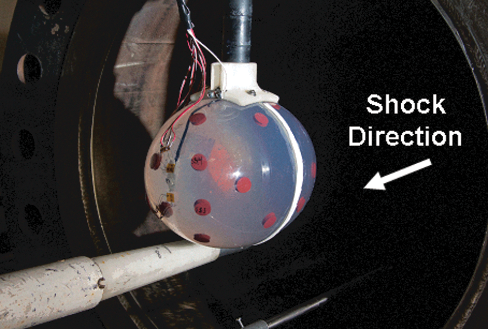
Upstream view of the Sylgard/cerebrospinal fluid ellipsoid and pressure sensor located at the exit of the shock tube.
The instrumentation used consisted of Kulite thin line (models LL-072 and LL-080) pressure sensors and strain gauges, thes same as those used in Series I with fluid tissue simulant. High-speed video (10,000 frames/sec) was used to photograph the inception of cavitation. The free field pressure was measured by a piezoelectric pencil gauge. An accelerometer on the top of the model neck was used to measure acceleration of the ellipsoid, from which velocity and displacement were obtained by numerical integration.
Results
Shock tube tests of fluid-filled ellipsoid model (Series I)
Seventeen shock tube tests have been completed, ranging from an overpressure of 7.4 psig to 23.9 psig. Based on pressure gauge and strain gauge results, there was an indication of cavitation in all tests. Figure 8a shows the 17.7-psig overpressure and internal pressures at the coup and contrecoup. Figure 8b shows the strain measured in orthogonal directions at the contrecoup. The pressure at the center (mid-length) was quite low and therefore is not shown.

Measured pressure history in the fluid-filled ellipsoid (
The pressure at the coup reaches a spike of about 100 psig, caused by the reflected shock wave, and then alternates with time. The pressure waves through the skull and tissue caused a negative pressure at the contrecoup of about −17 psig (−117 kPa), resulting in inception of cavitation at about 0.36 msec. Considering that the atmospheric pressure at the Denver test site is 12.5 psi, the absolute pressure is −4.5 psia, indicating the fluid is in tension. There is also an indication of periodic cavitation at later times caused by vibration of the skull. Cavitation was observed in the initial high-speed video, and found to coincide temporally with periods of negative contrecoup pressure. Initial collapse of the cavitated volume occurred at 0.8 msec, causing a peak pressure spike of about 210 psig (1450 kPa). The peak strain in the skull shown in Figure 8b occurs at the same time as the pressure spike, another indication of cavity collapse. Note also that the strain at the outside surface of the skull is negative (compressive) initially, indicating that the skull is deflecting inward at the time of inception of cavitation. This is consistent with our DYSMAS hydrocode calculations.
The repeatability of the general response is illustrated in Figure 9 for test 4 at an overpressure of 17.7 psig, and test 5 for an overpressure of 16.9 psig. The times and pressure magnitudes at inception of cavitation are in general agreement. The time of cavity collapse is repeatable even though the magnitude is lower in test 5.
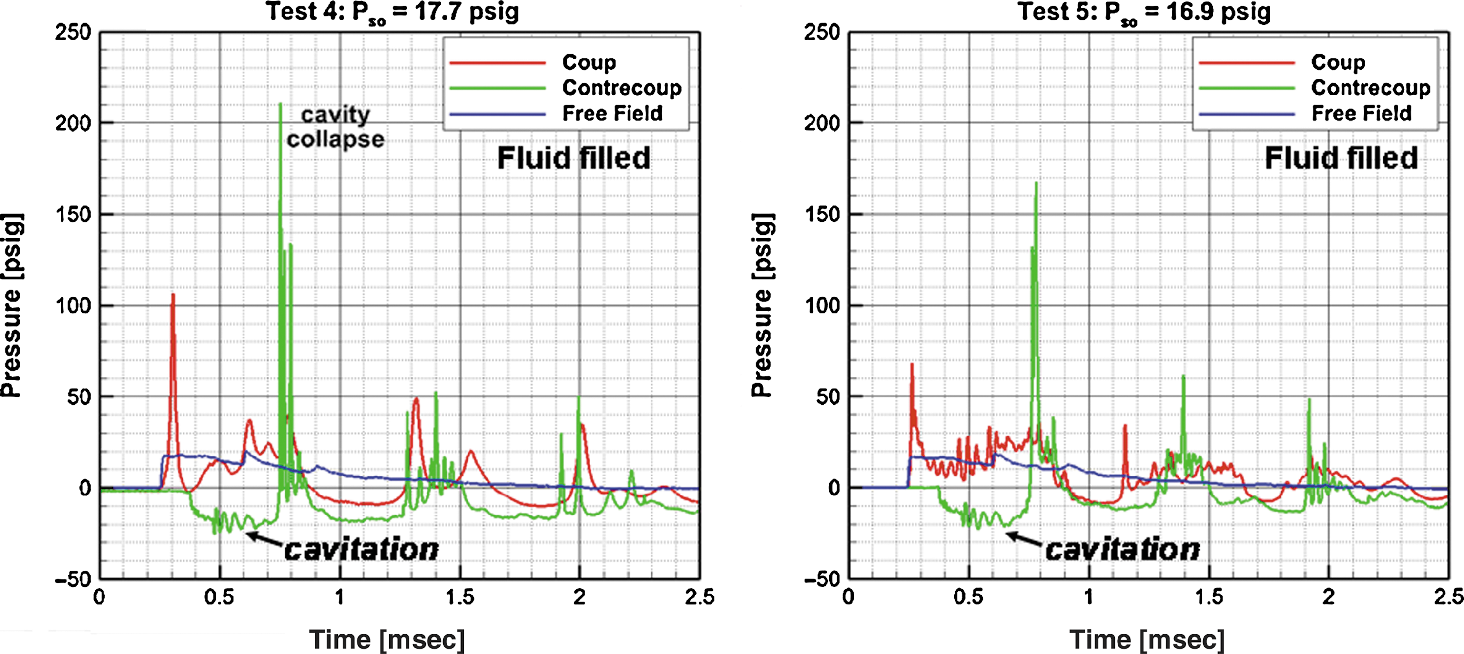
Comparison of measured pressure histories in the fluid-filled ellipsoid for test 4 at 17.7 psig overpressure, and test 5 at 16.9 psig (psig, pounds per square inch gauge).
One of the more interesting examples of cavitation that occurred at the contrecoup was in test 16 at 23.9 psig overpressure as shown in Figure 10. There were four observable sequences of inception of cavitation and cavity collapse visible in the film. Initially, individual bubbles varying in diameter from about 1 to 3 mm were observed. Individual bubbles were then seen to pulsate, eventually forming clusters (clouds) during the second inception of cavitation at 1273 μsec, and the fourth inception of cavitation at 2973 μsec. Unfortunately, the pressure sensor failed in this test, but the strain at the outer surface (contrecoup) reached about 600 microinch/inch during cavity collapse. This level is about as expected when compared to the 350 microinch/inch for 17.7 psig overpressure seen in test 4 (Figure 8b).
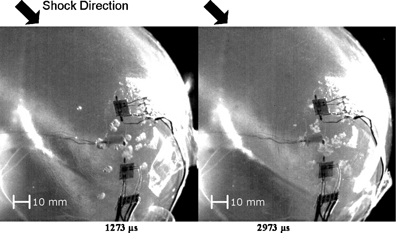
Photographs from test 16 at 23.9 psig overpressure, showing individual bubbles at contrecoup (1273 μsec, left), and clouds of bubbles at 2973 μsec (right; psig, pounds per square inch gauge).
Shock tube tests of Sylgard tissue ellipsoid (Series II)
There were 23 ARA Series II shock tube tests with overpressure from nominal 12 psig to 25 psig, and positive pulse duration of about 3 msec. Pressure-time responses at the contrecoup of the ellipsoid for air shocks of overpressure of 12.3 psig and 19.2 psig are shown in Figure 11. The results are similar to those for the liquid-filled ellipsoid, except that the magnitudes of the pressure spikes are lower. The internal shock waves through the skull, CSF, and Sylgard tissue caused a negative pressure of about −13 psig (−90 kPa), resulting in cavitation at the contrecoup at about 0.32 msec.

Measured pressure history in Sylgard gel ellipsoid at 12.3 psig (left) and 19.2 psig overpressure (right), showing inception of cavitation and the dependence of cavity collapse pressure spikes on overpressure (psig, pounds per square inch gauge).
The collapse of the cavitated volume caused an initial pressure spike of about 100 psig (690 kPa) at a shock overpressure of 19.2 psig, and 50–60 psig at an overpressure of 12.3 psig. Periodic deformation of the skull caused periodic cavitation and cavity collapse pressure spikes at the contrecoup. Cavitation bubbles were observed in the high-speed video during the periods of negative pressure. These results indicate no cavitation at the coup site, although the initial pressure of 55 psig at a shock overpressure of 19.2 psig from the reflected shock is approximately three times the incident pressure.
Computational modeling: Comparison with shock tube tests of the fluid-filled ellipsoid
DYSMAS is a coupled hydrocode that simulates both fluid and solid material in an interactive manner. It consists of GEMINI, which is a fluid solver, and Navy DYNA, which treats the solid. Navy DYNA is a derivative of the DYNA family of explicit finite element codes. Both codes run simultaneously during a simulation, exchanging information at the end of each computational time step.
DYSMAS was developed by a joint U.S./German agreement, under Office of Naval Research (ONR) sponsorship, to capture the fluid-structure interaction between underwater explosions and air-backed ship structures, including the effects of cavitation. The code is being used to identify, predict, and study cavitation and its effects within the brain due to transmitted blast from explosive loading. The computed pressure and strain histories were filtered with a 100-kHz low-pass filter, as was done with the experimental results.
A comparison of the DYSMAS hydrocode prediction of pressure at the contrecoup of the fluid-filled ellipsoid with an experiment for an overpressure of 16.9 psig is shown in Figure 12. The DYSMAS prediction of onset of cavitation at about 0.4 msec is in good agreement with the test. The predicted time of cavity collapse is also in good agreement. While the magnitude of the predicted cavity collapse pressure is lower than that of the experiment, Figure 12 demonstrates that cavitation does occur and can be predicted.

Comparison of predicted and measured histories at the fluid-filled ellipsoid contrecoup for an overpressure of 16.9 psig (psig, pounds per square inch gauge).
Computational modeling: Comparison with shock tube tests of the Sylgard tissue ellipsoid
The Sylgard gel ellipsoid model used in these tests was shown previously in Figure 6. Brain tissue, as well as gel, is distinguished from water in that they both support stress. A Zener linear elastic viscoelastic model was used in our FEM models to represent brain tissue and gel as described by:
where Go is the short-term shear modulus, G∞ is the long-term shear modulus, and β is the decay constant. The model accounts for elastic and viscous effects as depicted by a three-parameter Maxwell model. The shear moduli for tissue and Sylgard were estimated from vibration tests (Brands et al., 1999; Ziejewski et al., 2009). Figure 13 shows a fit to the data using the values of shear moduli indicated. A limitation of the three-parameter Maxwell model is that the dynamic modulus converges to the short time modulus at high frequency. In order to bound the analysis, we also modeled the viscoelastic effects using data by Gefen and Margulies (2004) as the lower bound, and data by Zhang (2004) as the upper bound, as shown in Table 4.

Shear modulus of Sylgard tissue versus frequency from Brands (1999), approximated by a three-parameter viscoelastic material model.
DYSMAS predictions in the fluid/Sylgard tissue ellipsoid are compared to test results in Figures 14, 15, and 16. These figures indicate that the DYSMAS hydrocode predictions are in good agreement with test results, and that the data for overpressure of 21.8 psig and 19.2 psig are nearly identical, suggesting that the tests are repeatable. Note also that the response waveform for the ellipsoid with Sylgard gel tissue is very similar to the water-filled ellipsoid model, although the gel simulant does appear to reduce the magnitude of the pressure spikes during cavity collapse.
Comparison of predicted and measured pressure histories at the contrecoup of the Sylgard tissue ellipsoid for 12.2 psig overpressure (psig, pounds per square inch gauge).
Comparison of predicted and measured pressure histories at the contrecoup of the Sylgard tissue ellipsoid compared to measured pressure for 21.8 psig overpressure (psig, pounds per square inch gauge).
Comparison of the predicted and measured pressure histories at the contrecoup of the Sylgard tissue ellipsoid for 19.2 psig overpressure (psig, pounds per square inch gauge).
In the simulation shown in Figure 17, the air shock with an overpressure of 19.2 psig moves along the center line of the ellipse and impacts the skull as shown in Figure 17a. This generates a reflected shock of three times the original magnitude and transmitted shock. The latter consists of two types: one through the CSF/tissue, and a second through the skull. Although the path around the skull is longer, its sound speed is higher and both shocks arrive at the contrecoup site at about the same time. This presses the skull inward, causing a negative pressure that initiates cavitation, which is visible as the white region at 0.49 msec shown in Figure 17b. Subsequent collapse of the cavitated volume causes a pressure spike at 0.7 msec as shown in Figure 16. Meanwhile, the air shock, traveling more slowly than either of the internal shocks, progresses towards the contrecoup site, enveloping the skull and compressing it towards the model centerline as it passes. When the air shock reaches the contrecoup site, it generates a high pressure and axial force at the back of the skull counter to that of the initial shock strike. The coup and contrecoup loads compress the skull, causing cavitation at the contrecoup (Figure 17c) at 1.14 msec. A cavity collapse pressure spike is then developed at about 1.4 msec, as previously shown in Figure 16.

Predicted pressure field development for the skull, fluid CSF, and viscoelastic tissue, from overpressure of 19.2 psig, showing (
In general, the DYSMAS hydrocode analyses and tests indicate that the mechanism for the onset of cavitation results from the compressive stress in the skull that deforms the skull/fluid interface at the contrecoup inward. This is confirmed by the compressive strain measurement at the outer surface of the skull indicating inward deformation. It is hypothesized that the fluid tends to separate from the skull when the inward skull velocity reverses direction due to elastic outward rebound (Wardlaw and Goeller, 2010). Inward inertia of the fluid lowers the pressure at the skull/fluid interface causing cavitation in the CSF. The pressure in the surrounding fluid causes the cavitated volume to collapse, resulting in high-pressure spikes in the CSF and on the inner surface of the simulated skull and tissue.
The predicted acceleration at the top of the neck was also in reasonably good agreement with test results as shown in Figure 18. The order of magnitude of 3500g occurred very early, caused by the rapid rise of the incident overpressure of 19.2 psig and the resulting reflected shock wave. Envelopment of the air blast wave around the ellipsoid, and the counterforce at the back of the ellipsoid, probably contributed to the relatively large negative acceleration (forward). The acceleration quickly dampened out after complete envelopment of the skull.

Comparison of predicted and measured longitudinal/acceleration at the neck for 19.2 psig overpressure (psig, pounds per square inch gauge).
Discussion and Summary
This article explores the hypothesis that blast alone may induce cavitation in the CSF, a possible TBI damage mechanism. The focus was on the development of numerical simulations and experimental shock tube tests to capture cavitation effects resulting from explosive blast trauma to the cranium. The 18-inch-diameter shock-tube test at ARA simulated a realistic IED blast overpressure profile, with a nominal peak pressure range from 10 psig to 25 psig, with positive phase pulse duration of 1–3 msec against ellipsoidal head/brain surrogate models. In Series I shock tube tests, the transparent ellipsoid was filled with degassed water to simulate the CSF and tissue. In Series II, the tissue was modeled by Sylgard silicone gel surrounded by a thin layer of degassed water to simulate the CSF.
The ellipsoids were instrumented with pressure sensors (Kulite LL-072) located at the coup, contrecoup, and center, inside the fluid. Strain gauges were mounted on the exterior for model verification. Through high-speed video of the shock tube tests, we verified the presence of cavitation bubbles in the CSF simulant at the contrecoup that coincided with periods of negative pressure. Changes in the bubble pattern (absence of bubbles indicative of bubble collapse) were accompanied by pressure spikes detected by the pressure sensors and strain gauges.
Inception of cavitation at the contrecoup was observed to occur at a negative pressure of about −100 kPa, which is in general agreement with findings of other investigators (Chafi et al., 2007; Lubock and Goldsmith, 1980). High-speed video indicated individual bubble diameters varying from 1–3 mm, converging to bubble clusters measuring 10 mm by 10 mm on a side. Past researchers (Brennen, 2001; Frost and Sturtevant, 1986) showed that the collapse of vapor bubbles emerge as a cloud of smaller bubbles rather than as a single bubble. This appears to be what is happening in the shock tube test of the fluid-filled ellipsoid at 23.9 psig shown in Figure 10. When the collapse occurs close to a solid plate, Benjamin and Ellis (1966) observed that jetting of the fluid (microjetting) occurs, which contributes to fracture of the bubbles into clouds of smaller bubbles. Collapse of these bubble clouds results in high-pressure spikes. In our experiments, pressure spikes up to 220 psig were measured due to the collapse of the bubbles from a nominal incident overpressure of 20 psig. Collapse pressure in the ellipsoid with Sylgard tissue was lower but still significant.
We could not positively identify cavitation at the coup site since the front of the ellipsoid was at the mouth of the shock tube, preventing high-speed video recording. However, we did measure negative pressure approaching ∼ 100 kPa at the coup in some tests, which is indicative of cavitation. At a nominal overpressure of 20 psig, we also measured a positive pressure on the order of 60 psig in the CSF at the coup caused by the normal reflected shock wave.
The DYSMAS hydrocode suite was used to develop finite-element models of ellipsoids including the skull as an elastic material, a water CSF layer, and viscoelastic material (gel) to represent the tissue. Models were validated by comparing simulated and measured internal pressures, external strains, and acceleration at the top of the neck. The predicted times of inception of cavitation were in good agreement with test results, as well as the times of cavity collapse. The predicted magnitude of pressure spikes from cavity collapse is also in general agreement with the measured values. However, it is recognized that due to the small length scale and short time scale of cavity collapse, it is likely that the actual pressures were significantly higher than those measured (i.e., the sensors measure average pressure over the crystal face filtered by the gage time constant). Numerical solutions (Hickling and Plesset, 1964) showed that the peak pressure in the vicinity of a collapsing spherical bubble in water reached 20 MPa (2900 psi) at a distance of twice the maximum bubble radius. In addition, we conducted a DYSMAS hydrocode simulation of a 2-mm-diameter bubble collapsing near a solid plate that showed a peak pressure of 20 MPa (2900 psi), caused primarily from microjetting of fluid onto the plate. Collapse onto a soft material (tissue) results in penetration of the water jet, possibly causing damage to tissue that is difficult to detect.
The DYSMAS modeling of the ellipsoid proved to be valuable in improving our understanding of blast-induced cavitation. Our experiments and numerical simulations show that skull deformation (flexure) is a major factor that contributes to the onset of cavitation and the resulting pressure spikes in the CSF from collapse of the cavitated volume. The role of skull deformation is consistent with the analyses of Moss and associates (2009), which showed that skull flexure produces most of the mechanical load in the brain from the blast simulations. The impact of the initial shock wave onto the front of the skull rapidly deforms the skull, causing a negative pressure at the contrecoup that results in cavitation in the CSF. Collapse of the cavitated volume induced by the surrounding pressure field, and elastic rebound of the skull, causes high-pressure spikes that might damage the brain tissue. Engulfment of the shock wave over the head causes a second shock wave at the back of the head comparable in magnitude to that at the front of the head. The interaction of these shock waves causes deformation of the ellipsoid skull that produces periodic cavitation and pressure spikes at the contrecoup for incident overpressure as low as 10 psig. The modeling and the experimental tests showed that cavitation was associated with the positive phase of the blast rather than the negative (suction) phase.
In order to obtain a transparent material for observing cavitation by video, we used a polycarbonate-like material in the ellipsoids with a modulus of nominally 3000 MPa. Ideally a skull modulus on the order of 6650 MPa (Gilchrist and O'Donoghue, 2000) is desired. We therefore conducted DYSMAS simulations of both ellipsoid models using moduli of 6650 MPa and 10,000 MPa, which showed similar predictions of onset of cavitation and cavity collapse pressure spikes.
The injury mechanism and criteria for non-impact blast-induced TBI injury is unknown. Data in the literature (Ward et al., 1980) suggest that serious brain injury occurs when the peak intracranial pressure exceeds 235 kPa (34 psi), with minor or no brain injury for intracranial pressure below 173 kPa (25 psi). The criterion was based on a combined analytical and animal experimental investigation of brain injury. Courtney and Courtney (2008) state that mild and moderate brain injuries occurred with local pressures in the range of 100–300 kPa (15–45 psi). The peak positive pressure spikes we predict, due to cavitation and cavity collapse, exceed all these values, but are generally of short duration (less than 0.5 msec). In general, the level of injury depends on pulse duration (impulse) in addition to pressure. Hence it is uncertain whether the peak pressure alone is injurious. Nonetheless, our research using a simple ellipsoid model suggests that cavitation may occur at operational IED blast overpressures. Thus cavitation may be a hidden damage mechanism contributing to TBI that requires additional research.
While the use of simple surrogate ellipsoidal models served as an informative first step in improving our understanding of the physics and role of cavitation in TBI, we plan to conduct simulation and testing of a more biofidelic representation of the head, including size, mass, geometry, and a Hybrid III biofidelic neck. Shock-tube tests will be conducted with and without the Advanced Combat Helmet (ACH) and pads to assess the effectiveness of the helmet and pads in minimizing or eliminating cavitation and its potentially damaging effects.
Footnotes
Acknowledgments
The authors would like to thank Dr. Judah Goldwasser, Program Manager, Defense Advanced Research Projects Agency/Defense Sciences Office (DARPA/DSO), for supporting this Small Business Innovation Research (SBIR) project. The effort depicted was also supported by the U.S. Army Research Office (ARO) under the direction of the Contracting Officer's Technical Representative (COTR), Dr. Ralph Anthenien. The authors would also like to acknowledge the advice and guidance provided by Col. Geoffrey Ling, DARPA, and Dr. Bruce LaMattina, formerly of the U.S. Army Research Office, and Dr. Michael Given of the Office of Naval Research (ONR).
The views expressed are those of the authors and do not reflect the official policy or position of the Department of Defense or the U.S. government. This is in accordance with DoDI 5230.29, January 8, 2009.
Author Disclosure Statement
No competing financial interests exist.