
Abstract
The potential of blast-induced traumatic brain injury from the mechanism of localized cavitation of the cerebrospinal fluid (CSF) is investigated. While the mechanism and criteria for non-impact blast-induced traumatic brain injury is still unknown, this study demonstrates that local cavitation in the CSF layer of the cranial volume could contribute to these injuries. The cranial contents of three post-mortem human subject (PMHS) heads were replaced with both a normal saline solution and a ballistic gel mixture with a simulated CSF layer. Each were instrumented with multiple pressure transducers and placed inside identical shock tubes at two different research facilities. Sensor data indicates that cavitation may have occurred in the PMHS models at pressure levels below those for a 50% risk of blast lung injury. This study points to skull flexion, the result of the shock wave on the front of the skull leading to a negative pressure in the contrecoup, as a possible mechanism that contributes to the onset of cavitation. Based on observation of intracranial pressure transducer data from the PMHS model, cavitation onset is thought to occur from approximately a 140 kPa head-on incident blast.
Introduction
T
Head impacts from falls or automobile collisions can induce large strains in the brain, causing bleeding and the familiar “coup-contrecoup” injuries to the brain. 4 –6 Impacts of lesser energies, such as those from boxing, football contact, or other contact sports, induce much smaller strains, but usually come in repeated measures so that a cumulative effect may come into play. 7 Other potential injury mechanisms have been studied over the last decade in an attempt to identify the mechanism associated with these small strains from fast events. 8,9 Candidate mechanism for blast-induced TBI include blood–brain barrier disruption, 10 referred mechanisms (including inflammation agents entering the bloodstream), 11,12 high arterial pulse pressure, 10 and a myriad of others. Each of these concepts remains a valid injury mechanism until proven otherwise, and up to now very few have been disproven. Included in these other possible mechanisms of injury are those that are not inertially-based but exist in the higher, energy-deposition environment. Of these, and supported by computational analyses, this study focuses on cavitation in the cerebrospinal fluid (CSF) surrounding the brain as a possible injury mechanism for blast-induced TBI. 13 –17
Cavitation is the formation of small bubbles in a liquid when pressure drops below the vapor pressure. 18 When pressure is restored, the bubbles collapse suddenly, producing a local shock wave that is capable of damaging nearby tissue and structures. Cavitation is a common process and commonly can be seen as pitting in spinning brass boat propellers, demonstrating the potential for damage in softer materials, such as brain.
Previous animal studies and computational models have demonstrated ample evidence that high-rate impacts and blast waves can produce significant cavitation from negative pressure at the contrecoup location. First hypothesized in 1948 by Ward and colleagues, 19 this concept has since been investigated by Gross (1958), 20 Suh and colleagues(1972), 21 Hickling and Wenner (1973), 22 Engin and Akkas (1978), 23 and Lubock and Goldsmith (1980), 24 as well as by others. Lubock and Goldsmith studied the occurrence of cavitation in low-pressure zones from direct impact using both simple spherical shells and cadaver skull replicas. 24 This study was one of the first to show the coup-contrecoup effect on an object that result in a low-pressure zone at the contrecoup. It is in this low pressure zone that cavitation pressures are possible. The collapse of such cavitation bubbles may cause significant damage during head injury. More recently, Ziejewski and colleagues (2007) demonstrated cavitation on a more sophisticated finite element model of the skull/CSF/brain. 25
Sotudeh-Chafi and colleagues (2007) used an Arbitrary Lagrangian Eulerian multi-material formulation for their study of blast induced TBI. 26 In one simulation, a 0.45 kg TNT explosive was detonated in close proximity to the head. The resulting contrecoup intracranial pressure produced a pressure of approximately −100 kPa. The research conclusion was that this could cause cavitation bubbles to form in the head and potentially damage brain tissue. Cavitation was not predicted for detonation of a 0.23 kg TNT charge in close proximity to the head, suggesting a threshold below which cavitation does not occur in their model.
The potential for cavitation damage has been observed in the widespread use of shock wave lithotripsy for comminuting of kidney stones. The collapse of cavitation bubbles is sufficient to pulverize kidney stones, and also has been associated with collateral kidney damage. Johnson and Young (2006) 27 investigated bubble creation, Rayleigh collapse of bubbles, and stone comminution both numerically and experimentally. In bubble collapse near a wall, they found that the presence of the bubble greatly amplified the pressure recorded at the stone interface. 27 Similarly, Bailey and colleagues (2003) 28 found that it is possible to focus the cavitation at the surface of the stone, pulverizing the material of the stone while reducing collateral damage.
Previous work by the authors used simplified transparent acrylic surrogate skulls in a step-wise approach to first visualize, then quantify, cavitation pressures inside the skull. 29 The first series of tests used two ellipsoid surrogates, one filled with degassed water and the other containing Sylgard silicone gel surrounded by a thin layer of degassed water, to represent the brain and CSF. A second series of tests sought to improve on the first by replacing the ellipsoid with an anthropomorphic skull surrogate. These tests used a 43.2 cm internal diameter shock tube to simulate a realistic improvised explosive device (IED) explosive charge (ranging from 69 to 172 kPa with pulse duration of 2 to 4 msec). Dynamic System Mechanics Advanced Simulation (DYSMAS) hydrocode simulations were made to replicate the testing. Through the use of high-speed video, dynamic pressure measurements, and DYSMAS simulations, the presence of cavitation bubbles in the CSF simulant was demonstrated.
In general, experimental testing and the DYSMAS hydrocode analyses indicate that the mechanism for onset of cavitation results from the compressive stress in the skull that deforms the skull/fluid interface at the posterior inward. 29 This skull motion is predicted through compressive strain measurements at the outer surface of the acrylic skull, indicating inward deformation. It is hypothesized that the fluid tends to separate from the skull when the inward skull velocity reverses direction due to elastic rebound outward. 30 Inward inertia of the fluid lowers the pressure at the skull/fluid interface, causing cavitation in the CSF. The pressure in the surrounding fluid causes the cavitated volume to collapse, resulting in high pressure spikes in the CSF and on the inner surface of the simulated skull and tissue.
These studies support the hypothesis that cavitation may be a damage mechanism contributing to TBI. However, there is still uncertainty, as other investigators such as Lindenburg and Freytag (1960) 31 and Edberg and colleagues (1963) 32 have noted brain damage from blows to the head occurring in regions of positive pressure only, and not in regions of negative pressure where cavitation might occur. 32,33 Nusholtz and colleagues (1996) 33 noted that although negative pressures were present during impact, they often were non-injurious. Nevertheless, medical analytical tools and mathematical modeling tools have improved considerably since these studies were conducted. We believe that the high incidence of TBI argues for a more thorough investigation of blast phenomena using the latest research technologies that will enable reconciliation of these apparently contradictory findings. Short of extensive focused testing on primate animal subjects, this study, characterized by progressive computational modeling validated by physical testing of man-made and biological surrogates, provides the best promise to deliver strong evidence regarding the potential of cavitation as a mechanism of non-impact blast-induced TBI.
This study builds on previous research that showed cavitation in a transparent head surrogate by testing instrumented post-mortem human subject (PMHS) heads in a shock tube, and attempting to identify the presence of cavitation through sensor data. Experimental pressure data is used to compare with the results of previous finite element modeling of the human head. While the presence of cavitation in a transparent head was observed, it does not have the transmissibility and damping characteristics of a PMHS head, so the likelihood that cavitation can occur for a survivable blast is investigated. The results will be compared with current injury thresholds for blast-induced lung and brain injuries.
Methods
Specimens
Three intact PMHS heads were used in the completion of this study (Table 1). All specimens were unembalmed, frozen post-mortem, and thawed for use. The target population was 50th percentile males with an upper age limit of 75 years. The cadaver specimens were screened for hepatitis A, B, and C, human immunodeficiency virus, and pre-existing pathology that may influence the response from a blast load. Pre-test radiographs and computed tomography (CT) scans were taken to verify that specimens with existing fractures or other trauma were excluded from this study. Test procedures were approved by the University of Virginia cadaver use committee, with final approvals from the U.S. Army Medical Research and Materiel Command Office of Research Protections (Log Number A-17344).
PMHS preparation and instrumentation
All specimens were kept frozen until needed, then thawed at room temperature conditions. The cervical spine from each specimen was dissected from the head at the occipital condyles, allowing the brain and dura mater to be removed. As the specimens used were frozen prior to testing, the brains became completely autolyzed when it became time to instrument. Since autolyzed brain did not represent the desired structure inside the cranium, it was determined that a more characterized replacement would be used, both for uniformity of test conditions as well as future finite element modeling of the tests. In preparation for the brain replacements, all remaining tissue and fluids were removed from the skull cavity prior to further instrumentation.
Pressure transducers and accelerometers were mounted across the human heads to capture the response of the head to blast (Table 2; Fig. 1). Two types of pressure transducers were mounted to the interior surface of the skull on dry tissue-free sections of bone using cyanoacrylate glue: the 1.4-mm thick Kulite Thinline (Model LL-1-080; Leonia, NJ), and the approximately 1.6-mm thick PCB Piezotronics (Model 138M156; Depew, NY). The PCB sensors are epoxy-sealed for use in conductive fluids, whereas the Kulite Thinline sensors are not. The Kulite sensors were treated with marine grade silicone sealant to prevent intrusion of the simulated CSF. Both types of gauges were prone to failure over time due to damage to leads or sensing element and intrusion of simulated CSF. Strain gauges—single axis gauges positioned laterally and sagittally—were positioned along the mid-sagittal line of the skulls with cyanoacrylate after careful reflection of the scalp and the removal of the periosteum.
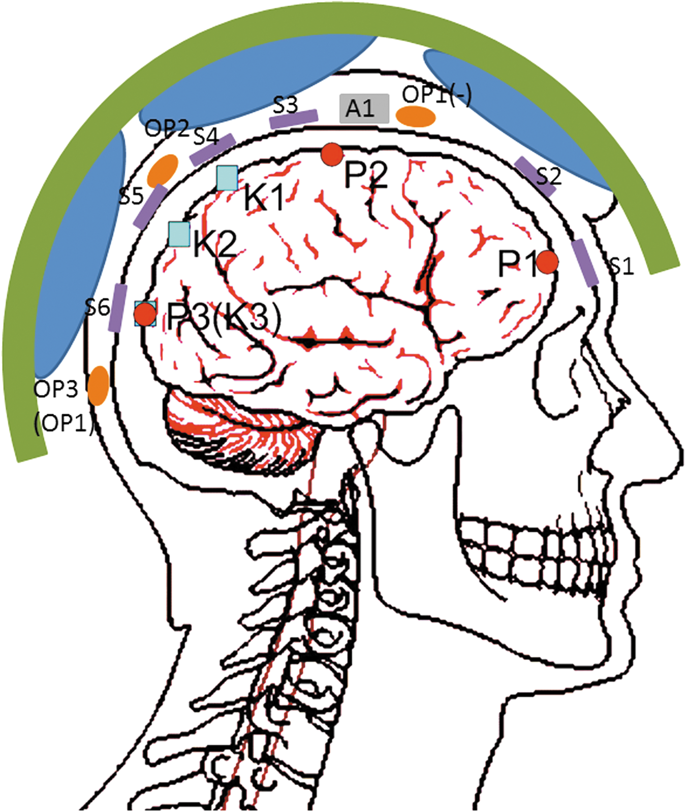
Instrumentation schematic of saline-filled post-mortem human subject specimen No. 1 (see Table 2). Alternate sensor locations for 20% gel-filled specimens No. 2 and 3 shown in parentheses. Color image is available online at
PMHS, post-mortem human subject.
An accelerometer cube was attached to the skull by a mating plate screwed directly into the skull at approximately the intersection of the mid-sagittal and mid-coronal planes. All pressure transducer leads were routed through the foramen magnum. The strain gauge leads were brought subcutaneously to the posterior region of the skull. A CT scan of each specimen was performed post-instrumentation to document the precise location of each gauge.
The data were recorded using meDAQs (Hi-Techniques, Madison, WI) sampling at 1 M Samples/s with 14 bits of resolution. The meDAQs have built-in bridge conditioning and an analog bandwidth of 100 kHz via an 8-pole Butterworth filter. Pressure data presented here was further filtered using a digital 40 kHz 8-pole Butterworth low-pass filter. Strain gauge data was filtered using a digital 10 kHz 8-pole Butterworth low-pass filter. All data channels were debiased based on a running average of pre-trigger data, and t = 0 sec (trigger) was taken as arrival time of the incident wave at the leading edge of the specimen.
For Test Series 1, a length of flexible tubing was inserted into the foramen to allow filling the brain cavity with simulated CSF (degassed normal saline) and to maintain the fluid level during testing. The saline solution level was maintained by an 18 cm pressure head in the reservoir. The foramen was sealed using polyester resin, and a mating plate attached to the base of the skull using self-tapping screws. This mating plate allowed the mounting of the specimen onto a 50% male Hybrid-III neck (Humanetics, Plymouth, MI). The specimen was then mounted into the shock tube, inverted and facing forward with the brain cavity filled with the saline solution as simulated CSF.
For Test Series 2, two PMHS specimens were filled with a 20% ballistic gel mixture to simulate the brain, surrounded by the saline solution to represent the CSF. This was achieved by inserting a latex sheath inside the skull large enough to conform to the inside surface of the skull. This sheath was then filled with the 20% ballistic gel mixture. After the gel had cured and lost some moisture content, sufficient space between the skull and the latex sheath was filled with the saline solution. The latex sheath prevented the ballistic gel from absorbing excess water from the simulated CSF during testing. The purpose of this construct was to create a more anatomically correct simulated brain/CSF system for the blast wave/cranium interaction. CSF layer thickness in the test specimens ranged from 2 mm along the base of the skull, to 8 mm at the crown, as measured by CT. As in Series 1 testing, the saline solution level was maintained by an 18 cm pressure head in the reservoir.
For this study, a 20% ballistic gel-filled skull was tested at 22°C. The 10% gel model commonly used as a brain simulant requires the test to be performed at 4°C to achieve the correct consistency, and therefore exhibits quite a stiff response. Since both the PMHS and the gel were to be tested at room temperature, a higher concentration was sought. Weighing the problems of material inhomogeneity 34,35 and the higher testing temperature, a 20% gel was determined to be ideal for this cavitation study. A representative surrogate in testing orientation inside the shock tube is shown in Figure 2.
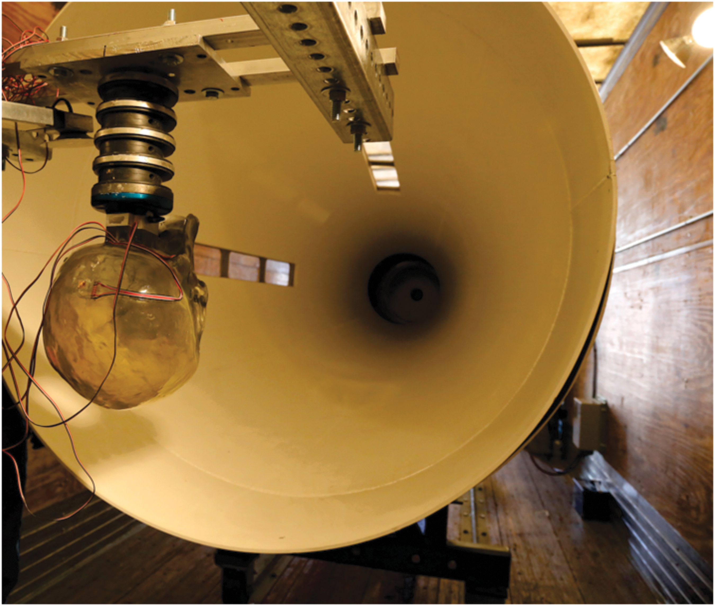
Photo of cephalus surrogate mounted inside the ARA Mobile Shock Tube. Color image is available online at
Shock tube
The shock tube testing of PMHS heads was conducted at two different facilities: the University of Colorado Medical School (Test Series 1, Denver, CO); and the United States Army Aeromedical Research Lab (USAARL; Test Series 2; Dothan, AL), with each facility using identical 457.2 mm shock tubes designed and fabricated by Applied Research Associates (ARA, Inc., Albuquerque, NM). The basic shock tube design consists of a cylindrical tube with a driver section separated from the driven section by thin diaphragms, as shown in Figure 3. The cylindrical driven section is followed by a conical section that expands the diameter so that the entire head and neck can fit inside without obstructing flow down the shock tube. Compressed air or helium is used to increase the pressure in the driver section until the diaphragm ruptures. The pressure difference between the driver and driven sections propels a shock wave down the length of the shock tube. The instrumented test specimen was placed at the opposite end to measure response to shock wave excitation. The driver section can be partially filled with inert spacers to change the effective driver length, and the membrane strength can be varied to change rupture pressure. The use of helium in the driver, with its higher acoustic velocity, results in a higher peak pressure and shorter duration. With the configuration shown in Figure 3, incident pressures as high as 480 kPa (70 psi) can be achieved with a pulse duration of 2 to 4 msec. The large diameter shock tube produces a near-planar shock wave, simulating the blast from 13.43 kg TNT at 4.5 m as shown in Figure 4. The pressure shown in Figure 4 was collected with the shock tube empty. Other incident pressure plots shown in this paper show an additional pressure rise caused by the reflection of the shock wave off the subject head. For comparing to existing blast lung tolerance curves, this overpressure would be equivalent to 50% survival for pulmonary injury. 36
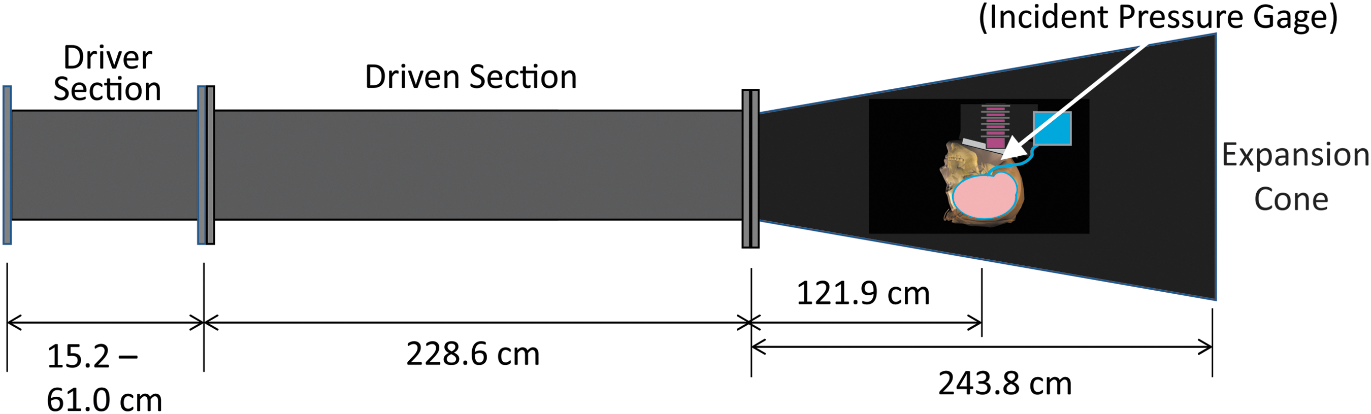
Shock tube schematic. Color image is available online at
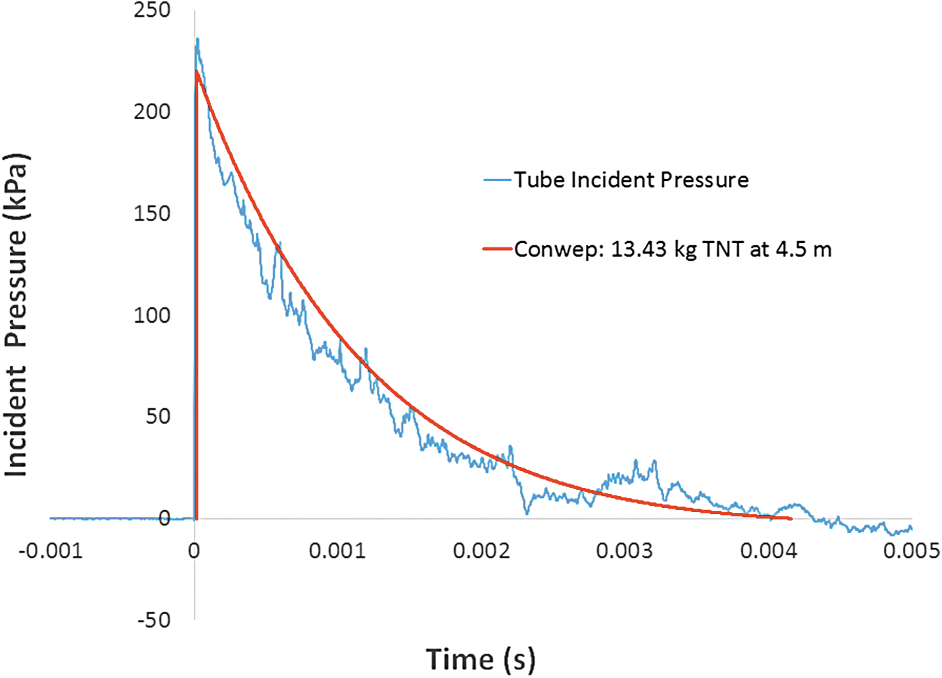
Predicted pressure waveform compared to test results from the shock tube with 1697 kPa air driver pressure. Color image is available online at
Loading conditions
A series of 13 tests were conducted at the University of Colorado Medical School on PMHS specimen No. 1 (the saline-filled specimen) with incident overpressures between 104.8 and 348.9 kPa (Table 3), both with and without a size large U.S. Army Advance Combat Helmet (ACH) on the specimen (Gentex Corporation, Simpson, PA). The size Large ACH was determined appropriate for the nominally 50% male specimens used in this test series. The helmet was outfitted with pads (rather than the suspension system), with all pads conforming to the outside of the specimens. A series of 14 tests were conducted at the U.S. Army Aeromedical Laboratory at Ft. Rucker, Alabama, on PMHS specimen No. 2 (the 20% ballistic gel/simulated CSF-filled specimen) with incident overpressure between 82.0 and 242.0 kPa (Table 4). Additionally, 10 tests were conducted on a second PMHS (Specimen No. 3) at Ft. Rucker, also using 20% gel/CSF brain surrogate (Table 5). These tests included incident overpressures between 80.7 and 254 kPa; however, pressure results were not usable due to sensor damage from previous specimen tests, although limited strain gauge data allowed some evidence of cavitation.
PMHS, post-mortem human subject; ID, identification; ACH, Advance Combat Helmet.
PMHS, post-mortem human subject; USAARL, United States Army Aeromedical Research Lab; ID, identification; ACH, Advance Combat Helmet.
PMHS, post-mortem human subject; USAARL, United States Army Aeromedical Research Lab; ID, identification; ACH, Advance Combat Helmet.
Results
DYSMAS results
Previous DYSMAS finite element analysis was used to guide the experimental testing in this study. 37 The DYSMAS Eulerian-Lagrangian coupled code was developed jointly by the U.S. Navy and the German government to accurately predict the response of a structure to explosive loading in either air or water. This embedded coupling in the DYSMAS code enables the analysis of highly dynamic fluid-structure interaction problems, such as cavitation and bubble collapse. DYSMAS has been validated against a range of structures including a full scale destroyer class ship exposed to underwater explosions that produced cavitation on the ship's hull. 38 DYSMAS has been adapted to the task of simulating the response of the human brain to air blast. Numerical simulations using DYSMAS predict the onset of cavitation and bubble collapse pressure spikes, and were in good agreement with tests of the transparent polycarbonate ellipsoids exposed to blast loads in the ARA shock tube. 29
The basic model was used to simulate the response of two test configurations of PMHS head specimens—namely, a PMHS specimen with brain removed and filled with degassed normal saline to represent CSF and tissue, and a PMHS specimen with brain replaced by 20% ballistic gel with a surrounding thin layer of degassed normal saline to mimic CSF. A sequence of time events for this DYSMAS model illustrating shock wave propagation through the head model filled with the 20% gel and thin CSF (saline) layer that predicted the onset of cavitation and a cavity collapse pressure spike is illustrated in Figure 5. Input is an incident overpressure of 186 kPa. The air blast strikes the head in frame “A” (0.125 msec), causing high pressure in the skull and tissue at the coup site. The shock wave propagates to the contrecoup in frame “B” (0.25 msec), and the rarefaction creates a negative pressure, resulting in a cavitated volume of bubbly fluid. The envelopment of surrounding positive pressure at the back of the head causes the cavitated volume to collapse in frame “C” (0.57 msec) resulting in a high pressure spike in the CSF and tissue as illustrated in frame “D” (0.775 msec). The resulting predicted shock at the back of the head is approximately 275 kPa. It is this pressure at the back of the head in combination with the frontal blast wave that is thought to exacerbate skull deformation resulting in periodic times of inception of cavitation and cavity collapse pressure spikes. This timing of events may explain why non-impact blast is different from blows to the head, and why blast may be more injurious. Experimental tests were designed around the modeled conditions, with the anticipation that cavitation could be detected.
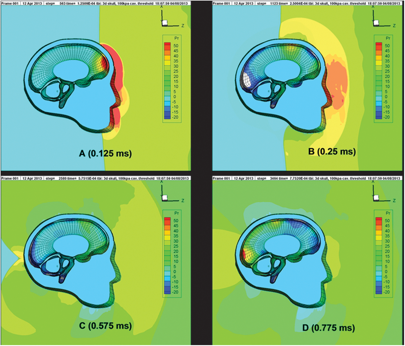
Sequence of wave propagation through simulated brain (run 3B) showing inception of cavitation B (0.25 msec) and cavity collapse D (0.775 msec), all units in kPa. Color image is available online at
Test Series 1: Intracranial pressure—saline
The incident shock tube pressure measurement for a test at overpressures of 146.2 kPa (Test 1-3) was compared with the measured intracranial pressures at the coup for a saline-filled cranium, as shown in Figure 6. The corresponding strains at location S1 (Fig. 1) shows local effects at the time of large pressure peaks (Fig. 6). For an incident shock wave of nominally 146.2 kPa and correcting for atmospheric pressure in Denver at the time (84.1 kPa), the reflected shock wave is 466.9 kPa (following the Rankine-Hugoniot relation). 39 The pressure measured at the internal coup (Sensor P1) with the degassed normal saline fluid was approximately 236 kPa, a pressure ratio of 0.50 with respect to the reflected tube pressure. For comparison, the incident shock tube pressure measurement for a test at overpressures of 169.6 kPa (Test 1-5) was compared with the measured intracranial pressures at the coup for a saline-filled cranium, as shown in Figure 7. Again, the corresponding strains at location S1 showed similar local effects at the time of large pressure peaks (Fig. 7) seen in Test 1-3. For an incident shock wave of nominally 169.6 kPa, and again correcting for atmospheric pressure in Denver at the time (84.1 kPa), the reflected shock wave is 566.8 kPa. 39 The pressure measured at the internal coup (Sensor P1) with the degassed normal saline fluid was approximately 379.0 kPa, a pressure ratio of 0.67 with respect to the reflected tube pressure.
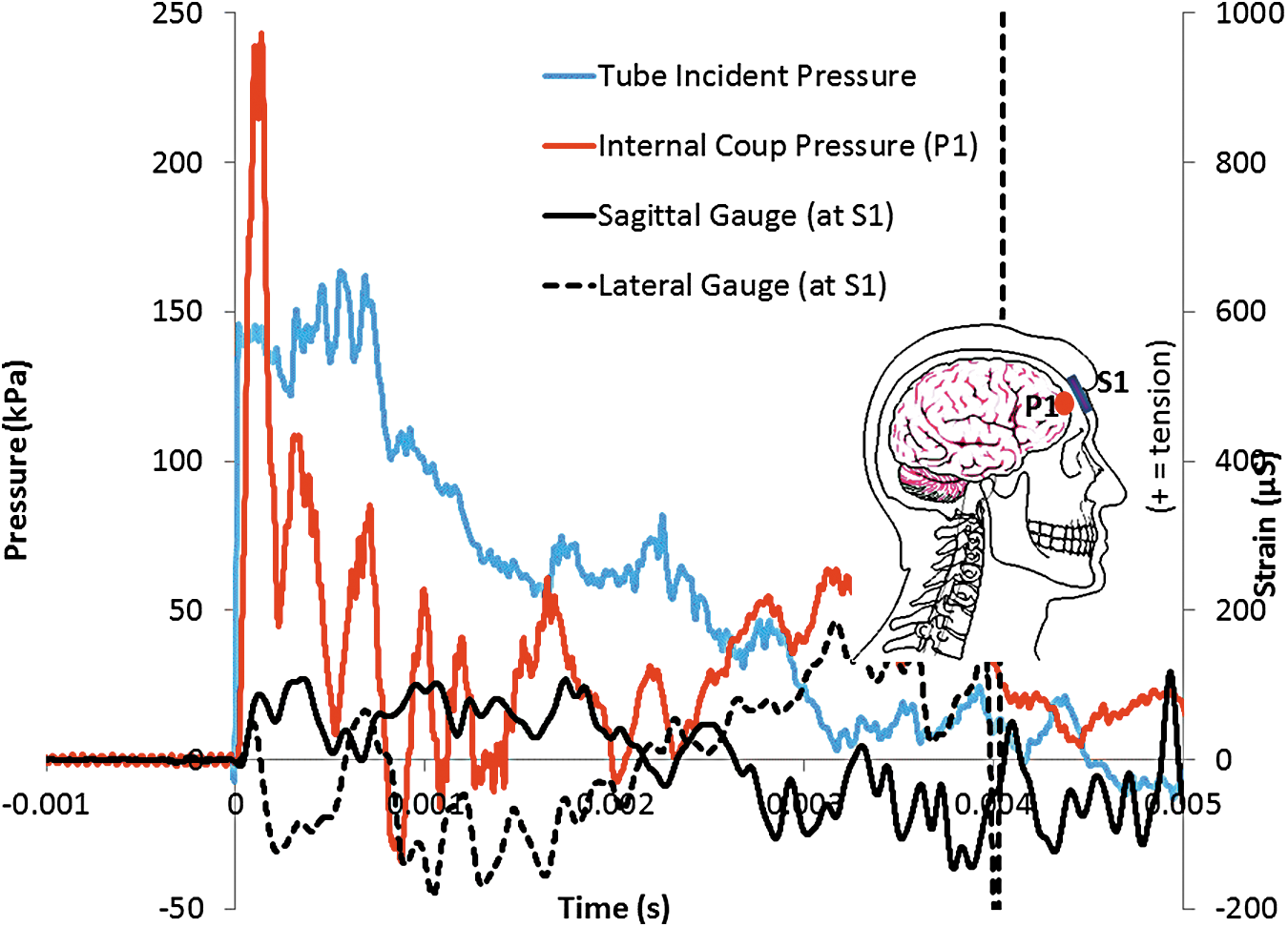
Pressure at coup (sensor P1), and Strains at coup (gauges S1 sagittal and lateral) for an incident overpressure pulse of 146.2 kPa (Test 1-3) for bare saline-filled post-mortem human subject head. (“+” strain = tension; “−“ strain = compression). Color image is available online at

Pressure at coup (sensor P1), and Strains at coup (gauges S1 sagittal and lateral) for an incident overpressure pulse of 169.6 kPa (Test 1-5) for bare saline-filled post-mortem human subject head. (“+” strain = tension; “−” strain = compression). Color image is available online at
The intracranial pressure traces at location of sensor K1 (Fig. 1), more superior than the contrecoup sensor, and the shock tube incident overpressure time-history of 160.6 kPa (Test 1-4) is shown in Figure 8. The internal crown pressure traces exhibit negative pressures in the range of approximately −100 to −150 kPa. Coupled with subsequent pressure spikes, this suggests the possibility of cavitation formation and collapse occurring during these tests. Analysis of the strains at the S4 location shows a large tensile peak at approximately 0.0005s, corresponding to the first negative pressure peak at the crown (Fig. 8). Similarly, the intracranial pressure traces at location of sensor K1 and the shock tube incident overpressure of 169.6 kPa (Test 1-5), is shown in Figure 9. The internal crown pressure traces exhibit negative pressures in the range of approximately −65 to −175 kPa. Coupled with multiple pressure spikes, this also suggests the possibility of cavitation formation and collapse occurring during these tests. Analysis of the strains at the S4 location shows a large tension/compression oscillation between approximately 0.0005 sec and 0.00075 sec, corresponding to the first negative/positive pressure oscillation at the crown (Fig. 9). Note that the compression strain S4 spike coincides with the positive pressure K1 spike at approximately 0.0005 sec that is an indication of bubble collapse from cavitation. Taking this data as evidence of possible cavitation, the next test series used ballistic gel-filled specimens with a thin layer of fluid to model the CSF surrounding the “brain.”
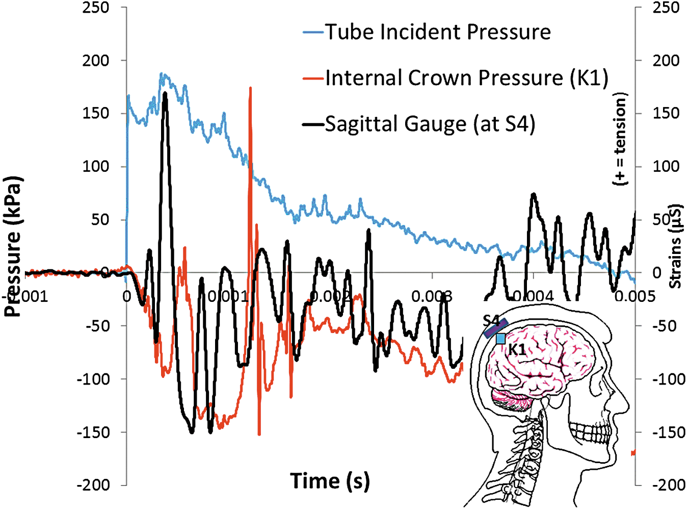
Internal pressure near crown (sensor K1), and Strains at crown (gauges S4 sagittal) for an incident overpressure pulse of 160.6 kPa (Test 1-4) for a saline-filled post-mortem human subject cranium. The negative pressure responses inside the skull suggest cavitation for a range of incident overpressures. (“+” strain = tension; “−” strain = compression). Color image is available online at
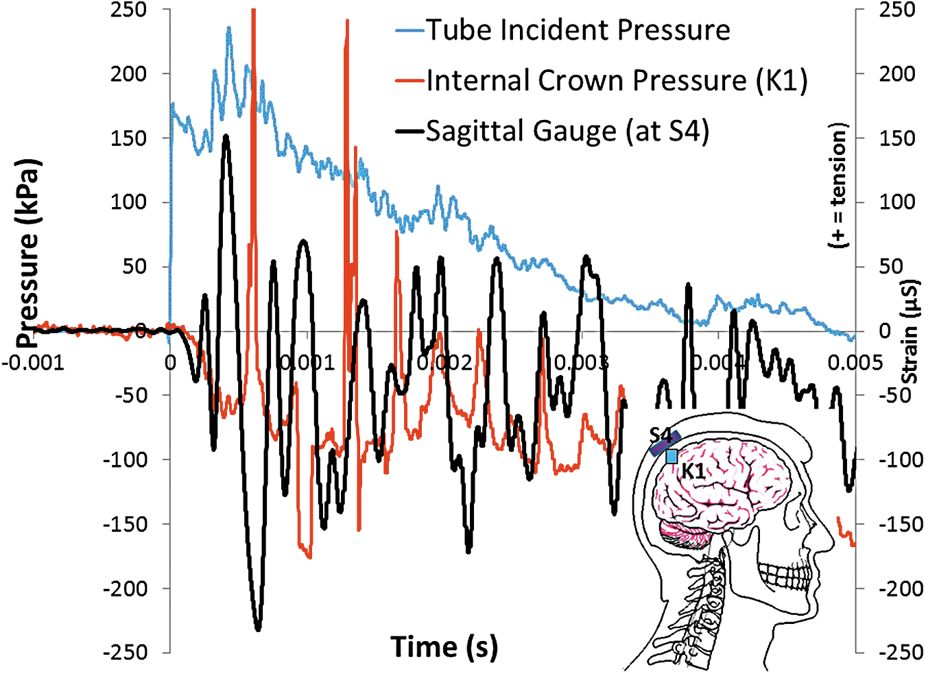
Internal pressure near crown (sensor K1), and Strains at crown (gauges S4 sagittal) for an incident overpressure pulse of 169.6 kPa (Test 1-5) for a saline-filled post-mortem human subject cranium. The negative pressure responses inside the skull suggest cavitation for a range of incident overpressures. (“+” strain = tension; “−” strain = compression). Color image is available online at
Test Series 2: Intracranial pressure—ballistic gel/saline CSF layer
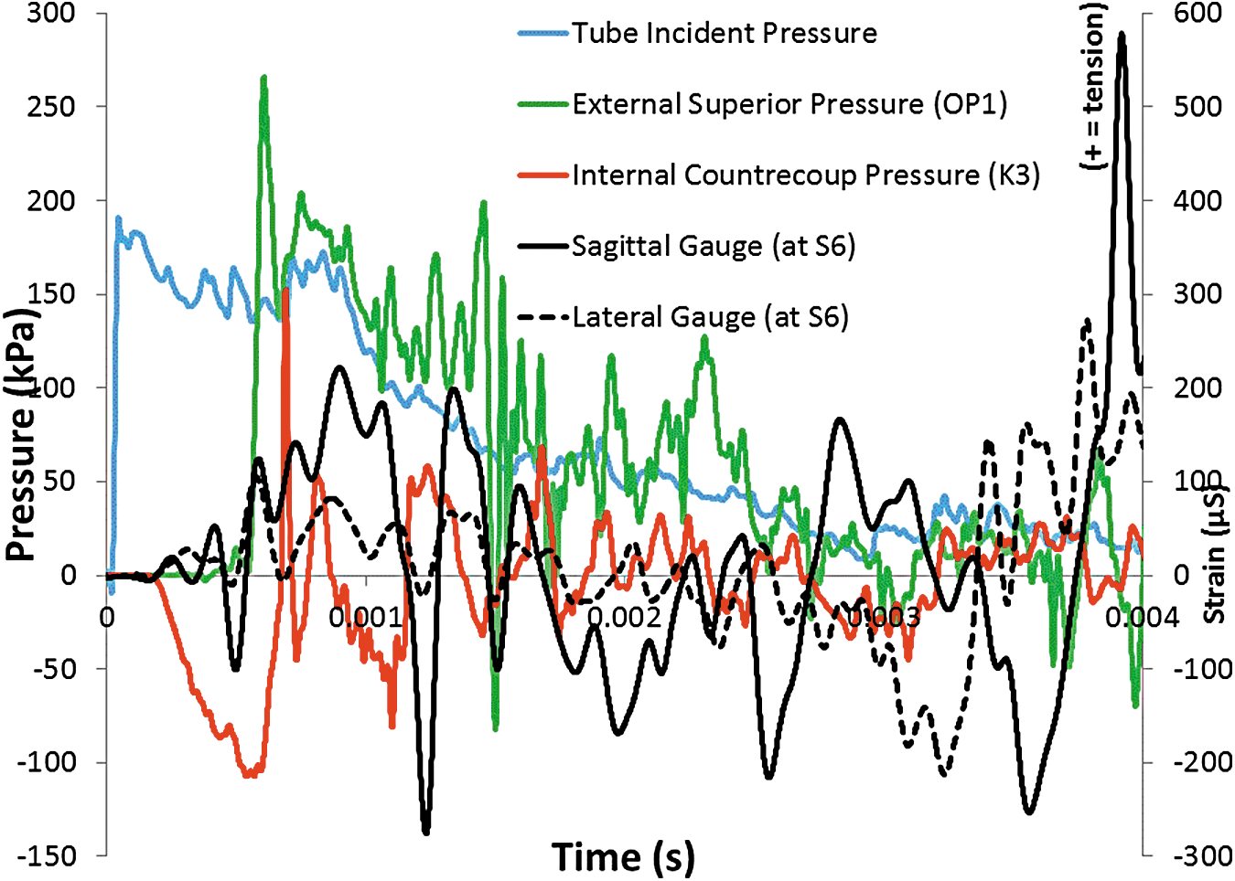
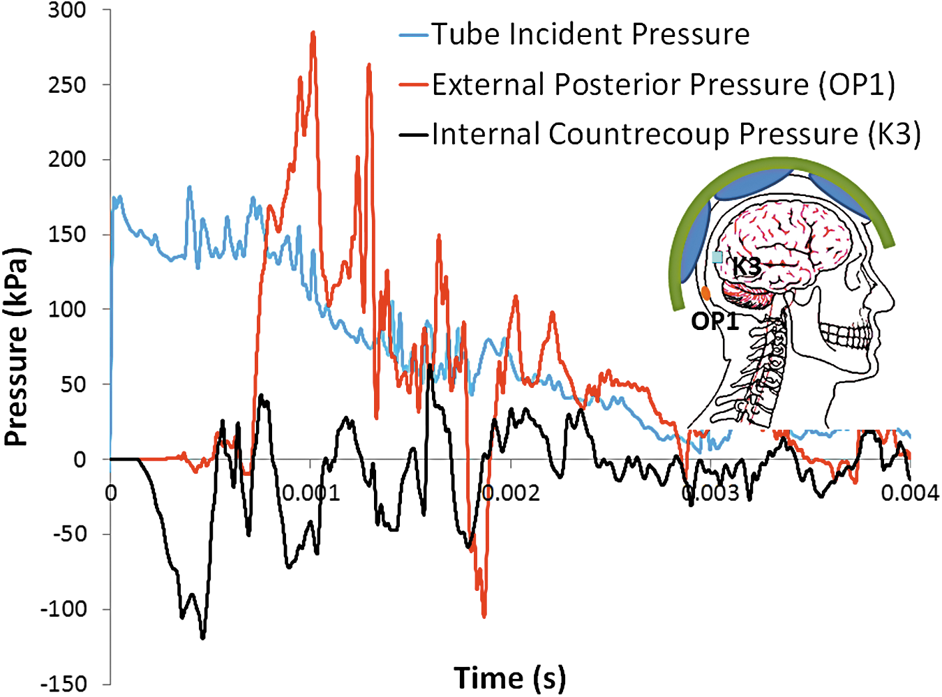
The intracranial pressure at the contrecoup (sensor K3; Fig. 1) is shown in Figure 10 (Test 2-1) and Figure 11 (Test 2-3) along with the external pressure at the posterior skull (OP1) and the incident wave. With a combination of ballistic gel and simulated CSF, the largest indication of cavitation occurs not at the crown sensor location as in the saline tests, but at the contrecoup. Note that internal pressure arrives at the contrecoup before the external pressure. Pressure at the external posterior skull is shown to determine the arrival time of the shockwave at the back of the head due to envelopment of the air blast wave. Initially the pressure-time waveforms of Test 2-1 and 2-3 are similar, with the larger overpressure of Test 2-3 leading to a more pronounced negative phase. For Test 2-3 (Fig. 11), there is a sharp negative-to-positive pressure spike seen in the internal countercoup pressure gauge, likely indicating cavitation in the saline near the transducer. The magnitude of the pressure spike from cavity collapse may have been higher if the pressure gauge was closer to the collapsing jet. Note that the probable cavitation collapse occurs after arrival of the shock wave at the back of the head.
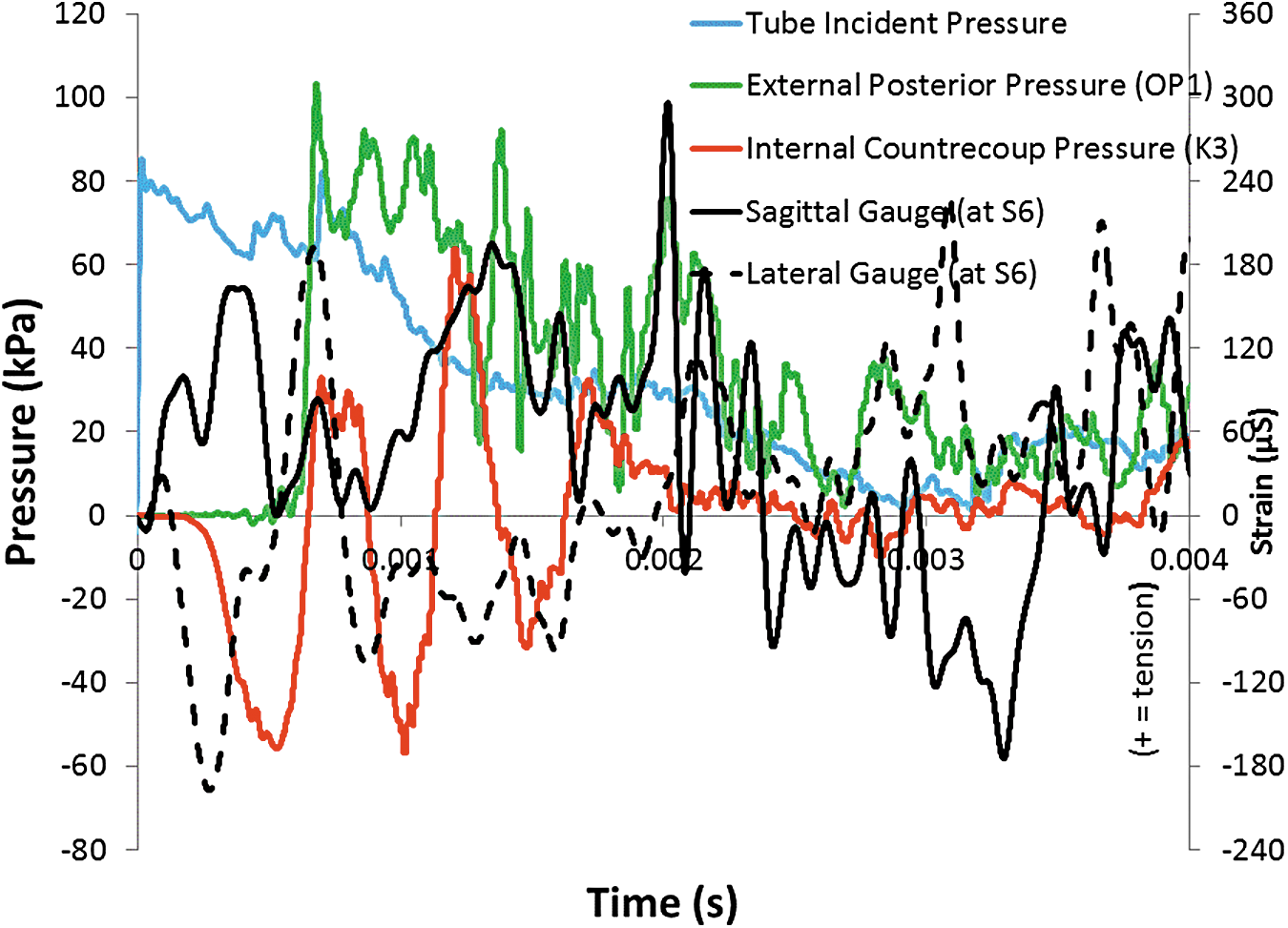
Pressure at contrecoup (sensor K3) as compared to external posterior (OP1) and incident wave, and Strains at contrecoup (gauges S6 sagittal and lateral) for bare gel-filled post-mortem human subject head for overpressure of 82.0 kPa (Test 2-1). (“+” strain = tension; “−” strain = compression). Color image is available online at
Pressure at contrecoup (sensor K3) as compared to external posterior (OP1) and incident wave, and Strains at contrecoup (gauges S6 sagittal and lateral) for bare gel-filled post-mortem human subject head for overpressure of 183.0 kPa (Test 2-3). (“+” strain = tension; “−” strain = compression). Color image is available online at
The sagittal and lateral strain gauges at location S6 (Tests 2-1 and 2-3) indicate a local deformation at the contrecoup that occurs before the external shockwave envelopes the head (OP1), and may be the result of high localized internal pressures or compression through the skull (Fig. 10 and Fig. 11). Similar tensile strains are seen in both Test 2-1 and 2-3 (Fig. 10 and Fig. 11), although the compression strains are not developed in 2-3 as compared to Test 2-1.
Repeatability of the intracranial response at the contrecoup is demonstrated in Figure 12 for Tests C2-3 and C2-5, both at a nominal overpressure of 190 kPa. Note that both tests exhibit high negative pressures at the internal contrecoup, followed by a sharp rise to high positive pressures. Again, this points to evidence of possible cavitation bubble formation and collapse.

Comparison of intracranial pressure at contrecoup for two tests with comparable incident pressures, 183.0 and 184.1 kPa (Tests 2-3 and 2-5, respectively) demonstrating test repeatability for a gel-filled post-mortem human subject head. Color image is available online at
In Test 3-4, sagittal strain gauges show the progression of strain along the midline of the head (Fig. 13). Note that compression strains align, with the largest strain (at A) indicating potential cavitation under Gauge S5. This large compressive strain indicates a large inward deflection of the skull at that location, similar to previous tests that also showed indications of the presence of cavitation at corresponding locations inside the head.
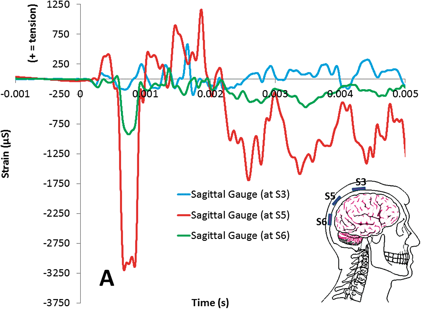
Strain Gauge data at locations S3, S5, and S6 for Test 3-4 (incident blast overpressure of 230.1 kPa). Note alignment of strains with peak positive (compression) strain occurring at Gauge S5 (Point A on the graph), indicating a possible cavitation event around this location. (“+” strain = tension; “−” strain = compression). Color image is available online at
Effect of ACH
The intracranial pressure at the coup of the saline-filled PMHS head, both without the ACH helmet (Test 1-4) and with the ACH helmet (Test 1-6), is shown in Figure 14A and 14B, respectively. This comparison indicates that the ACH helmet is effective in reducing the intracranial pressure at the coup by approximately 0.45.
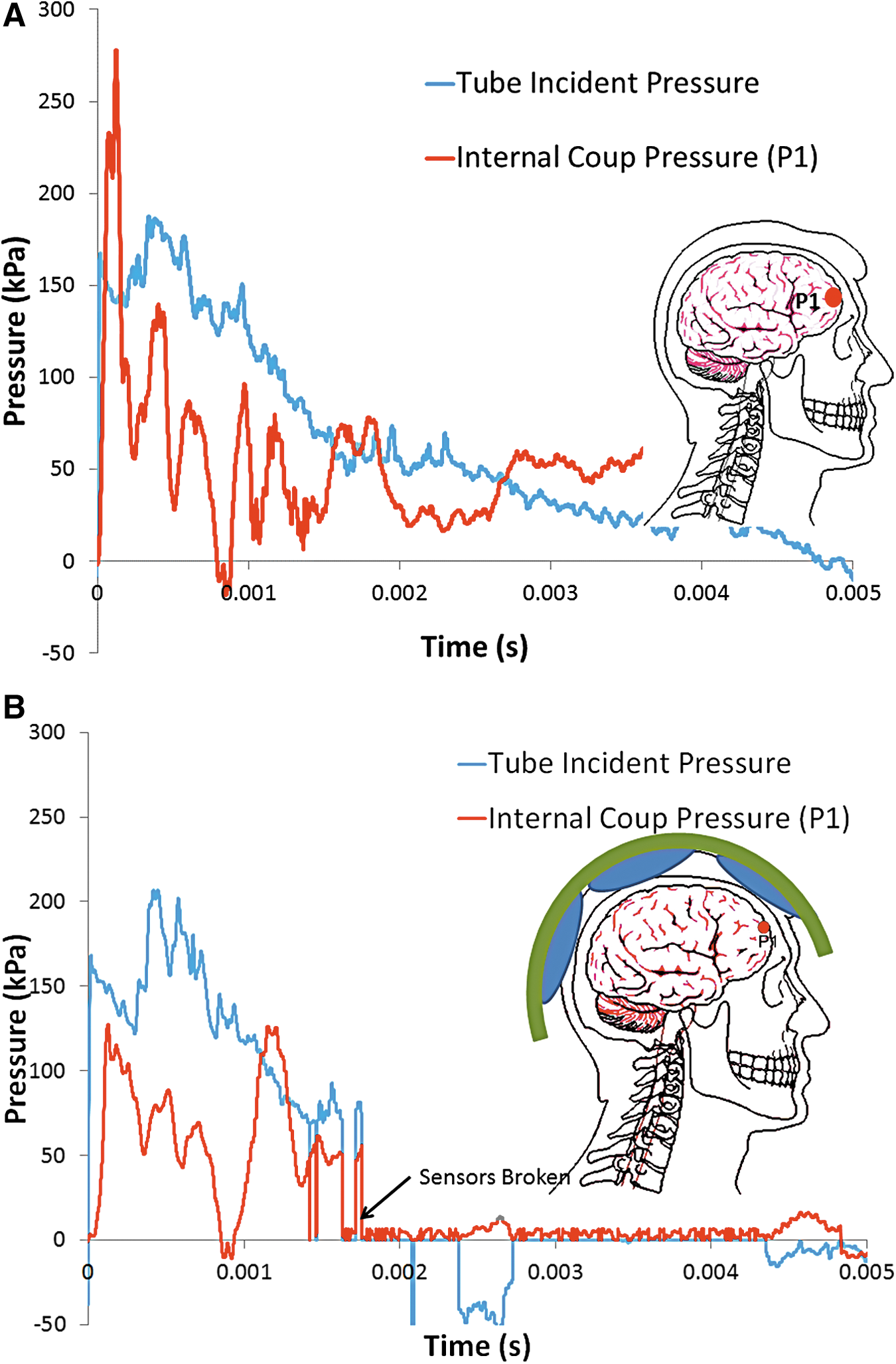
Pressure at coup (sensor P1), compared with incident pulse, in saline-filled post-mortem human subject head to blast overpressure of 160.6 kPa for
Similar effects of the ACH on internal pressures also were observed in the 20% gel/CSF head for similar incident blast pressures. Given that evidence of cavitation did occur at the internal contrecoup (positive pressure spikes of approximately 150 kPa) in both Tests 2-3 and 2-5 at an incident overpressure of approximately 190 kPa as indicated in Figure 12, the ACH again appears effective in reducing contrecoup pressure spikes (positive pressure spikes of approximately 25 kPa) as evident in Figure 15 (Test 2-6). Note that the ACH delays the arrival of the external shock at the back of the head (OP1), with this change in event timing perhaps contributing to the apparent protective nature of the ACH.
Intracranial pressure at contrecoup of gel-filled post-mortem human subject cranium with Advance Combat Helmet (ACH) at nominal overpressure of 177.2 kPa face-on blast demonstrating the ACH eliminating the pressure spike (Test 2-6). Color image is available online at
Discussion
The feasibility of cavitation as a possible damage mechanism of traumatic brain injury during a blast event was investigated. As a blast wave enters the head, a pressure wave is transmitted through the scalp, skull, CSF, and tissue, resulting in one or more regions of negative pressure that may result in cavitation and subsequent damage to the brain. Specific aims of the research included improved fidelity of mathematical modeling and material characterization to predict inception of cavitation to prevent the inception of cavitation and its effects, validate the modeling with shock tube testing of PMHS heads, and identify if injury mitigation is feasible.
A stepwise approach was utilized beginning with a simplified transparent two-dimensional ellipsoidal model of the human head to develop an understanding of the basic physics of cavitation in the brain. 29,30 Next, a more complex three-dimensional surrogate, consisting of a transparent skull constructed to represent the 50th percentile male, was tested along with PMHS cadaver heads with simulated properties of the brain tissue and CSF. Validation of the numerical models was performed using shock tube experimental data involving increasing complexity of materials, hydrodynamics, and mechanical aspects.
Previous shock tube tests of both the transparent ellipsoidal and 50th percentile skull surrogate were conducted using the 43.2 cm-diameter ARA Mobile Shock Tube. 29,30 High-speed video confirmed the existence of cavitation at the contrecoup of the transparent surrogate models that coincided with periods of negative pressure over the range of −100 kPa to −110 kPa. In general, the threshold overpressure for inception of cavitation was about 138 kPa.
Shock tube tests of the PMHS cadaver heads in this study were performed with the ARA 43.2 cm Mobile Shock Tube and an identical USAARL 43.2 cm-diameter shock tube. In Test Series 1, the brain and CSF were simulated with degassed normal saline. In Test Series 2 and 3, the cranial contents were simulated with 20% ballistic gel as the brain and degassed normal saline as the layer of CSF. Degassed normal saline was found to behave similarly to degassed distilled water. Internal pressure gauges and strain gauges were used to assess the possibility of cavitation at a threshold incident overpressure of 140 kPa.
It is evident from this study that skull deformation (flexure) may be a mechanism that contributes to cavitation onset, as well as the CSF pressure spikes resulting from collapse. The impact of the initial shock wave on the front of the skull rapidly deforms it, causing a negative pressure at the contrecoup, which may result in cavitation in the CSF. Collapse of the cavitated volume induced by the surrounding pressure field and the elastic rebound of the skull causes high pressure spikes that might damage adjacent brain tissue. Indeed, the internally surface mounted pressure sensors used in this study were surrounded by a layer of simulated CSF and showed high oscillatory pressures that roughly corresponded to the skull strains in the vicinity.
Experiments and DYSMAS simulations also showed the consequence of the envelopment of the skull by the air blast, which results in a high pressure pulse at the posterior similar in magnitude to that of the shock at the anterior. Accounting for the combination of the frontal and rear loads is crucial to simulating the loading of a cranium exposed to an IED blast. Overall, the DYSMAS hydrocode computational simulation accurately predicted the magnitude of these shock waves and the resulting inception of cavitation and cavity collapse.
The ACH with the padding system did demonstrate the tendency to decrease internal CSF pressures. Finite element models of the human head in a blast wave have shown the “rattle-space” between the helmet and head to be a contributing factor for skull deformation due to high external pressure, 40 though the benefits of the pad system over the traditional suspension system is not fully understood, nor are current models able to capture the way a blast wave travels through a helmet pad. For the tests in this study, it can be assumed that the time of travel for the blast wave to undermine the padded helmet and reach the back of the head is longer than it would be for the suspension helmet. It is not obvious if the magnitude of pressures would be significantly different between the two helmet mounting systems.
The injury mechanism and criteria for non-impact blast-induced TBI injury is still being investigated. Data in the literature suggests some level of brain injury occurs when the peak intracranial pressure exceeds approximately 235 kPa, with minor or no brain injury for intracranial pressure below approximately 170 kPa, 9,19 though mechanism of injury is not clear. Better understood are the injury thresholds for blast lung. 36 That study predicts a 50th percentile survival rate for exposure to a 240 kPa, 4 msec duration overpressure for blast lung. For the nominal 190 kPa incident pressure tests where cavitation is thought to have occurred (Tests 2-3, 2-5), blast lung survival rate is between 50% and 99%. Although the thoracic protection worn by U.S. warfighters provides additional protection against blast lung the risk of lung damage at 190 kPa incident for an unprotected civilian is significant. This indicates that the risk of TBI from cavitation may be possible below the 50th percentile survival rate for blast lung. The peak positive pressure spikes that are thought to be from cavitation and cavity collapse exceed all the reported injury values from Ward and colleagues, 41 but are generally of very short duration (less than 0.5 msec). In the most general sense, the level of injury depends on pulse duration (impulse) in addition to peak pressure, but in the case of cavitation, the mechanism of injury may be quite different. 42 Though not seen in the results from every experimental test (thought to be a result of using sensors potentially damaged but not broken in the previous specimen testing), our research using simple ellipsoid models, acrylic 50th percentile male skulls, and PMHS tests suggests that cavitation may occur at a blast threshold overpressure of approximately 138 kPa and may potentially be a hidden damage mechanism contributing to TBI that can only be confirmed by in vivo experiments and clinical studies.
Conclusions and Limitations
Many of the finite element computer models, and indeed experimental tests such as those included in this article, show cavitation to be a focal event, and this is not what is seen experimentally in live ferret blast tests. 9 In that animal model, axonal damage is seen distributed through the brain, with some concentration along the edges of the ventricles. In the previous acrylic ellipsoid tests, the authors did image the formation of large clusters of bubbles, rather than a single, focal bubble. 30,31 There is evidence that cavitation may be occurring in this study's PMHS head model. However, in this head model, the CSF fluid (normal saline) is not hyper-pure as it is in a living model, no matter how much this fluid was degassed and filtered, giving more nucleation sites and reducing the magnitude of overpressure required for cavitation. For a living specimen, it would be expected that the magnitude of overpressure would have to be increased significantly in order to induce cavitation inside the head.
Footnotes
Acknowledgments
The work was jointly funded under and SBIR Enhancement Program by the Defense Research Project Agency (DARPA) and the US Army Medical Research and Materiel Command (MRMC; contract W911NF-10-C-0044). The authors would like to acknowledge the support provided by Dr. Judah Goldwasser of DARPA/DSO, and Dr. Kenneth Curley of MRMC. The effort was administered by Dr. Ralph Anthenien of the Army Research Office. The authors would also like to acknowledge the support provided by Dr. Carol Chancey and Mr. Tyler Rooks of the USAARL in completing the PMHS shock tube tests, and Dr. Daniel Tollin of the University of Colorado for providing CT scan support.
Author Disclosure Statement
No competing financial interests exist.