
Abstract
Introduction
In order to define a unified theory that addresses all the complex correlated thermodynamic phenomena taking place during the production of laser beam craters in low-water-content tissues, one key parameter to use as reference is the optical absorption coefficient of the polymethyl methacrylate (PMMA). Currently, the data available in the literature do not report any numerical value for the smallest focal length and the relative CO2 laser beam spot size that still has surgical relevance, and in conjunction with minimal heath ablation with reduced side thermodynamic damage at 10.6 μm at 7.6 mW in continuous wave (CW).
The procedure to obtain both parameters would help to further improve the overall quality of UCMIS protocols via endoscopic scalpels. These use both mechanical focusing heads and fiberoptic instrumentation to deliver ablative energy on tissue.
Methods
The focused lasers' spot size on any irradiated media is linearly dependent upon the focal length of the focusing head. This means that the volume of the ablated tissue is minimal if the focal length in use is the shortest possible one keeping the same output power. The mathematical extrapolation to obtain the shortest optical focusing head
The same experimental setup to validate the correctness of the L-C Application Algorithm (see Appendix), published by the same author several years ago, is used in the present study also.
The LCA algorithm is still an essential tool to determine the entire time-dependent coefficients linked to CO2 laser beam ablation processes in PMMA.
In order to solve the mathematical challenge associated with the determination of the minimal focal spot size that still provides ablating and cutting performances on PMMA samples, one has to start from the physics principles involved in the limiting sublimation (melting followed by combustion) of polymers exposed to CO2 laser beams.
The author has isolated a set of equations that singularly represent a certain physical phenomenon, however their combination can describe the complete minimum but necessary set of conditions to address two key aspects together: (1) the smallest geometrical spot from a lens that can still be manufactured, and (2) the threshold energy combined to the exposure time to allow the sublimation of PMMA via this spot.
The resulting system of equations must be written in such a way that the required minimum but necessary mix of all the needed thermodynamic (PMMA-related) and optical (laser device-related) unknowns involved in the process can be uniquely identified via a mathematical solution.
The numerical value of the optical absorption coefficient has been kept constant throughout the entire mathematical calculation α=536.9 cm−1. This parameter has been published already by the same author, 1 and it has been proven to be the correct value for PMMA. This article, however, will further demonstrate its validity together with all the other derived coefficients. This will be possible when all the mutual correlation involving the mathematical and physical description of the phenomena will be addressed, providing that the correctness of the description of all the processes governing the minimally ablation of PMMA is respected.
Discussion of All Phenomena in the Earliest Sublimation Phase Conditions
All the key thermodynamic parameters of the PMMA at the CO2 laser beam wavelength used in this article are thoroughly described in Reference 1, which the present study is strongly linked to.
The first parameter used in this calculation is the relaxation time τr, which has been identified by Walsh at al.
2
as the time threshold below which the thermal damage produced by any given laser-beam is minimized. Its definition is:
where
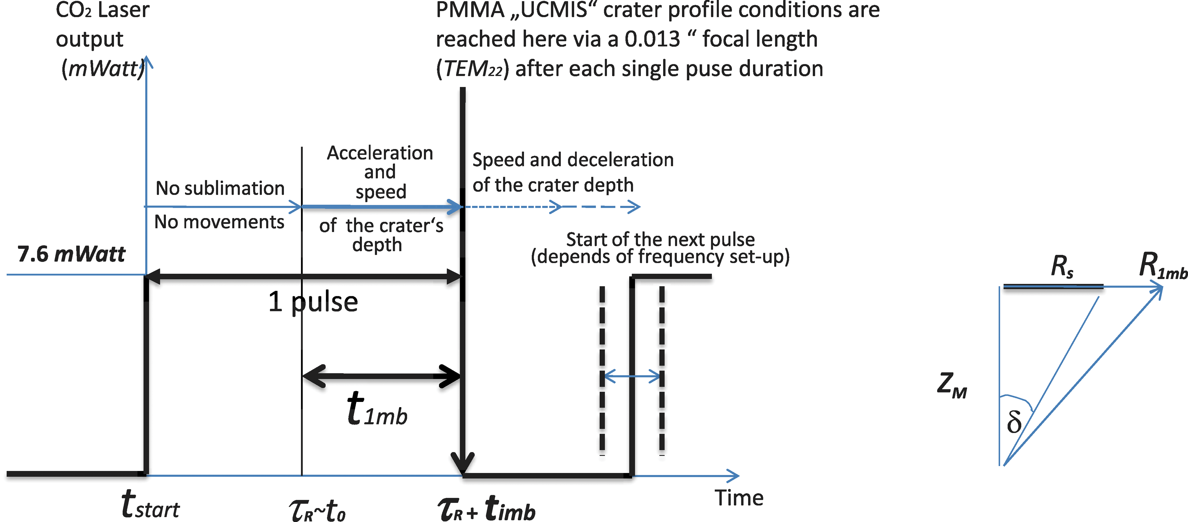
The laser parameters set up for the UCMIS limiting crater profile creation after one pulse.
Then, from room temperature, the absorbed energy reaches the ablative condition threshold on the surface of the irradiated media at
where, again,
In parallel, the LCA Algorithm by Canestri
4
–6
(Appendix) predicts the existence of a “volumetric threshold time”
The key relationship to start with is the one involving R
1b
In other words:
Then, using Equations (1) and (2), and solving Equation (3) by
However still from Equation (3), as:
we can also write:
with t 1mb < t 1b.
From here, the annotations will include the letter “m” and “max” to indicate the biggest possible value of a certain parameter amongst all the different minimum values which can be mathematically calculated for the same parameter: In other words, the maxima (max) of several possible minima (m) of the same parameter.
For brevity, we will therefore define all the annotations as follows :
From Eq. (4) we have:
with
Combining Equation (7) with Equation (6), we have:
or, defining
where, from Reference 1, we have seen that:
From basic optics, 7,8 there is a relationship between the focal spot size 2 Rsmb , the wavelength λ, the diameter of the beam D, and the non-Gaussian TEM22 profile of the focused beam, described by the m2 parameter defined as M 2 =2 n + 1=5 (TEM stands for “transverse electromagnetic mode”).
This TEM represents a large population of commercial beam profiles used in surgery (Fig. 2). For this laser beam, and defining with D=0.345 cm the diameter of the beam before being focused by the focusing lens (data from the laser manual by the manufacturer), we can write this relationship as follows (assuming that the diameters of the beam D and of the focusing lens are >95% equal): The main parameters involved in the lens–beam calibration.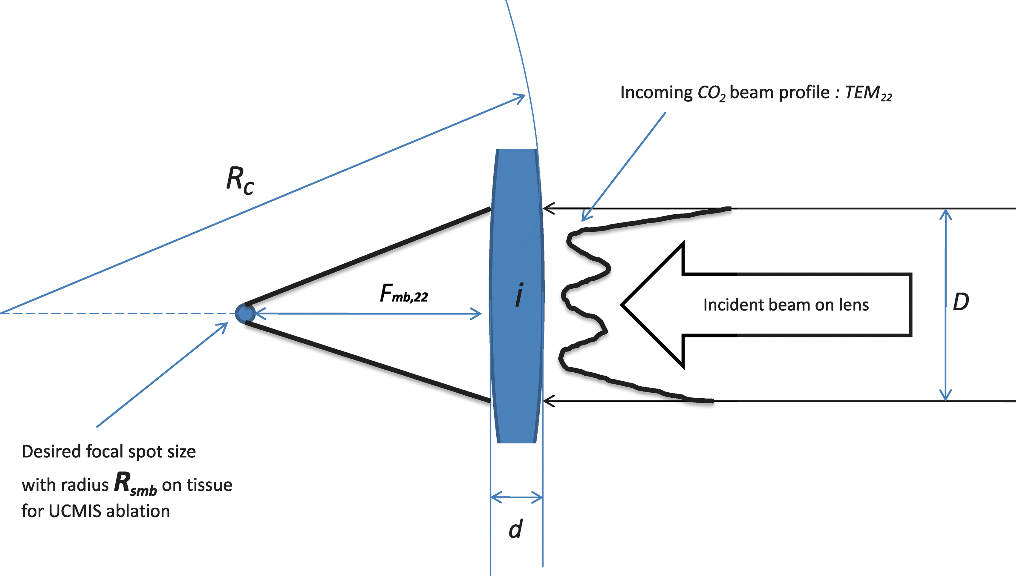
In Reference 1, the author has demonstrated that
The early penetration of the beam across the PMMA is strongly dependant upon both the acceleration at the starting point of the irradiation and the subsequent speed of the sublimation boundary along the z-axis, and in particular within the length of 1/
For this reason, the author proposes to take into account the following four different combinations resulting from
At this point, it is fundamental to remember that, because of the very short time periods considered here and because of the the microchemical structures of the PMMA exposed to the radiation, both “pure acceleration” and “pure speed” contributions cannot be expected, but rather they are mixed at the threshold of each component “time”=τ R and “time”=t 1mb of the same pulse. Deceleration must be expected also (Fig. 1, Section 1).
The crater creation process is very dynamic; therefore, clear transitions from acceleration to speed are seldom, and therefore it can happen that the evolution of a crater follows either
1. Assuming the same acceleration
Using the definition of τ
R
[Eq. (1)], we have:
Separately, combining Equation (4) and Equation (10) with Equations (12) and (14), one can easily calculate (Table 1) the maxima of Rsmb , fmb and Z 1mb (for TEM22) for one single pulse at Wmin=7.6 mW lasting a time period equal to τ R + t 1mb (Fig. 1, Section 1).
These values represent the maximum limit in R, Z, and f to be considered under the present UCMIS regime. Therefore, the true minimal values must be smaller than these ones.
Finally, again from Equations (4), (10), (12), and (14), and observing Fig. 1, one can say that:
and therefore:
This brings us to: ɛ vol < 0.29, which is defined as the lateral beam penetration coefficient along the crater's walls.
2. Assuming the same speed
From Equation (11):
From Equation (9) and from Table 1:
in which we have considered ɛ
z
=1 because, from Equation (6), we also showed that:
From Equation (6) and from Table 1 we have:
to calculate the ideal sublimated UCMIS volume v
1mb
using the next equation:
The author suggests splitting the contributions of α
vol
along the three coordinates z and x=y to be able to calculate the geometrical beam exposure coefficients Be of the media to the incoming irradiating beam as a function of the three geometrical axis and of the lateral beam penetration ɛ. From Equations (19), (21), and (22), we have:
and also:
From Equations (14), (23), and (24), we can calculate:
which perfectly matches with Equation (17) obtained via the speed equality, and it is linked to 0.5” at 10 W CW irradiation. 5 It is possible to have found a PMMA time constant at sublimation (see also link to crater development speed in Equation 35).
3. Assuming the same acceleration
Using all the numerical values calculated so far for a TEM22 beam profile, and from Table 1, we have:
and therefore from Equation (11):
However, in order to take into account the dependability of the focal length from the generic TEMnm profile of the irradiating laser beam,
9
we can rewrite Equation (28) as follows:
Particularly for TEM22, we have n=2 and, therefore, for the same x=Rsmb, Equation (29) becomes Equation (28). Equation (29) is the fundamental law which correlates the desired irradiating laser beam spot under UCMIS conditions with the beam profile TEMnm mode in use (CO2 laser type from manufacturer).
For a pure Gaussian beam profile, we have n=0; therefore, Equation (29) becomes:
For the same R
smb of Equation (27), we have:
In conclusion, the less Gaussian-looking CO2 laser beam profile one uses, the shorter the focal length becomes, providing that the same desired spot radius is kept constant to avoid unwanted later damages. TEM22 is indeed the most representative mode for many the commercially available surgical laser today, therefore the result reported in Equation (28) can be used as a reference for several manufacturers. For a pure Gaussian beam profile, the focal length is always longer for the same spot radius. Reading Equation (29) more carefully, for an infinitive large laser beam profile, the focal length tends to zero (clinically not relevant): the same happens, obviously, for a laser spot of zero radius as well.
From Equation (11) again, the value of D=3.45 mm is typical for most of the commercially available medical CO2 lasers today.
Excellent correlation can be also observed with the following forth and last model.
4. Assuming the same speed
Therefore, also from Table 1:
and again from Equation (11), we find exactly the same result as in Equation (28):
Assuming a uniformly accelerated regime, we have from Equation (25) and from the formulation of
which is in perfect correlation to the horizontal speed evaluation already published. 1 This result points to the speed V start as a possible constant for PMMA on all the x, y, and z axes for very short pulse durations.
This fact is also linked to the other possible time-related universal constant described in Equation (25), although further investigations are needed to validate and confirm this relationship and its meaning.
The good correlation among the four proposed combinations presented previously suggests the equivalent influence produced by the acceleration and speed of the crater depth creation during the very early phase of the sublimation in PMMA samples and during the duration of each pulse.
Crater Profiling Obtained Under UCMIS Regime
From Equations (23) and (24), knowing that α z =536.9 cm−1, we calculate α xy =607.4 cm−1 However, 536.9 cm−1 must remain constant independent from any geometrical axis. 1 The coefficient Be (beam exposure) helps, therefore, to vertically and horizontally balance this physical requirement (Fig. 3, Section A).

The UCMIS limiting CO2 crater profile conditions for 0.013“ and after the first pulse.
Horizontally and only at the surface level, we have (607.4 Be )cm−1=536.9 cm−1, or in other words, ɛ xy =Be =0.88. Vertically is ɛ z =Be =1, as demonstrated in Equations (6) and (19), whereasɛ vol =0.29 is the lateral beam volumetric penetration degree immediately under the surface from Equation (16).
In conclusion, normalizing to 1 (100%) both the penetration and the beam exposure along z, then laterally on the plane x-y, we have Be =88%, whereas laterally along the crater walls (z) we have an exposure of Be =12% associated with volumetric beam penetration of ɛ vol =0.29.
Mathematically, the forming crater has curved conic walls on the side because of 0.29, and it is not as flat as it could be because of linear regression between 1 and 0.88 (the value 0.44 would generate a classical lateral linear conic shape, Fig. 3, Section B). Physically, this corresponds to the fact that the curved shape is caused by: (1) the ratio “same W incident / increasing lateral exposed surface”, so less and less heat is incident laterally to create sublimation; (2) the reflection on the steep walls toward the bottom; and (3) the lateral conduction of heat away from crater through the healthy tissue (Fig. 3, Section C.)
Laterally, the temperature is high but not up to sublimation, leading to thermal shock and subsequent irreversible permanent thermal damage.
This conclusion is very important in the utilization of the crater shape under UCMIS conditions, because it shows limited later side cutting capabilities of the beam during the first pulse at the end of
Lens Calibration Requirements
For the case of a lens with index of refraction i (example : i of silica), with thickness d and surface with radius of curvature R
c, the effective focal length f is given by
7
:
which means, from Equation (11) in case of a generic CO2 - TEMnn laser beam profile (Fig. 2):
As a practical example, it might be useful to show the relationship existing among a known beam diameter before being focused, the thickness of the focusing lens, its curvature, and its focal length. For a silica lens of known i and for a TEM22 beam profile with the spot radius Rsmb
=3.23·10−4 cm on the irradiated media, the lens manufacturer must develop a lens such as (in mm):
This equation takes into consideration the beam diameter before the lens [see explanations for Equation (11)] and the resulting focal length [Equations (28) and (34)] equal to 0.013”. Using Equation (38), we can see that for a lens thickness d=1 mm, then Rc =0.235 mm, whereas for d=0.5 mm we have Rc =0.166 mm for the same focal length of 0.013 “=0.33 mm > Rc, and spot with diameter 2Rsmb =6.46·10−4 cm.
Equations (37) and (38) can be used by the manufacturer to plot the thickness of the lens versus its curvature radius to find the best calibration process of the lens. The obtained optic will provide the required case-by-case UCMIS spot to be used during each particular surgery, providing that the TEM mode and the diameter of the CO2 beam (before being focused) are known.
Conclusions
In this article, the author has presented and discussed the relationships between the main optical, thermodynamic, and time-dependent parameters linked in the creation of the smallest possible crater dimensions in PMMA following TEM-dependent CO2 laser beam profiles in pulsed mode.
The presence and the combination of acceleration-, deceleration- and speed-related components in the early phase of the crater sublimation, and during each single pulse duration, have been demonstrated. Thanks to these results, the manufacturing steps needed to create a lens for laparoscopic applications of UCMIS protocols is proposed and the complete results are reported in Table 2.
Further investigations are needed to completely validate the global procedure before adopting it in real-case surgical operations on living organisms.
Footnotes
Acknowledgments
The author thanks the University of Tel Aviv, Tel Aviv, Israel, for the use of the laboratory of the Sackler Faculty of Medicine to acquire the experimental results needed to write this article.
This article is dedicated to my sons Fabrizio and Riccardo.
Author Disclosure Statement
No competing financial interests exist.
Appendix: The LCA Algorithm
In 1992, the author demonstrated 4,5 the existence of a very simple empirical law that allows one to forecast the volume ablated by a CO2 – TEM22 laser beam (M 2=2n+1=5) in PMMA and compact bone samples.
The main equation combines several values of the focal length of the focusing head in use to the R(t) and Z(t) development curves of the crater diameter and depth versus the exposure time of the sample to the radiating beam. After comparing the geometrical details of several hundreds of craters in PMMA against focal lengths, TEM modes and beam widths of the laser beam, this fundamental equation can be written as follows :
where V(te , fk , FSb ) is the resulting crater volume, f k is the focal length in use, f b is the basic focal length, FSb is the Focal Sequence of both f k and f b, while t e is the exposure time and v b(f b) is the basic volume of FSb.
The following definitions have been introduced:
The FS b and f b are defined as follows (arrows indicate one or two examples out of all possibilities, unit length is the inch):
It has been demonstrated10 that v
b=
If we put V(te
, fk
, FSb
)=v
b(f
b) in Equation (A1), we obtain the basic equation
which is the first step for any investigation about the starting phase of the ablation processes associated with a measurable and known geometrical shape.
Additionally, the following definitions have been used :
Their minimum values generated by the smallest focal length are therefore Z1mb and R1mb
Because, however, there might be more than one of those