
Abstract
Introduction
L
In terms of laser dentistry, we note that human enamel is an uneven material. Therefore, when using ultrashort-pulse laser ablation, there can be problems in controlling ablation accuracy. The output form of the laser energy is a light spot, which means that point ablation occurs. Therefore, the majority of ablation error is reflected in the ablation depth. 4 Consequently, controlling the depth of ablation is of primary importance.
In this light, we examine here the quantitative relationship between the timing of the focal-plane-normal stepping of a three axis, numerically controlled picosecond laser and the single-step size of the depth error for human enamel cavity preparation. Further, we attempt to establish a depth-control method in enamel cavity preparation via focal-plane-normal step-parameter optimization of the laser. Enamel is mainly removed in tooth preparation; therefore, the evaluation of precise depth-control methods for ultrashort-pulse laser enamel ablation can effectively avoid damaging the surrounding hard and soft tissues while achieving highly accurate three-dimensional laser grinding. Such an approach may provide a strong foundation for future developments in oral clinical precise and automatic tooth preparing.
Materials and Methods
Equipment and methods
Equipment and software
Laser system: picosecond laser (wavelength, 1064 nm; pulse width, 15 psec; repetition frequency, 100 kHz; power, 30 W; laser focal-light spot diameter, 38 μm).
We used a three axis laser scanning device with a mini-numerical-control galvanometer that was developed and constructed in-house (lens focal length, 175 mm; light-spot scanning speed for the two-dimensional scanning galvanometer, 1900 mm/sec; light-spot overlapping rate within and between the scanning lines, 50%; minimum step size along the z axis, 0.1 mm; maximum step size, 10 mm). We also programmed the numerical control software used to operate the laser system.
The sample-stage position-control device was a spiral micrometer (Mitutoyo Corporation, Japan; accuracy, 0.01 mm).
The three-dimensional measuring device was a three-dimensional laser scanning microscope (Keyence Corporation, Japan, VK- X200).
Materials
A total of 24 freshly removed mandibular first molars were collected from the Oral and Maxillofacial Surgery Clinic at the Peking University Hospital of Stomatology.
Methods
Sample preparation
Calculus and soft tissues on the dental surfaces were removed using an ultrasonic scaler and the surfaces were rinsed clean with saline. The crowns and the roots were cut transversely along the cementoenamel separation using a diamond wire cutter (Shenyang Kejing Instrument Co., Ltd, STX-202). The diamond wire was moved parallel to the cross-section towards the crown, producing dental hard tissue sample slices of 2 mm thickness. These slices consisted of a round inner portion of dentin surrounded by an external enamel layer of at least 2 mm width (Fig. 1). The surfaces for ablation were polished using 800 and 1000 grit waterproof sandpaper to form essentially flat surfaces; they were then submerged in formalin solution until use. The samples were divided into two groups: 42 sample slices from the first group were used in ablation with a fixed focal plane position and 6 sample slices from the second group were used in stepwise ablation along the focal plane normal.

Dental hard tissue sample slice.
Ablation with fixed focal plane position
The sample was mounted on an electrical spiral micrometer sample stage; the ablation surface was oriented perpendicular to the picosecond laser beam and positioned at the focal point in front of the center of the lens using two vertically placed spiral micrometers (Fig. 2). The picosecond-laser path was modeled computationally using software (Fig. 3). The frame for the laser was a square with an outer-side length of 5 mm and inner-side length of 3 mm, and the ablation section covered both the dentin and enamel regions. The space between the frames was set to 19 μm. The light-spot diameter was 38 μm, the surface scanning speed was 1900 mm/sec within controllable scanning lines, and the light-spot overlapping rate was 50%. The control software automatically calculated the number of frames to be scanned, and it also performed two-dimensional scanning and ablation of the laser spot from the outside to the inside, starting from the focal plane. The number of additive pulses was n (one additive-pulse layer denotes the completion of one ablation motion from the outer to the inner frame by the laser, and, therefore, n represents the layer number). The 14 enamel–dentin slice surfaces were scanned for n=10, 15, 20, 25, 30, 35, 40, 45, 50, 55, 60, 65, and 70 layers in the given order. The ablation of each additive pulse layer value was repeated three times, yielding a total of 42 samples.

Experiment platform and spot diameter measurement.
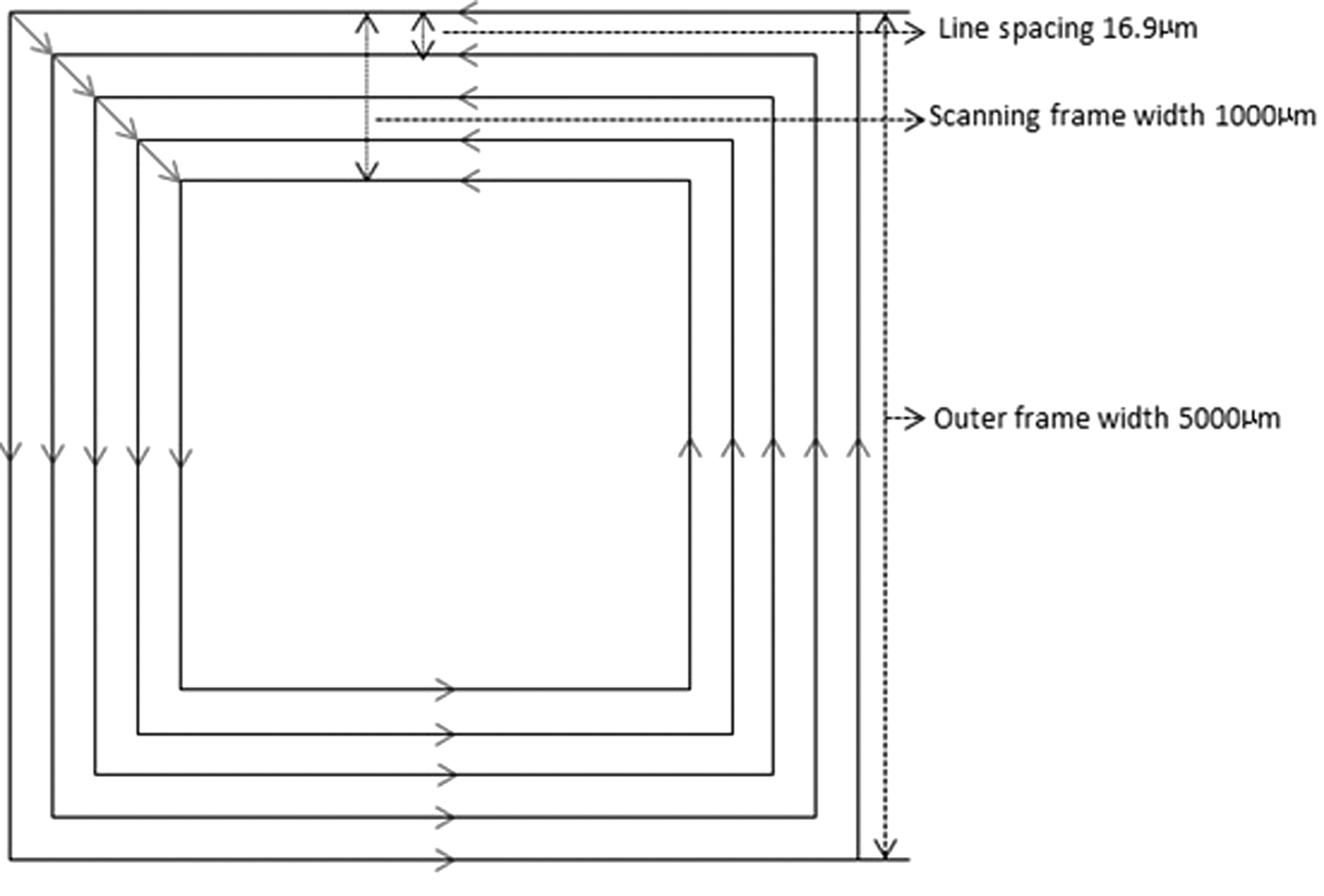
Two-dimensional motion paths of picosecond laser spot.
Measurement of two-dimensional scanning-ablation depth
A three-dimensional shape-measurement laser microscope was used to measure the actual ablation depth, d, for each slice (actual two-dimensional scan-ablation depth with fixed focal plane position). In total, 40 points were selected at the base of the ablation of each enamel section (the points were distributed as evenly as possible on the cleaved surface). With the upper surface as a reference, the depths of the 40 points were measured to calculate their average. Three repeated ablations were made for each n (additive-pulse layer) value to calculate an average. Hence, actual ablation depths, corresponding to each n value, were recorded. A maximum ablation depth value for the two-dimensional ablation was thus obtained, along with a plot of the quantitative relationship between ablation depth and additive-pulse layer.
Three-dimensional scanning and ablation in stepwise increments along focal plane normal
The parameters for this process, such as the focal-plane two-dimensional scanning path, were set as described previously. The timing for the stepwise increment along the normal was set to 5, 10, 15, 20, 25, 30, 35, 40, 45, and 50 layers. The single-step size was obtained from the linear regression function of the quantitative relationship between ablation depth and additive pulse layer. The number of steps was set to 9, 4, 3, 2, 2, 1, 1, 1, 1, and 1. Ten square cavities (2×2 mm) were cut into the enamel regions in each of the enamel–dentin mixed slices. This was repeated for six sample slices.
Measurement of three-dimensional ablation depth
A three-dimensional shape-measurement laser microscope was used to measure the actual total ablation depth, d2 , of each square cavity using the method described previously. The theoretical total ablation depth d1 =d0 ×(t+1), where d0 denotes the theoretical single-step ablation depth and t denotes the number of steps. The error in the total depth, e, was also calculated. The error in the focal-plane single-step ablation depth was then calculated as e1 =(d2 / t+1) - d0 . The relationship among e, e1 , n, and d was subsequently analyzed.
Results
Two-dimensional ablation
Table 1 lists the n and d values corresponding to each laser ablation in the enamel region. The maximum d value was 674.24 μm, with n=60.
The quantitative relationship between n and d showed an increasing trend within the range of the maximum ablation depth. Through linear fitting, the function equation and fitting coefficient were computed as d=10.16n - 6.04 and R 2 =0.9778. Figure 4 shows the qualitative relationship between n and d, as well as a linear-fitting plot.
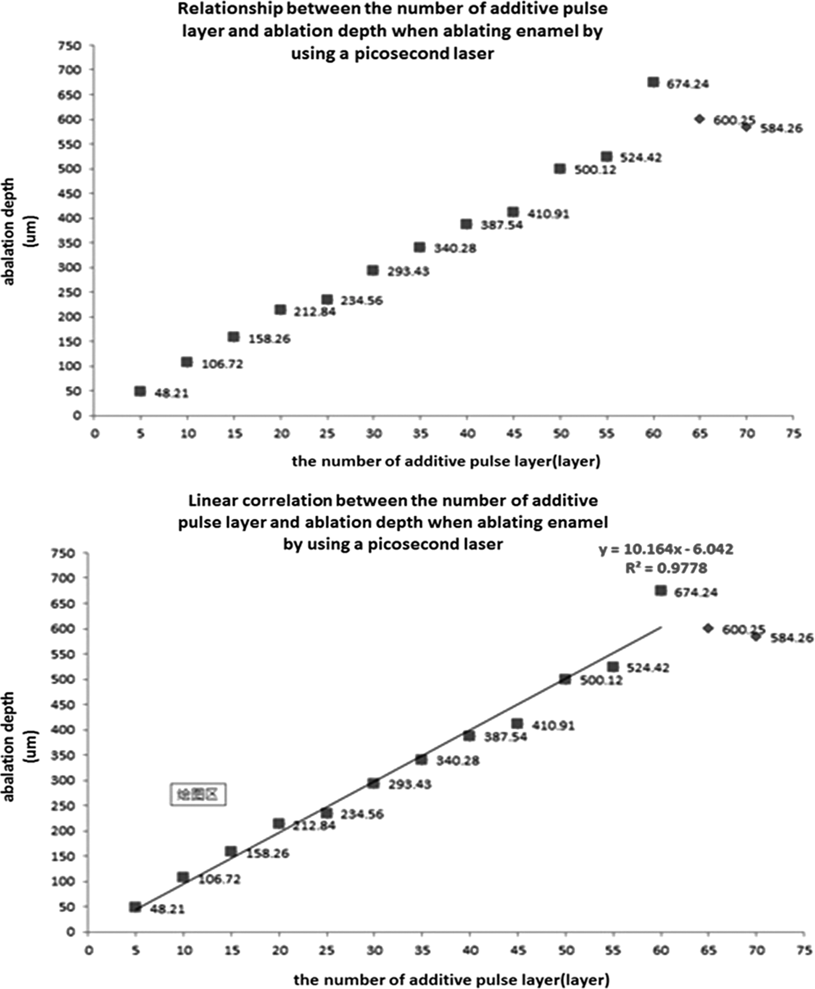
Linear fitting plot and quantitive relationship between the number of focal plane additive-pulse layers, n, and ablation depth, d.
Three-dimensional ablation
A three-dimensional shape measurement laser microscope was used to measure d2 . The values of d1 , e, d0 , and e1 were calculated, and these values are listed in Table 2.
From the table, we note that for n=5, the error in the total depth reached a minimum value of 2.25 μm. Therefore, the depth error was controllable on the micrometer scale.
Discussion
In this section, we attempt to relate our findings to other studies in this area. Sun et al. 4 –8 used a Ti:sapphire femtosecond laser system (CPA-2001, Clark-MXR, USA) to conduct a preliminary study on the surface appearance and changes in dental tissue morphology as well as the control of the medullary cavity temperature and ablation efficiency with dental hard tissue. Their results showed that numerically controlled femtosecond laser ablation yielded a smooth surface and boundaries with clear lines and corners in hard dental tissue, and that the increase in medullary cavity temperature could be controlled to within 5.5°C, using compressed-air cooling at room temperature. In addition, it was found that the ablation efficiency for dentin was significantly higher than that for enamel. However, the purchase and operation of femtosecond laser equipment is prohibitive. In this light, the application of another type of ultrashort pulse laser, the picosecond laser, has improved the prospects for the practical application of dental ablation. Current research in China and elsewhere mainly focuses on the micromorphology, thermal effects, and ablation efficiency of picosecond-laser hard-dental-tissue ablation. 9 –12 On the other hand, there have been fewer studies on ablation-depth control methods with picosecond systems.
Studies by Lizarelli et al. 13,14 showed that, at equal energy densities, picosecond laser ablation efficiency on dentin was approximately eight times that on enamel. This is primarily because dentin contains a large amount of collagen compared with enamel, making it easier to ablate. Sun et al. 8 conducted a preliminary study on the depth-error control method of a numerically controlled picosecond laser in human dentin ablation. They found that when scan-ablating dentin using a 30 W three-axis picosecond laser at a wavelength of 1064 nm and a repetition frequency of 100 kHz, the focal plane additive-pulse layer, the errors of the step increment along the normal and single-layer ablation depth, and the total ablation depth error showed positive correlation. By adjusting the single-step size and the step timing along the focal plane normal when ablating dentin using a numerically controlled picosecond laser, the single-step ablation depth error was controllable at the micrometer level. Based on this study, our research group further investigated the dentin-cavity-ablation depth-control method and evaluated its effect based on three-axis, numerically controlled picosecond laser focal-plane-normal step-parameter optimization. The experimental results showed that when the timing of the stepwise increment and single-step size along the focal plane normal were set at five additive pulse layers and 45 μm, respectively, the single-step ablation depth error was minimized (0.05 μm); then, when a square cavity was ablated with a depth of 420 μm, the depth error was 2.75 μm.
Next, we discuss the need for superimposing the focal and ablation planes. Laser energy exhibits a non-uniform Gaussian distribution. When a dentin surface moves out of the focal plane, the energy density at the periphery of the light spot decreases; whereas at the center, this energy may still be above the dentin-ablation threshold. With existing methods, the single-spot ablation surface may take on the appearance of volcanic craters, 15 and the successive superposition of many light spots will lead to an increased depth error in the ablation surface, which is unfavorable in regard to ablation accuracy control. Therefore, in theory, the ablation surface of interest should be kept superimposed onto the focal plane (along its normal) during ablation in order to ensure that each dentin surface element targeted by light spots can reach the same ablation depth (or the same depth with minimal difference), thus reducing the single-step ablation-depth error. The results of this study showed that by reducing the additive-pulse layers of the two-dimensional scan with a fixed focal plane and focal-plane-normal single-step size, the single-step dentin-ablation depth error was controllable on a micrometer scale.
Finally, we discuss the rationale underlying our choice of light-spot diameter and overlapping rate. The picosecond laser is a pulse laser of which each pulse can be considered a light spot. Previous experiments have demonstrated that a 50% light spot overlapping rate can produce an ablation surface in dental hard tissue that is smoother and flatter than those yielded by other laser treatments. 6 During linear scanning, the light-spot diameter, scanning diameter, and scanning speed all influence the light-spot overlapping rate; whereas during surface scanning, the distance between the scanning lines determines the inter-line light-spot overlapping rate. In this study, we set the light-spot diameter to 38 μm, the linear scanning speed to 1900 mm/sec, the repetition frequency to 100 kHz, and the light-spot overlapping rate with lines at (1900×1000 μm /100,000 pulses)/38 μm=50%. The distance between the scanning lines was set to 19 μm, and the light-spot overlapping inter-line rate was set to 19 μm /38 μm=50%. Using the aforementioned settings, we obtained smooth and flat ablation surfaces.
Although we obtained such smooth, flat ablation surfaces for dentin in our study, we note that during actual clinical dental preparation, the hard dental tissues to be removed contained both enamel and dentin. Meanwhile, the composition of enamel and dentin, which includes the density of dentinal tubules, as well as the amount of water and organic material, are different from one tooth to another, and also from the different parts of the same tooth. It may have great influence on the precise ablation. The choice of whether to adjust the laser output parameters according to the ablation object under study or to use a single set of strongly compatible parameters may determine the means for highly accurate ablation on the two types of dental hard tissues and may produce a preparatory shape that satisfies clinical requirements; this constitutes a topic for further research.
Conclusions
Our experimental results demonstrate that when ablating enamel two dimensionally, using a numerically controlled picosecond laser, the number of focal-plane additive pulse layers and the ablation depth exhibit an overall positive linear correlation. In three-dimensional ablation, when the single-step size along the focal plane normal is set to be equal with the two-dimensional scanning-ablation depth, the number of focal plane additive pulse layers and the single-step size along the normal are positively correlated with the single-step ablation-depth error and the total ablation-depth error.
By adjusting the timing of stepwise increments along the focal plane normal and the single-step size, the depth error of ablating human enamel via a numerically controlled picosecond laser can be limited to within 0.04 μm per step. When the timing of the stepwise increment and single-step size along the focal plane normal were set to five additive pulse layers and 45 μm, respectively, the ablation of a square cavity with a depth of 450 μm had an enamel-ablation depth error limited to within 2.25 μm. In light of these results, we believe that this work may significantly contribute to the development of laser dentistry.
Footnotes
Acknowledgment
This study was supported by the National Science & Technology Pillar Program during the 12th Five-Year Plan (Grant no. 2012BAI07B04), the National High Technology Research and Development Program (“863” Program) of China (Grant no. 2013AA040802), and the National Natural Science Foundation of China (Grant no. 81271181).
Author Disclosure Statement
No competing financial interests exist.