
Abstract
Abstract
A soft morphing ray propulsor capable of generating an undulating motion in its pectoral fins was designed and fabricated. The propulsor used shape memory alloy for actuation, and the body was made with soft polymers. To determine the effects of undulation in the fins, two models that differed in terms of the presence of undulation were fabricated using different polymer materials. The experimental models were tested with a dynamometer to measure and compare thrust tendencies. Thrust measurements were conducted with various fin beat frequencies. Using the experimental data, the concept of an optimized standalone version of the ray robot was suggested and its prototype was fabricated. The fabricated robot was able to swim as fast as 0.26 body length per second and 38% more efficient than other smart material-based ray-like underwater robots.
Introduction
I
Among the numerous underwater animals, rays (batoid fishes) have a peculiar body shape and swimming method. 7 While most underwater animals use their caudal fin, located at the end of the tail, to generate thrust, rays usually flap their pectoral fins, located on each side of the body, for locomotion. The pectoral fins consist of numerous cartilage structures with muscles attached in a radial direction, which makes elastic shape changes possible. Figure 1 shows the actual skeleton of a stingray and the cartilage structure of the pectoral fins. The red marks show the shape and direction of the cartilage, which grow radially from the body.

Bone structure and cartilage fin of a ray. Color images available online at www.liebertpub.com/soro
With this, sufficient thrust can be generated with a lower fin beat frequency than other caudal fin-based animals and also has the advantage of great maneuverability.8,9 Mimicking these features, various studies on fabricating underwater robots have been conducted. Ma et al. developed a biomimetic cownose ray robot, driven by a DC motor, which can swim with both twisting and oscillating fins. 10 However, there are some limitations in realizing continuous fin motion with link structures and motor devices. Thus, research using smart material and soft polymers for robots has also been conducted. Wang et al. fabricated a biomimetic manta ray robot with shape memory alloy (SMA) wires within a latex membrane fin. 11 Takagi et al. used an ionic polymer metal composite (IPMC) instead of SMA. They also fabricated an undulating flexible fin with a series of IPMC actuators and soft polymers. 12 Chen et al. developed a manta ray robot also using IPMC and soft polymers. They controlled the twisting angle of the pectoral fins and measured the power consumption of the robot. In addition, the stand-alone robot was fabricated, and free swimming was successfully done. 13 Recently, research groups at the Massachusetts Institute of Technology and Princeton University have been developing biomimetic ray robots. Cloitre et al. developed a stingray robot that used a pair of motors for actuation and soft silicone for wave propagation. Power consumption of the actuators was simulated and measured for comparison. The free swimming velocity and its thrust were also evaluated. 14 Smits and colleagues designed a free-swimming manta ray robot with soft, flapping pectoral fins. In preliminary research, they conducted an experiment with a flexible panel actuated with heave oscillation at its leading edge. They concluded that there was an advantage in propulsive efficiency with high flexibility and low speed. 15
Among the numerous smart actuators, the SMA has advantages in generating a relatively high shortening force and is easy to treat among the various smart actuators. It has thermomechanical characteristics, related to the temperature and internal stress of the material, which make it possible to actuate at high frequencies, if provided with sufficient cooling. In addition, large volumes are not required relative to the motor and linkage module, making it possible to fabricate small-scale robots. For this reason, many studies using SMA wires to provide actuating forces have been conducted in various areas. Song et al. fabricated an SMA-based actuator that could flap at over 10 Hz. Multiple thin SMAs were embedded in soft polymer so that the cooling time could be reduced. 16 In addition, Lee et al. fabricated a neck immobilizer using SMA for the driving force 17 and Rodrigue et al. conducted a parameter study on a twisting actuator, which also used SMA as a force generator. 18 In this research, an SMA was also used as a force generator for actuation of the robots.
Previous studies have successfully fabricated ray robots that mimic the movements of the pectoral fins using various methods. However, only the swimming motions or body shapes were mimicked, with no detailed analysis of the swimming mechanisms of rays. In this research, the ray's movements were mimicked using smart materials and a simple mechanism. In addition, experiments to confirm the effect of the undulating motions of the ray's fins during swimming were conducted. The main actuator of the fabricated propulsors was a smart soft composite (SSC) actuator, which includes SMA as a driving force generator. SSC is composed of SMA and a directional scaffold embedded in a soft polymer, which makes a bending motion possible by shortening the SMA. 19 Using this SSC structure, Wang et al. fabricated a crawling smart phone robot that mimicked an inchworm robot's movements. 20 To fabricate a ray propulsor, SSC actuators were attached to the front side of the polymer fins for vertical oscillation. To verify the effect of the undulations, another propulsor, with undulation controlled using a different polymer material with a different elastic modulus, was also fabricated. For these two propulsors, swimming experiments were conducted with various fin beat frequencies. Thrust was measured in each condition for comparison.
Background
Rays and skates have various swimming methods, according to the species. Some species, such as the guitarfish (Rhinobatidae), have wide pectoral fins, but primarily use their caudal fins for thrust generation. Other species usually use their pectoral fins, which undulate with various shapes and frequencies.
In this research, we focused on pectoral fin-based locomotion. According to research by Rosenberger, such rays can be categorized into three types according to the number of waves generated by the pectoral fins during a fin stroke. Figure 2 (upper) shows a schematic of the different swimming motions. Oscillators that show minimum undulation and generate thrust mainly by an oscillating motion (<0.5 waves per fin) tend to have a large body and travel long distances with a minimum of movement. The intermediate type generates thrust by both undulating and oscillating motions (wave number: 0.5–1.0). 9 This type of ray tends to show slower fin movements than rays with undulating motions, but has an advantage in terms of long-distance swimming. Undulators generate thrust mostly by undulating motions of the fins (>1.0 waves per fin). This type of ray tends to show rapid fin movements over shorter distances. In recent work, Blevins and Lauder claimed that undulators have a disadvantage in swimming efficiency due to a ground effect, but a rapid undulating fin movement is a method of overcoming this. 21

Different swimming motions of rays: oscillator, intermediate, and undulator 9 and schematic of vortex and force generation through undulating motion. 22 Color images available online at www.liebertpub.com/soro
In this research, we sought to confirm the existence of undulating motions in the same oscillating fins. For this reason, an intermediate-type butterfly ray (Gymnura micrura) was mimicked as our experimental propulsor. According to Clark's research, the undulating motion of the ray's fins generates multiple vortices on the upper and lower sides of the fin (Fig. 2). 22 In most caudal fin-based fish, impulsive thrust generation occurs in a single stroke because the number of waves in the tail is small. However, the generation of multiple vortices occurs in a ray's single stroke, so that it is possible to provide relatively continuous thrust. In this research, a thrust-measuring experiment was conducted to confirm the effects of undulation in the same stroke. In addition, by performing measurements at different fin beat frequencies, it was possible to verify the relationship between frequency and undulation.
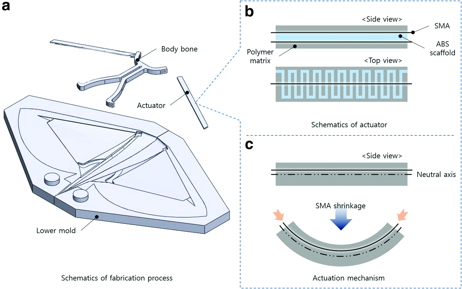
Basic movements of the propulsors are based on the capabilities of the SSC actuator. Figure 3 shows the composition of the SSC actuator and the fundamentals of its actuation. The SSC actuator consists of the SMA, scaffold layer, and matrix material. The basic shape is the beam shape, with active layers, including SMA wires and anisotropic scaffold layers. Anisotropic scaffold layers are located on the neutral surface of the beam. It acts as a firm neutral surface and also as bending angle controller. According to the scaffold's anisotropy angle, the whole actuator's bending and twisting tendency varies. In this research, the actuator was designed only for pure bending. For this, the scaffold layer was at 0° only. The active layers included SMA wires that shorten when current is applied. The SMA shortens with heat generation because it acts in resistance to the current applied to the wire. SMA wires are located eccentrically from the neutral surface, which bends the whole structure when actuated.

Schematics of the smart soft composite (SSC) actuator:
Because the SSC actuator uses SMA for force generation, the surrounding temperature can be key to the actuation time. Figure 4 concerns the experiment in which actuation tests were performed in air and water. Figure 4 (upper) shows the bending motion of the actuator specimen. For comparison, the curvature of each moment was measured. The air temperature was 23°C (i.e., room temperature), and the water temperature was 18°C. Figure 4 (lower) shows the results of the experiment. It can be seen that if the temperature is low, as in water, the acting speed is slow, but the retracting speed is much faster than in air. In addition, the overall acting retracting speed is faster than in air. Because the water temperature is usually much lower than the air temperature, it can be concluded that the SSC actuator is appropriate for use in underwater robots.

SSC Actuation comparison at different surrounding conditions. Color images available online at www.liebertpub.com/soro
Material, Design, and Fabrication
Flexible polymer was used in the propulsor body for soft-continuous body deformation. Two different polymers that have similar mechanical properties, but differ in elastic modulus, were used as body materials. Table 1 shows the characteristics of the two materials. Both materials have an advantage in the molding process, which is the main process for both the actuator and the propulsor body. Sylgard 184 (Dow Corning, Inc., Midland, MI) has a higher elastic modulus than EcoFlex 0030 (Smooth-on, Inc., Macungie, PA), which is appropriate for fabricating the actuator for an undulation-controlled propulsor (oscillator model). However, EcoFlex 0030 has a low elastic modulus, which is appropriate for fabricating the undulator model. For rigid bone structure, three-dimensional (3D) printed acrylic butadiene styrene (ABS) was used.
The overall shape of the propulsor mimics the butterfly ray, as mentioned previously. Figure 5 shows a schematic design and the dimensions of the propulsor. To mimic the ray's variable fin stiffness, the cartilage area was designed to be thicker than the passive undulating area. This made it possible to deliver force efficiently to the tip of the fin; also, undulation could occur only in the soft cartilage area. The rigid bone and SSC actuator were embedded inside the body. Rigid bone was made with a 3D printer with ABS, holding the actuators. To reduce drag while swimming, the side view shape was designed as an airfoil.

The overall manufacturing processes were based on molding, as in Figure 6. First, the propulsor, according to the issues mentioned above, was designed with computer-aided design. Following this modeling, a body mold was designed by negative modeling. The rigid parts, such as the scaffold in the SSC actuator, molds, and rigid bones, were also designed. Rigid parts were fabricated by layered manufacturing processes using a Dimension SST 768 (Stratasys, Inc., Eden Prairie, MN). Soft parts, such as the actuator, body, and soft cartilage structure, were fabricated by casting processes. Parts using Sylgard 184 were cured at 60°C for 5 h. EcoFlex 0030 parts were cured under the same conditions.
Schematics of
Thrust measurement
Using the models, thrust measurements at various fin beat frequencies were conducted. Fin beat frequency was controlled by the current input. Thrust was measured using a dynamometer (Kistler 9119, Switzerland) at a 500-Hz sampling rate. The ray propulsor was attached to the dynamometer with a rigid aluminum rod (Fig. 7). The experiment was performed at three frequencies: 0.25, 0.4, and 0.8 Hz. Owing to the frequency and force limit of the SSC actuator used, the fin beat frequency was reduced with reference to other species. According to Rosenberger et al., G. micrura's fin beat frequency ranges from 1.06 to 1.50 Hz. The maximum frequency was designed to be the maximum frequency with valid thrust generation. The minimum frequency was set according to the time when the actuator's maximum deformation was reached.
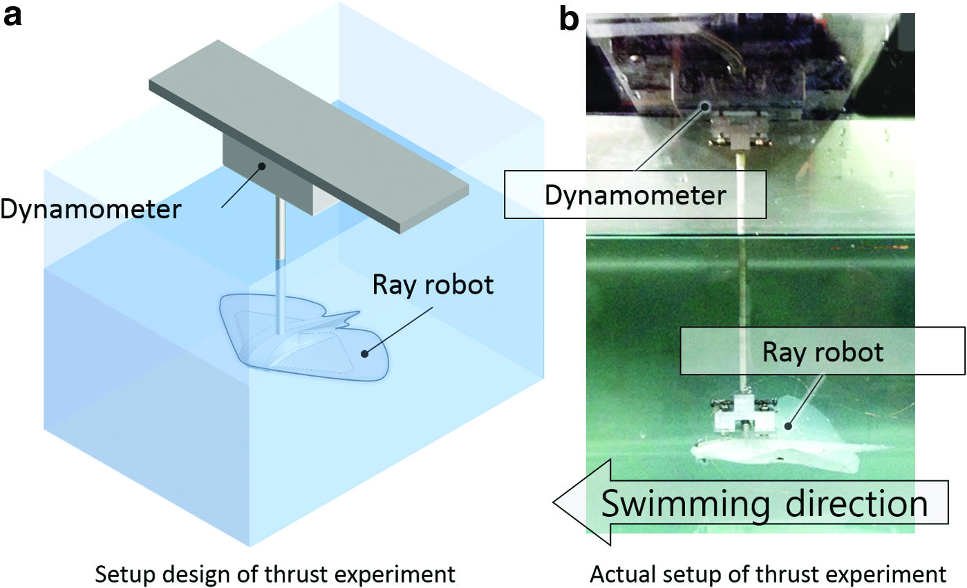
Experimental setups for thrust measurement:
The setup for controlling fin strokes is shown in Figure 8. The input current was patterned using Labview 2012, and the currents were regulated using CompactRIO 9024 and NI 9264 modules. The input current included the magnitude of the current and the delay between SMAs. Because the propulsor requires two channels for up and down strokes, the current patterns are designed as in Figure 9, considering cooling time.

Schematic diagram of the control process.

Current patterns and fin position.
Results
Swimming modes
To confirm that each model showed the intended swimming mode, the propulsors were immersed in still water for actuation. A high-speed camera (SLT A-77; Sony, Tokyo, Japan) was used for taking videos of each model. The results of the swimming behavior are shown in Figure 10, which are snapshots of one stroke in the same period of time. The fin beat frequency was 0.25 Hz, for which the electric current was applied as a step function. As in the figure, the undulator showed more than one wave in a stroke, while the oscillator showed no wave in its stroke. Displacement and velocity were measured using the high-speed camera. Displacements of actuator tip and fin tip were measured using the side view video, and the results are also in Figure 10. According to the displacement result, actuator's displacement in one cycle is similar in both models, but certain phase difference exists only in undulator's motion.

Snapshots of one stroke at the same time point. Actual motion is available in Supplementary Video S1 (Supplementary Data are available online at www.liebertpub.com/soro). Color images available online at www.liebertpub.com/soro
Thrust measurements
Thrust was measured for each fin beat frequency. At each frequency, five measurements were made and average values were used. Figure 11 shows the thrust tendency in one cycle according to the variable fin beat frequency. These graphs are based on raw data from the experiment, which was cut only to display the tendency of thrust. One cycle was defined as neutral status → downstroke → upstroke → neutral status.

Thrust tendency in one cycle for fin beat frequencies of 0.25, 0.4, and 0.8 Hz. Color images available online at www.liebertpub.com/soro
Propulsive efficiency
Using the thrust data and velocity data, some major coefficients were calculated as below. Computations were done referring to the research done by Read et al., Schultz and Webb, and Park et al.23–25 The axes used in the computation are indicated in Figure 12.

Schematics of axis used for the computation. Color images available online at www.liebertpub.com/soro
First, to calculate thrust coefficient (Ct), average thrust force
Using the average thrust force, Ct was calculated as below. Chord length c and wing span s were based on fins' dimension. In case of the speed U, it was considered as an impulsive-start experiment, in which maximum heave velocity was used instead of towing velocity.
As the result shown in the Figure 13b, undulator was over four times efficient in generating thrust with low fin beat frequency. However, as frequency goes higher, the Ct shows steep decline until it reaches similar value with oscillator.

Result of
Mechanical power,
As the function states, Cp increases when fin beat amplitude and frequency increase. As Cp increases, there is a resulting increase in Ct, in both the undulator and the oscillator. However, the increase in Ct in the oscillator is small. This tendency can be represented with propulsive efficiency, η, as below. With propulsive efficiency, the proportion of energy used in locomotion versus that used in actuation can be estimated.
The result is shown in Figure 13. In the case of the undulator, ∼70% of the actuation energy is transferred to swimming forward at a low fin beat frequency. Considering the oscillator's 15% efficiency at the same fin beat frequency, it can be concluded that the undulating motion makes the flapping more efficient. However, the undulator's efficiency decreases as the fin beat frequency increases. When the frequency increases to 0.7 Hz, the oscillator's efficiency reaches 30%, but the undulator's efficiency decreases to 15%.
Discussions
According to the tendency in thrust data in Figure 13, the undulator and oscillator showed definite differences in thrust generation. At 0.4 Hz, the undulator generated thrust during both the upstroke and the downstroke, while the oscillator generated thrust in the opposite direction during the upstroke. The negative value of thrust means that the propulsor would swim in the opposite direction from the desired direction. As the propulsive efficiency illustrates, energy for flapping the fin is transferred efficiently with the undulating fin. From this, we can conclude that passive undulation in the oscillating fin is more effective than simple oscillation to generate thrust in a certain direction. However, with a 0.8-Hz fin beat, both models showed similar tendencies, with repeated positive and negative thrust values. In addition, as in the propulsive efficiency results, the undulator's value was even lower than the oscillator. In recent work by Di Santo and Kenaley, undulator rays living near the ocean bottom lacked swimming efficiency. 26 Unlike oscillator types and intermediate types that show low fin beat frequencies and big heave amplitudes, high frequency and small amplitude could incur higher costs of transfer, as they claimed. To demonstrate this, a more robust and higher frequency is required. In addition, in actual undulator rays, not only the front but every part of the pectoral fin also moves actively. In future work, improving the model using multiple serial actuators with higher frequencies and increasing cooling is required.
As an example application, the concept of a stand-alone ray robot was suggested and a prototype was fabricated (Fig. 14). Battery and control units were embedded within the body. Fins were fabricated with EcoFlex 0030 for smooth undulation. The thrust-generating mechanisms were the same as for the undulator model above. The robot had a 125 mm body length and 220 mm fin width. As a proof of concept, simple swimming experiments were conducted in a 300-mm-deep pool, with a measuring mat on the bottom. The robot floated on the surface of the water without any contact from the outside. The fin beat frequency was 0.25 Hz, consistent with previous experiments. Figure 14 (lower) shows snapshots of the robot during swimming. The mean swimming speed of the robot was 45 mm/s, which is 0.36 body-lengths/s (BL/s). According to Chu et al., 27 smart material-based underwater robots show speeds in the range shown in Figure 15. Thus, the fabricated ray robot showed the fastest movement among the smart material-based pectoral fin robots mimicking rays. The fastest ray robot in the review showed a maximum of 0.26 BL/s, which was 38% slower than the robot made in this research. Nevertheless, the swimming speed was not stable and the buoyancy was not controlled, so that it was not able to swim in the water. Fabricating a stand-alone robot that can swim in the water remains as future work.

Fabricated robot and snapshots of free swimming. Actual motion is available in Supplementary Video S1. Color images available online at www.liebertpub.com/soro

Comparison among biomimetic ray robots. 27 Color images available online at www.liebertpub.com/soro
Conclusions and Future Work
In this research, soft morphing ray propulsors were designed and fabricated. By comparing two different models that differed in the presence of undulation in the fins, experiments on the effects of undulation were conducted. Experiments were conducted with variable fin beat frequencies. It was found that oscillation with an undulating motion in the fin was more efficient than simple oscillation in transferring the oscillation work to generate thrust. However, as the frequency increased, the undulator and oscillator showed no major difference in thrust generation. Finally, for an application, a concept of a stand-alone version of the ray robot was suggested and a prototype was fabricated with an embedded battery and control units. The fin beat frequency was 0.25 Hz, according to the thrust experiment, and undulating motion was achieved using EcoFlex 0030 as the fin material. The fabricated robot was 38% faster than the fastest SMA-based ray robot reported previously. However, the robot was not able to swim in the water due to the lack of a buoyancy control module.
Future work will include fabricating another model that can actuate with higher frequencies, as in actual rays, by designing the actuator considering thermal aspects. This could be used in determining whether a high frequency and small amplitude fin beat is actually efficient. Moreover, a stand-alone version should include a buoyancy control module so that it can swim in water. This may make it possible to measure the robot's speed, which can be used in computing the coefficients in actual swimming.
Footnotes
Acknowledgments
This work was supported by the Industrial Strategic Technology Development program (10049258), funded by the Ministry of the Knowledge Economy (MKE, Korea), and by a grant from the Bio-Mimetic Robot Research Center, funded by the Defense Acquisition Program Administration, and by the Agency for Defense Development (UD130070ID). The English in this document has been checked by at least two professional editors, both native speakers of English. For a certificate, please see: www.textcheck.com/certificate/U8qRBn and ![]()
Author Contributions
S.H.A. conceived the idea and supervised the research. H.S.K. and W.S.C. designed the study. J.Y.L developed the control system. H.S.K. performed the experiments, analyzed the data, and wrote the article, and all authors commented on the article.
Author Disclosure Statement
No competing financial interests exist.
References
Supplementary Material
Please find the following supplemental material available below.
For Open Access articles published under a Creative Commons License, all supplemental material carries the same license as the article it is associated with.
For non-Open Access articles published, all supplemental material carries a non-exclusive license, and permission requests for re-use of supplemental material or any part of supplemental material shall be sent directly to the copyright owner as specified in the copyright notice associated with the article.