
Abstract
Abstract
In this article, we have proposed a novel robotic finger design principle aimed to address two challenges in soft pneumatic grippers—the controllability of the stiffness and the controllability of the bending position. The proposed finger design is composed of a 3D printed multimaterial substrate and a soft pneumatic actuator. The substrate has four polylactic acid (PLA) segments interlocked with three shape memory polymer (SMP) joints, inspired by bones and joints in human fingers. By controlling the thermal energy of an SMP joint, the stiffness of the joints is modulated due to the dramatic change in SMP elastic modulus around its glass transition temperature (Tg). When SMP joints are heated above Tg, they exhibit very small stiffness, allowing the finger to easily bend around the SMP joints if the attached soft actuator is actuated. When there is no force from the soft actuator, shape recovery stress in SMP contributes to the finger's shape restoration. Since each joint's rotation can be individually controlled, the position control of the finger is made possible. Experimental analysis has been conducted to show the finger's variable stiffness and the result is compared with the analytical values. It is found that the stiffness ratio can be 24.9 times for a joint at room temperature (20°C) and at an elevated temperature of 60°C when air pressure p of the soft actuator is turned off. Finally, a gripper composed of two fingers is fabricated for demonstration.
Introduction
P
To realize variable stiffness in soft robots, a number of methods have been reported. Such methods can be divided into two main categories: active and semiactive. 5 Active variable stiffness methods refer to stiffness tuning via the use of active actuators arranged in an antagonistic manner, such as tendons acting with fluidic actuator. 6 Different from active methods, semiactive methods utilize intrinsically adaptive materials to realize variable stiffness. These methods include jamming,7,8 electrorheological (ER) or magnetorheological (MR) fluids,9,10 shape memory alloy (SMA), 11 shape memory polymer (SMP),12,13 low melting point alloys (LMPAs), 14 conductive elastomer, 15 and so on.
Jamming is utilized to obtain variable stiffness because of its fast response and simple operation, but the need of auxiliary equipment such as pumps and valves to produce the jamming effect makes the design of a jamming system complicated. ER fluids and MR fluids also have fast response on an applied electric or magnetic field, but such a field may easily be affected by environments and their high density restricts the operating volume. The phase change of SMA material between martensite and austenite enables it to have the variable stiffness property. However, the stiffness range is small and the SMAs high absolute stiffness would affect soft robots' compliance. LMPAs have a large stiffness range and can be stimulated by direct Joule heating. The main concern of LMPAs is in the liquid state where leakage is difficult to prevent. The unrepeatable shape change of LMPA material in state transition makes the stiffness control impossible. Conductive elastomers have also been used to realize variable stiffness by mixing conductive fillers into elastomers, but the fabrication is time-consuming. SMP is of low cost and easy fabrication while exhibiting a large stiffness range (two orders of magnitude) between rigid and soft states. 16 Unlike other thermoplastic polymers, which also change elastic modulus around their glass transition temperature, SMP has shape memory effect—the ability to recover to its programmed shape under stimulus, which leads to smaller strain. Therefore, SMP material is adopted in this research.
Position control of soft robots is still an underexplored area due to their high nonlinearity. Some soft pneumatic actuators realize curvature control by embedding sensors for feedback control,17–19 which not only complicates the design and fabrication but also leads to the need of sophisticated control. In this research, the authors propose a soft finger with discrete joints and each joint can be independently controlled in terms of angular displacement and stiffness. In this way, the finger's posture can be planned and controlled.
To realize both stiffness control and position control in a soft finger, we embed a 3D printed multimaterial substrate into a soft pneumatic actuator to form a variable stiffness finger in this article. Among a variety of soft actuation methods, pneumatic actuation possesses the property of compliance and safe contact with surroundings due to its inherent compressibility. Since safety is the most serious concern for robotic grasping when interacting with human beings, soft pneumatic actuators are considered for actuation in this research. Previous literature has reported the integration of SMP sheets and soft pneumatic actuators to realize motion control 20 or multi-DOF actuation. 21 These works focused on altering soft actuators' motion rather than stiffness tuning. The authors have also investigated the combination of SMP and soft actuators for stiffness variation in previous research. 22 In that research, the applications of SMP and acrylonitrile butadiene styrene for variable stiffness finger were studied. However, the design in previous article has several limitations, which degrade its performance. First, thermal radiation was used to heat SMP joints without discrimination. As such, stiffness and rotational control of individual joint are not possible. Second, the soft actuator is enclosed in a hard shell (for better thermal heating efficiency). Therefore, the previously reported finger is considered as compliant rather than soft.
In this research, we aim for independent control of SMP joints for both stiffness and angular displacement. Each SMP joint has a focused heating element. This requires more complicated substrate design and multimaterial fabrication. Benefited from our previous research on 3D printing of SMP with fused deposition modeling (FDM) machine, 23 fabricating a polylactic acid (PLA) part with embedded SMP joints can be done concurrently without the need of assembly. The major contributions of this research include (1) variable stiffness and position control are integrated into a soft pneumatic finger design; (2) embedded miniheaters are used for focused heating of SMP joints, thus individual joint rotation and stiffness can be controlled; (3) the multimaterial substrate is embedded in a soft pneumatic actuator, making the finger design more compact.
Thus, the proposed soft robotic finger design possesses the following functions:
(i) Variable stiffness—stiffness modulation by utilizing SMP elastic modulus change around its glass transition temperature, thus making a variable stiffness robotic finger possible. (ii) Position control—individual control of each joint would create different bending shapes of the finger. (iii) Shape restoring ability—shape restoring stress provided by SMP plays an important role in the finger shape restoration.
The remainder of the article is organized as follows. In the Basic Principle of the Bioinspired Robotic Finger section, the design principle of the proposed finger is presented. The analysis and modeling of the finger is shown in the Analysis and Modeling section. Fabrication of the proposed finger is presented in the Fabrication section. Finally, experiments verifying the analytical model and design goals are shown in the Experimental Analysis section, followed by conclusions in the Conclusions section.
Basic Principle of the Bioinspired Robotic Finger
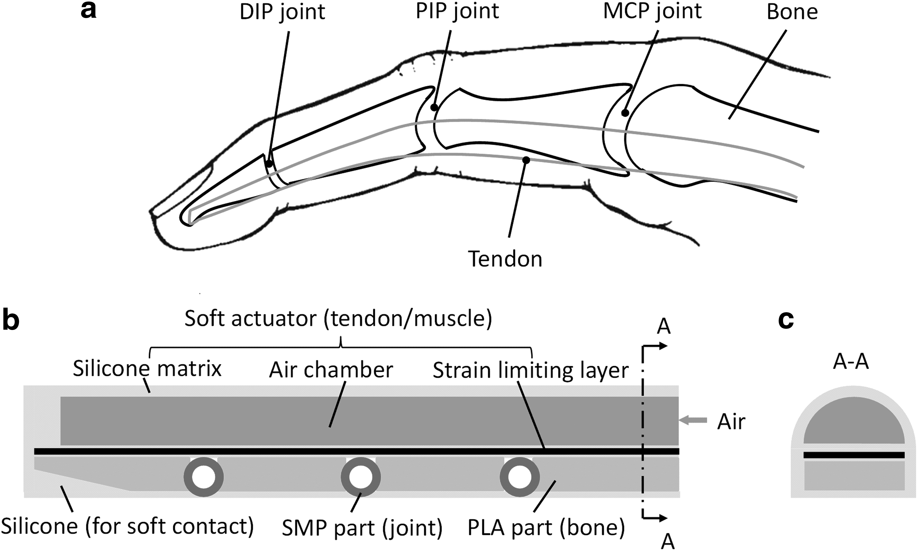
Numerous robotic designs are inspired by various creatures in the natural world. Human beings are good reference models for bionic design. Striated muscle on the human body can reversibly change its elastic modulus between 1 and 10 MPa. 24 For the proposed robotic finger in this study, inspiration is drawn from human finger, which exhibits variable stiffness property due to cooperation of tendon and muscle. A simple anatomic sketch of the human index finger is shown in Figure 1a. There are three joints, including the metacarpophalangeal (MCP) joint, the proximal interphalangeal (PIP) joint, and the distal interphalangeal (DIP) joint. Tendon transforms actuation from muscle to actuate the finger. Our proposed robotic finger design is shown in Figure 1b and c. Components mimicking different parts of the human finger are integrated into the finger design. The soft actuator is composed of a silicone matrix, air chamber, strain limiting layer, and reinforcement fiber (not shown in the figure). It provides the finger with bending actuation and acts like tendon/muscle. PLA parts act like bone segments in the finger and would enhance the finger's inherent stiffness in a rigid state. The three SMP parts act like joints in the finger due to their variable stiffness in a given temperature range. It can be noticed that the PLA part at the fingertip is chamfered to provide a large portion of silicone so that soft contact between the finger and an object can be achieved. The silicone layer serves as the soft skin as well as the soft actuation membrane. A transverse cross-sectional view A–A of the finger is shown in Figure 1c.
Bioinspired finger concept:
Compared with general fiber-reinforced soft pneumatic actuator 25 that has continuous bending as in Figure 2a (reinforced fiber is not shown for simplification), the proposed finger in this study shows segmented bending shape when all three SMP joints are heated above Tg as shown in Figure 2b. The soft actuator can only bend at the joints due to their weaker stiffness. There are also other means to realize segmented bending in soft actuators such as selective addition or elimination of the strain limiting layer 26 and adding sleeves. 27 However, these segmented bending actuator designs do not allow stiffness control. Apart from controllable stiffness, the proposed finger allows positional control because the stiffness of each joint is independently controlled. In contrast, soft pneumatic actuators as in Figure 2a have no control of curvature ρ (ρ is the reciprocal of soft actuator's radius r). That is, the curvature is always the same (except perturbed by other objects) at a given air pressure.

Bending shape comparison:
The compliance of the soft gripper and its adaption to objects' contour will ensure reliable grasping of objects. However, most soft grippers do not allow positional control, which is a drawback compared with articulated hand actuated by cables or motors, and so on. Looking at our human hands, we are able to control our finger compliance and finger posture to adapt to various grasping tasks. Therefore, it is desirable to have a robotic finger design that can mimic human fingers with both joint stiffness variation and posture control.
In Figure 3a and b, we have compared the grasping of a traditional soft gripper and the proposed gripper. In Figure 3a, the soft gripper can partially adapt to the object shape, but the contact between the finger and the object is not complete. This is because soft actuators without position feedback have uncontrollable curvature ρ. A good contact will only occur when the soft finger's bending curvature happens to be the same as that of an object's contour. Since the soft finger design in this research can control its posture owing to independent joint rotation control, the proposed gripper can be controlled for grasping of objects as in Figure 3b and c with good contact. Of course, the contact between the proposed gripper and objects' curved surface may not be as good. This happens to all articulated finger designs.

Benefits of proposed finger design:
The detailed structural design of the variable stiffness substrate is shown in Figure 4. The cylindrical sleeves are made of SMP material and serve as the finger joints. Ventilation slots on the side of the SMP joints are aimed to promote heat dissipation of pin heaters that will be inserted into the sleeves. A special feature of the substrate is that the connection between the SMP joints and the PLA segments is realized by interlock as shown in Figure 4. By embedding some parts of the SMP joints into the PLA segments, discrete parts (bones and joints) are firmly connected as an integral substrate. Manufacturing of these embedded interlock features is quite difficult, especially with SMP materials. In this research, they are fabricated successfully using the 3D printing facilities previously developed by the authors, which will be explained in the Fabrication section.

Structural design of the SMP/PLA smart substrate. PLA, polylactic acid; SMP, shape memory polymer.
Except the property of drastic elastic modulus variation around its glass transition temperature, the other important characteristic of SMP, shape memory effect, is also utilized in our finger design as illustrated in Figure 5. In Figure 5a, shape fixing and recovery mechanisms of one SMP joint are shown. After fabrication, the SMP joint's original shape (memorized shape) is set as in Figure 5a(i). By heating and deformation, the SMP joint is deformed to a temporary shape shown in Figure 5a(ii); meanwhile, the shape recovery stress is stored in the SMP joint. The stress has the tendency to bring the SMP joint to its original shape. However, the stress is unable to be released when the soft actuator is turned on. Once the soft actuator is turned off and the SMP joint is heated above Tg again, the stored shape recovery stress in the SMP joint will be released and the finger will be straightened. Figure 5b shows the role of SMP joints' shape recovery stress in the finger's shape restoration.

The finger's shape restoration property:
However, due to its small volume, the shape restoring stress of the SMP joint is not sufficient to recover to its original shape alone. It is, in fact, the combined spring force of the soft actuator and the SMPs recovery stress that causes the finger to return to its original position.
Analysis and Modeling
Reversible elastic modulus change in SMP has provided the proposed robotic finger with variable stiffness function. To quantify the finger's stiffness, theoretical modeling is performed in this section. Before modeling, the finger's stiffness k, which indicates the finger's capability to resist external force while maintaining its shape, is defined as follows:
where F is the applied force perpendicular to the finger's longitudinal direction at the fingertip and δ is the displacement at the fingertip caused by F. The proposed finger design is composed of a soft actuator and a variable stiffness substrate. To analyze the finger stiffness, stiffness of the substrate is calculated first.
To simplify the analysis, the PLA parts (bone segments) of the variable stiffness substrate are assumed to be absolutely rigid. This assumption is reasonable because the elastic modulus of PLA is much larger than the elastic modulus El of SMP below the glass transition region. The elastic modulus of PLA is around 3400 MPa,
28
while El of the SMP material used in this research is 1102 MPa in the glass state. Also, the PLA part's moment of inertia (due to large cross-section area in the design) is larger than the SMP part's moment of inertia, which makes the PLA parts harder to be deformed under the applied external force. Therefore, bending will mainly occur at the SMP joints under the above assumptions and the displacement δ is shown in Figure 6e when the finger's root end is fixed. From Figure 6e, δ is obtained by

Stiffness analysis of the finger:
where l1 is the length between two adjacent SMP joints' center and also the length between the center of SMP joint 3 and the finger's tip as shown in Figure 6d.
For an SMP joint i (i = 1, 2, 3), its shape changes from Figure 6a to b during the finger's deformation when the actuator is on. To obtain its deflection angle, the SMP joint is simplified using a cantilever beam as shown in Figure 6c. Deflection angle θi of the SMP joint i is as follows:
where l2 is the total length of one SMP joint part, Ia is the SMP joint's area moment of inertia. mi is the torque applied to the SMP joint i due to external force F and can be calculated by the following:
In this analysis, we have mainly focused on finger stiffness k when the finger undergoes a small amount of deflection (δ ≤ 5 mm). The reason is that a large deformation of the finger under an applied external load would lead to grasping failure especially when lifting and holding objects. Within the limited amount of deflection (δ ≤ 5 mm), θi has a relatively small value (total length of the variable stiffness substrate l0 is 120 mm in the fabricated prototype) and cosθ1 ≈ 1, cos(θ1 + θ2) ≈ 1, cos(θ1 + θ2 + θ3) ≈ 1. Therefore, mi can be approximated by
Es is the elastic modulus of SMP. From experimental results related to thermomechanical properties of SMP, Es varies dramatically within its glass transition region (Tg − Tw ≤ T ≤ Tg + Tw) and can be regarded as a constant outside the glass transition region.
29
In this study, we adopt the model proposed by Tobushi et al.
30
to obtain the relationship between SMP elastic modulus Es and its temperature T. Based on their model, log Es has a linear relationship with Tg/T (Tg and T are expressed by absolute temperature) and the slope is a as shown in Figure 6f. El and Eh indicate the values of Es below and above the glass transition region, respectively. The relationship between Es and T within the glass transition region is expressed as follows:
where Eg is the value of Es at the glass transition temperature. To simplify the analysis, we only consider the condition that three SMP joints are heated or cooled to the same temperature during temperature variation. The SMP materials used in the present study are processed from MM-type SMP pellets (SMP Technologies, Inc.) with properties of Tg = 318 K (45°C), Tw = 15 K, El = 1102 MPa, Eh = 3.8 MPa. With these parameter values and Eq. (6), we can obtain: Eg = 54.7 MPa, a = 26.03.
From Eqs. (3) and (5),
Then, the substrate stiffness ka can be derived from Eq. (7):
The relationship between the substrate stiffness ka and SMP joints' temperature T (Tg − Tw ≤ T ≤ Tg + Tw) is expressed by substituting Eq. (6) into Eq. (8):
Figure 7a presents the relationship between the substrate stiffness ka and the elastic modulus of SMP Es with the following parameter settings: l1 = 33 mm, l2 = 24 mm. It shows that ka is linearly proportional to Es. The relationship between the substrate stiffness ka and SMP joint temperature T is shown in Figure 7b. It should be noticed that ka is expressed in logarithmic scale in Figure 7b. We can see that log ka shows negative correlation with T.

Theoretical analysis:
Next, the stiffness of the soft actuator is analyzed. The effect of the braiding fibers on stiffness is neglected. The soft actuator is made of silicone rubber, a hyperelastic elastomer with nonlinear behavior. However, within a small strain, the stress–strain curve of silicone rubber is approximately linear (50% strain for Smooth Sil 950, 100% strain for Ecoflex 00-30).
31
Hence, we model silicone rubber as linear elastic in this stiffness analysis. The soft actuator under the application of external load is shown in Figure 6g and its stiffness kb is calculated by assuming it as an elastic cantilever:
where Er is the elastic modulus of the silicone rubber within the linear region and is obtained by linear fitting of the material's stress–strain curve, Ib is the soft actuator's area moment of inertia, l0 is the total length of the finger.
Finally, the finger stiffness is calculated by adding the substrate stiffness and the soft actuator stiffness as follows:
From this section, the idea of modulating the finger's stiffness by changing the SMP joints' temperature is theoretically proven.
Fabrication
3D printing of the smart SMP/PLA substrate
Design of the SMP joints shown in Figure 4 is interlocked with PLA parts, which makes the variable stiffness substrate difficult to be fabricated by traditional manufacturing methods such as injection/extrusion molding. However, easy fabrication of this multimaterial substrate is made possible by an in-house-developed multimaterial 3D printing capability. 23
Since no 3D printers can print SMP materials together with another material, the authors have to start with SMP filament fabrication. SMP pellets are processed to 1.75 mm standard filament by a corotating twin-screw extruder (PRISM TSE 16 TC). Fabricated SMP filament can then be used by an FDM 3D printer. Since SMP is a temperature-sensitive material, cooling system is added to the 3D printer (Makerbot Replicator 2X) to guarantee smooth 3D printing of SMP. Details of the SMP 3D printing process are presented in the authors' previous publication. 23 By 3D printing SMP and PLA simultaneously, interlock features of the SMP/PLA substrate are easily realized and no assembly procedure is needed. Crucial parameters related to the 3D printing process are listed in Table 1.
PLA, polylactic acid; SMP, shape memory polymer.
Figure 8 shows the fabricated SMP/PLA substrate by 3D printing. Raft below the fabricated model is necessary to ensure that there is enough adhesion force between the fabricated model and the build plate. The raft can be easily removed after 3D printing. Since the substrate has embedded smart materials (SMP) serving as finger joints, it is considered as a smart substrate.

3D printing of the SMP/PLA substrate.
Fabrication of the robotic finger
To integrate the smart substrate and a soft actuator into a single robotic finger, two molding steps are required as shown in Figure 9. The soft actuator in this study is made from a silicone rubber material EON-5 (cure time: 2–4 h, elongation at break: ≥360%), which was produced by the Shenzhen Yi-Heng Fine Chemical Co., Ltd. Inner air chamber of the soft pneumatic actuator is generated in the first molding step in Figure 9a. It can be seen that there are raised features on the walls of the top mold and bottom mold to generate a fiber path on the fabricated silicone rubber surface. The fiber path will ensure the fibers to be evenly placed on the soft actuator. In Figure 9b, three components that compose the finger are shown, including the rubber body wound by re-enforcing fibers, a sheet of woven material acting as the strain limiting layer, and the smart substrate. The second molding step is presented in Figure 9c to integrate the three components into one integral finger. The three components are placed into a larger mold in a specific sequence according to finger design in Figure 1. It is noticed that three small rods are inserted into the cylindrical holes of the smart substrate to reserve space for pin heaters before the second molding. The finger is fabricated as shown in Figure 9d after the second molding process. By removing the three small rods after the finger molding, pin heaters can be inserted into the finger as shown in Figure 9e. The upper mold, bottom mold, inner rod in Figure 9a, and the three small rods in Figure 9c are manufactured by 3D printing.
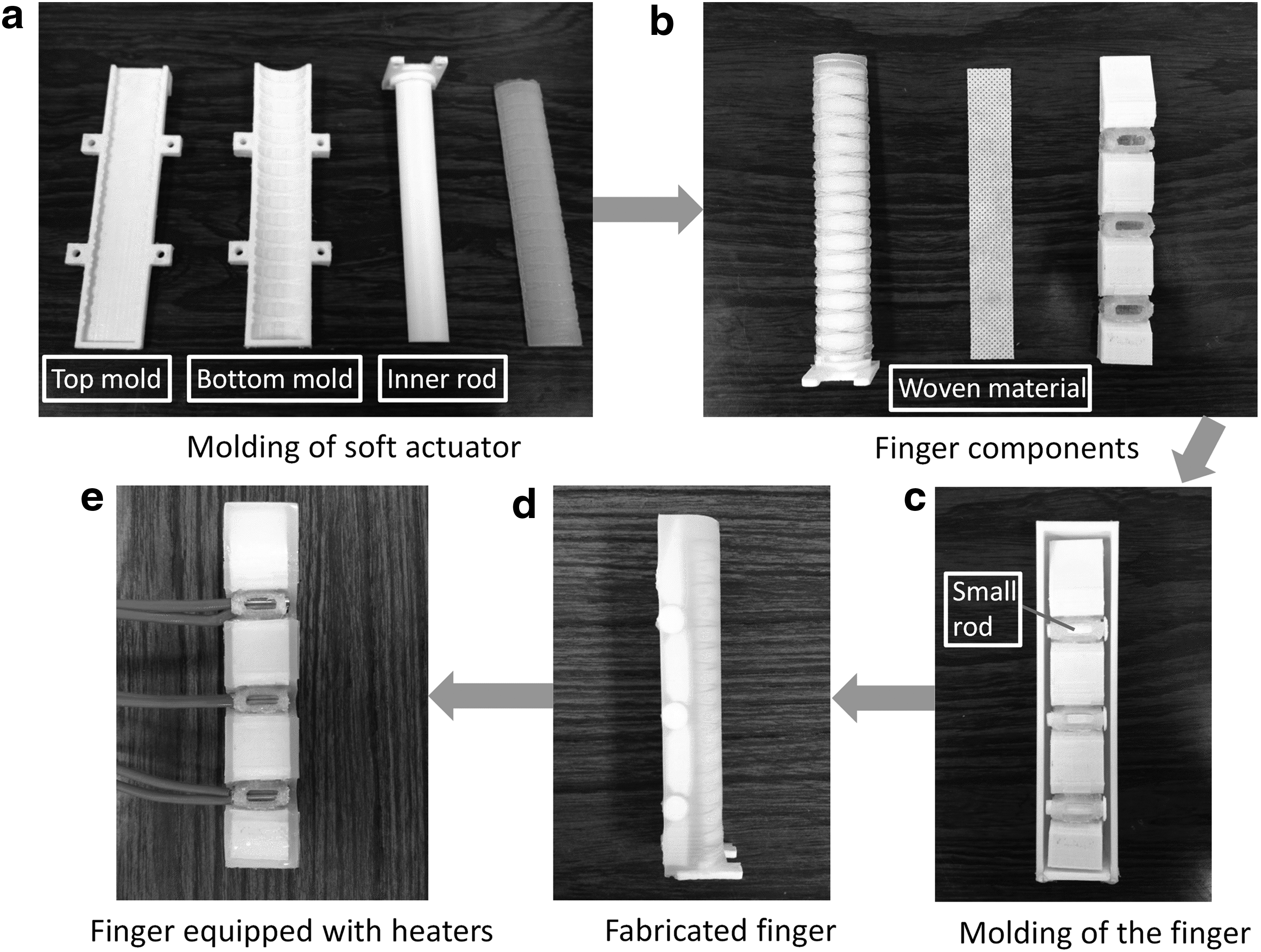
Fabrication processes of the variable stiffness finger:
Experimental Analysis
Finger position control
One of our design goals of the robotic finger is to realize bending shape control. First, a simple test to verify the bending shape given in Figure 2 is conducted. The fiber-reinforced soft pneumatic actuator shown in Figure 10a is fabricated with the same dimensions as the soft actuator used in the proposed variable stiffness finger. Both the soft actuator and the finger are pressurized up to 125 kPa while three SMP joints are heated to 50°C. In Figure 10b, the multisegment bending of the proposed finger is clearly shown, which is obviously different from the continuous curved shape of the soft actuator shown in Figure 10a. That is, the proposed robotic finger operates similarly to the human fingers.

Bending shape comparison:
Next, bending shape control of the finger by selective heating of SMP joints is experimentally verified as shown in Figure 11. The base coordinate system X − Y is established on the finger base and the origin is point “O” on the finger's root end. The finger's root end is fixed onto a platform with a specially designed fixture that has an air inlet. The finger's bending motion is captured by an HD camera.

Finger bending shape control by selective heating of the SMP joints:
Since there are three SMP joints in one finger, selective heating of these joints would create many combinations. In the tests, three selective heating modes are conducted, including (1) all three heaters on as in Figure 11a, (2) two heaters on and one heater off as in Figure 11b, and (3) one heater on and two heaters off as in Figure 11c. In all these tests, the selected SMP joints are heated up to 50°C. Internal air pressure p of the finger's soft actuator is controlled by a pressure control valve (IR1000-01; SMC Corporation). Figure 11 shows different bending shape of the finger in the three modes under two different pressures: p = 75 kPa and p = 125 kPa. At p = 125 kPa, the difference in finger's bending shape is very obvious for the three modes. A clearer comparison of the finger bending shape for the three modes (for p = 125 kPa) is presented in Figure 12. For mode 1, each joint has almost the same deflection angle. While for mode 2, joint 2 has a very small deflection angle since it is turned off. Mode 3 only shows deflection at joint 1 since only the heater on joint 1 is turned on. A video showing experiments with the three modes in Figure 11 can be viewed in Supplementary Video SV1 (Supplementary Data are available online at www.liebertpub.com/soro).

Comparison of the finger bending shape by selective heating of the SMP joints.
In fact, there are seven different combinations for selective joint heating in this finger (
The joint rotation control
A crucial property of the proposed finger is the individual control of each joint's rotation. By controlling a joint's rotation with air pressure and temperature (rigid or soft), bending position control of the finger can be accomplished, which is still a challenge for most existing soft fingers.
To investigate the joint rotation control, the bending deflection test is conducted. The experimental setup is shown in Figure 13a. During the test, only the middle joint is heated above Tg (T = 50°C). The bending motion is captured using an HD camera. For better measurement, markers are attached to the finger. During the test, air pressure is increased from 0 to 125 kPa with a 25-kPa interval, while the joint temperature is kept constant at T = 50°C. The test is repeated five times and average values are calculated. The relationship between joint rotation angle and air pressure is plotted in Figure 13b with standard deviation of each point shown in its vertical error bar. With the known joint angle–pressure relationship, bending position control of the finger can be achieved.

Individual joint rotation angle test:
Finger stiffness test
In this test, the variable stiffness property of the finger is experimentally demonstrated and the stiffness variation ratio is obtained. Based on the stiffness definition given in Eq. (1), the finger stiffness can be measured by the slope of the load–displacement curve. To test the stiffness of the finger, an experimental setup shown in Figure 14 is built. A digital force gauge (range: 0–10 N, resolution: 0.01 N) is fixed on a linear screw-driven guide, which can move in the vertical direction. The test finger is mounted on a platform driven by a linear guide in the horizontal direction. Both linear screw guides are controlled by stepper motors. During the test, probe of the force gauge is in contact with the fingertip and the displacement δ at the fingertip is controlled by the motor, ranging from 0 to 10 mm with an interval of 0.2 mm. At each displacement δ, the corresponding applied force F is recorded by the digital force gauge. Temperature T of SMP joints is measured by an infrared thermometer (measuring range: −50°C to 380°C, precision: ±1.5°C).

Stiffness test experimental setup.
Based on the proposed finger design, the finger stiffness can be determined by two main parameters: SMP joints' temperature T and soft actuator's inner air pressure p. These two parameters should both be taken into consideration when designing the experiments. Full factor experimental design is adopted in this test with temperature T settings: 20°C (room temperature), 45°C, 50°C, 55°C, and 60°C. At each temperature T, air pressure p has four settings: 0, 40, 80, and 120 kPa. Thus, 20 sets of experiments are conducted in total, and each set is repeated four times. Average values of recorded force are calculated and experimental results are presented in Figure 15.

Experimental results of the finger stiffness tests:
As shown in Figure 15, force–deflection curves are almost linear at the deflection range 0–2 mm. Finger stiffness with small deflection is of the most concern in this study as analyzed in the Analysis and Modeling section. Therefore, linear fitting is conducted for the displacement range 0–2 mm by the least square method, and the slope of the fitting line is the finger's stiffness value k. In Figure 15a, k11/k15 = 24.92, which means that finger stiffness at 20°C is 24.92 times of the finger stiffness at 60°C when soft actuator's air pressure p = 0 kPa. It is also observed from the figure that the finger stiffness has only a small change for SMP joint temperature change between 50°C and 60°C. This suggests that the SMP joints should be heated up to 50°C in practical use. Higher temperature above 50°C has only a minor effect on joint stiffness. The temperature (50°C) will not cause any pain even if the finger is in contact with a human user. Besides, heating the SMP to 50°C rather than 60°C is also time and energy efficient. During the test, we have found that the time required for temperature increase from room temperature 20–60°C is quite long (∼1 min for heaters at 2 V voltage). Therefore, we decide to preheat the SMP joint to 40°C to accelerate the stiffness variation control. It is found that heating SMP joints from 40°C to 50°C only takes about 7 s with the same heater setting. By increasing the power supply to heaters, the heating time can be further reduced to a couple of seconds, thus making it suitable for practical applications. In this study, it is suggested that the temperature control range of the SMP joints be set to 40–50°C. Figure 15b–d also indicate large stiffness variation below and above SMP glass transition temperature (45°C) at various air pressures of the soft actuator.
To show both pressure's and temperature's influences on finger stiffness and to verify possible cross interactions between these two parameters, the relationship between the finger stiffness k versus temperature T is plotted in Figure 16 based on data in Figure 15. It shows that the patterns of stiffness change against temperature T under each pressure p are consistent. Nevertheless, the stiffness variation ratio at p = 0 kPa (k11/k15 = 24.92) is larger than at p = 120 kPa (k41/k45 = 11.07). The stiffness variation ratio is decreasing with air pressure's increase. This could be explained as that the soft actuator's inherent stiffness is low at p = 0 kPa and its impact on the whole finger stiffness is quite small. While at p = 120 kPa, the stiffness of the soft actuator itself has increased significantly that it takes up a considerable proportion of the overall finger stiffness.

Finger stiffness versus temperature at different air pressures p.
From the above experimental results, it can be seen that the air pressure makes a considerable difference to finger stiffness, especially when the air pressure is high such as p = 120 kPa. Therefore, the theoretical analysis is only compared with experimental results at zero air pressure, that is, p = 0 kPa. Referring to Figure 17a, the theoretical stiffness values of the finger have the same variation tendency with the experimental values. Since stiffness values at high SMP joint temperature are relatively small, Figure 17b is plotted with finger stiffness expressed in the logarithmic scale to make the comparison more intuitively. The theoretical values show that the variable stiffness substrate's ratio in the whole finger's stiffness becomes smaller with a temperature increase. At 20°C, the finger stiffness is dominated by substrate stiffness. While at 60°C, the soft actuator's inherent stiffness plays a major role in the finger stiffness.

Calculated finger stiffness versus experimental results (p = 0 kPa):
Gripper grasping demonstration
A simple gripper assembled using two proposed fingers is built to demonstrate the finger's application in practical use. The assembled gripper is mounted on an X−Y stage as shown in Figure 18. The gripper can move in the X and Y direction. All heaters on the gripper are connected to a DC power supply. The object used for grasping is a roll of copper wires weighing 0.5 kg.

Assembled gripper grasping platform.
Figure 19 shows the grasping process of the gripper in two tests: one with variable stiffness and one without variable stiffness. In Figure 19a(i), the gripper is at rest with all heaters turned on (T = 50°C). Then, the gripper bends to grasp the object by increasing air pressure p from 0 to 125 kPa as in Figure 19a(ii). After the gripper reaches the grasping position, all heaters on the gripper are turned off and the SMP joints are cooled below Tg by an air fan for 10 s. Then, the gripper lifts the object steadily and moves to another location. We can see from Figure 19a(iii) and (iv) that deflection at the fingertip of the two fingers is relatively small before and after the lift of the object. This is due to the fingers' high stiffness at low temperature.

Grasping demonstration of the variable stiffness gripper:
In contrast, grasping test 2 in Figure 19b shows grasp and lift of the object with all heaters on throughout the test, meaning the gripper is always in a soft state. With the same air pressure p = 125 kPa, the gripper also bends to the grasping position but fails to lift the object up. From Figure 19b(iii), it is noticed that fingertips of the two fingers have large deflection under load and result in grasping failure as in Figure 19b(iv). The functionality of the variable stiffness of the gripper is demonstrated through these two grasping tests. A video clip showing the experiments can be viewed in the Supplementary Video SV2. In future research, the authors plan to further develop the proposed fingers into a bioinspired robotic hand with tactile sensors so that it can be used for service robots that need frequent interaction with human beings.
Conclusions
The controllability of stiffness and position is highly desirable in soft robotics for more reliable and predictable operations in practical applications. Most soft pneumatic robots have uncontrollable curvature and their stiffness variation is either impossible or cumbersome. In this article, we have addressed the stiffness control and position control in a soft pneumatic robotic finger via the application of a smart material substrate—made of SMP and PLA. By controlling the temperature of discrete SMP joints, the bending angle and stiffness of each SMP joint could be controlled independently. Enabled with variable stiffness and position control functions, the proposed soft finger design would broaden the applications of soft pneumatic fingers or grippers. In addition, fabrication of the smart material substrate is fast and efficient using an FDM 3D printer. The theoretical models provided insights into the relationship between finger stiffness and related parameters. Experiments were conducted to examine independent joint rotation control and position control abilities of the finger. Stiffness tests were conducted to quantify the finger stiffness variation ratio and the experimental results were compared with the theoretical results to verify the theoretic modeling. It was shown that the joint stiffness ratio can be 24.9 between the high stiffness and the low stiffness of the finger when air pressure p = 0. Grasping demonstration performed by the proposed gripper was also presented in the Experimental Analysis section.
The proposed robotic finger exhibits potential for precise bending position control because the joint rotation angles can be controlled. Thus, for future study, smart and simple joint rotation encoders will be added for joint rotation control so that more complicated grasping tasks could be performed. Besides, temperature feedback of SMP joints can be realized by adding mini-thermistors or thermocouples so that closed-loop stiffness control can be achieved. Furthermore, flexible pressure sensors could be added to the finger so that the gripper can be used for grasping operations of more diverse objects.
Footnotes
Acknowledgments
This work is supported by an HKU CRCG small project grant and an ITF grant UIM/268.
Author Disclosure Statement
No competing financial interests exist.
References
Supplementary Material
Please find the following supplemental material available below.
For Open Access articles published under a Creative Commons License, all supplemental material carries the same license as the article it is associated with.
For non-Open Access articles published, all supplemental material carries a non-exclusive license, and permission requests for re-use of supplemental material or any part of supplemental material shall be sent directly to the copyright owner as specified in the copyright notice associated with the article.