
Abstract
Abstract
Soft actuators with complex range of motion lead to strong interest in applying devices like biomedical catheters and steerable soft pipe inspectors. To facilitate the use of soft actuators in devices where controlled, complex, precise, and fast motion is required, a structurally controlled Omni directional soft cylindrical actuator is fabricated in a modular way using multilayer composite of polylactic acid based conductive Graphene, shape memory polymer, shape memory alloy, and polyurethane. Multiple fabrication techniques are discussed step by step that mainly include fused deposition modeling based 3D printing, dip coating, and UV curing. A mathematical control model is used to generate patterned electrical signals for the Omni directional deformations. Characterizations like structural control, bending, recovery, path, and thermal effect are carried out with and without load (10 g) to verify the new cylindrical design concept. Finally, the application of Omni directional actuator as a steerable catheter is explored by fabricating a scaled version of carotid artery through 3D printing using a semitransparent material.
Introduction
T
Soft actuators are also investigated for bio-devices especially for catheters55–58 because of their biocompatibility and easily controlled operation in wet situations. Catheters are very important because vascular disorders are treated by navigating these through the blood vessels using X-ray guidance. 58 Maneuverability, precision, stability, and low-cost fabrication are the key demands in catheters. Conventional catheters are operated using guide wires as per operator's skills. 56 Catheters with smart maneuverability control are studied, but they are unidirectional, bidirectional, or multidirectional with complex control. New design models of catheters using smart materials and soft actuators are still initial prototypes with lots of limitations, for example, a shape memory alloy (SMA) is used to bend catheter only in a single direction using thermal signal. 58 Thus, motion in confined environments is a big challenge that includes steering and positioning capabilities, limitations due to body shape changes, and obtrusive structural limitations. New actuator design using smart materials can result in the major evolution of such devices.
The goal of this work is the design, fabrication, and characterization of structurally controlled Omni directional soft cylindrical actuator that meet the current challenges of complex steering and precise motion in more conformal, unobtrusive, and compliant manner. The actuator is fabricated in a modular way using a multilayer composite of SMA, shape memory polymer (SMP), Conductive Graphene, and Polyurethane. The fabricated actuator can also retain its deformed state with zero power consumption which is a huge advantage. The design of Omni directional actuator consists of six functional layers in cylindrical form illustrated in Figure 1. The precise working principle of the actuator consists of deformations generated by four SMAs and SMP controlling the structure's state (hard/soft). The principle of retaining deformed state with zero power consumption is by changing the structure state from soft to hard in a deformed position.

Concept design of actuator.
The fabricated actuator is setup for testing in a rod cantilever form. To study the Omni directional movement, eight deformations are programmed using microcontroller. These eight defamations are 0° (Right), 45° (Diagonal Right Up), 90° (Straight Up), 135° (Left Diagonal Up), 180° (Left), 225° (Left Diagonal Down), 270° (Straight Down), and 315° (Right Diagonal Down). First positional and path of the deformations are studied and then a load of 10 g is attached with actuator in the suspended form to observe the deformation under load. The fabricated actuator showed excellent Omni directional deformation with and without load (10 g). It is believed that fabricated actuator might enhance the current devices' designs especially in catheters in cardiology and complex pipe inspection environments in the future. To validate this statement, a scaled version of carotid artery is 3D printed using a semitransparent material. The designed actuator was made to travel inside the artery first without controlled steering to recognize the error followed by controlled steering that resulted in smooth travel.
Materials and Methods
Shape memory experiment
To verify the shape memory property of 3D printable polymer, a strip (1 × 5 cm) was 3D printed and initially immersed in hot water (70°C) for 1 min. At this point, the structure of strip becomes soft and the shape of the strip can be changed using force. Strip is taken out of the hot water and deformed by hand force. The structure of strip becomes hard as soon as its temperature is lowered. At this point, no further deformation is possible by force or strip will break. Then deformed strip is again immersed into hot water and it automatically changes its structure to initial state (Supplementary Video S1; Supplementary Data are available online at www.liebertpub.com/soro). The temperature of SMP inside actuator is controlled using spiraled SMA on top of it.
Finite element analysis
To investigate and optimize the behavior of the Omni directional actuator, first the CAD model is designed in Solid Works 2013 (Supplementary Fig. S1) followed by importing mechanical model in ANSYS 14.0 to execute simulation. Homogeneous Brinson model of SMA is implemented for the prediction of stress and martensitic volume fraction distribution. For this model, an approximation of the behavior of a cantilever rod for small deflections was applied. However, the SMAs on the surface of the rod were acting in the domain of large deflection. For that reason, the model was solved as a nonlinear model. The structure is composed of a cylindrical rod on which a series of SMAs are aligned. Each SMA acts independently on the underlying section of rod. Different materials, including well-oriented polyurethane, were applied to the model. Following a mesh convergence analysis, the model was meshed and the elements correctly setup according to the element description. Displacement and strain are studied while symmetrically activating each SMA. A load of 10 g is applied to the tip of actuator in the downward direction and again displacement and strain are studied while symmetrically activating SMAs. The actuator wire is connected to a variable current source to deliver the heating current i(t). The value of current changes from 0 to 1 A with a step size of 1 mA. The dynamic model along with boundary condition is shown in Supplementary Figure S2. Material design parameters and their values are shown in Supplementary Table S1 (a) for polyurethane, (b) for conductive graphene filament, and (c) for SMA.
Omni actuator design and working
The design of Omni directional actuator consists of six functional layers in cylindrical form. First layer is conductive graphene layer, which is 3D printed in cylindrical form. The volume resistivity of this layer is 0.6 Ω-cm. Graphene is used as the core layer of the actuator because of its superior conductivity, improved mechanical properties, and easy 3D printing. The second layer is the SMP. This material is used because of its immediate change of state from hard to soft and soft to hard when temperature is increased and lowered, respectively. To control the temperature of SMP layer, the third layer is the SMA spiral onto second layer such that it covers all the outer area of the second layer. When signal is provided to the spiral SMA layer, the temperature of both layers increase; when the temperature reaches ∼70°C, the second layer, that is, SMP layer becomes soft. Using the external force, the layers at this point can be bent in any direction. When the applied external force is turned off, the second layer (SMP) recovers its initial state because of its shape memory property. Similarly, when the signal to third layer (spiral SMA) is turned off, the temperature of the actuator drops. When the temperature reaches close to 45°C, the second layer (SMP) changes its state from soft to hard and further deformation of the actuator is not possible even if the actuator is not back to its initial position from the deformed state. Because of this unique property of second and third layer material, our actuator can retain its deformed state with zero power consumption. The fourth layer is the dip coating of polyurethane. This layer is acting as an insulator between third and fifth layer. The fifth layer is the four SMAs that result in production of external force in Omni direction when signals are fed to them in a particular pattern. The sixth layer is the 3D printed polyurethane for outer protection layer from heat and to avoid short circuits.
Fabrication process
Methods involving simple 3D printing or restraining the SMA wires in a mold in which polymer is cured are not capable of manufacturing the actuator shown in Figure 1. Therefore, Omni directional actuator is fabricated in a modular way using multiple fabrication techniques (Supplementary Fig. S3). First conductive graphene rod is printed using commercial fused deposition modeling (FDM) based on 3D printing system. The conductive graphene filament is purchased from blackmagic3D. The cylindrical SMP is separately 3D printed using the same system after proper nozzle cleaning procedure. The graphene rod is manually inserted inside SMP cylinder, and SMA (BMF150) wire is spiral coated on top of SMP. Polyurethane is dip coated and cured using UV light. Four SMA wires (BMX150) are placed on top of polyurethane cylinder with phase difference of 90° with each other. Copper wires are soldered with each SMA wire and graphene rod. The graphene rod acts as a common ground for each SMA. For the top layer, Polyurethane cylinder is fabricated using UV curable 3D printer and manually aligned with the first part. The SMA wires embedded inside actuator are commercially available models by Toki Corporation, Japan. The functional parameters of SMA wires are shown in Supplementary Table S1. This actuator contains a larger number of design parameters, for example, the number, angle, and position of the SMA wires and the length, radius, and outer radius of the cylindrical-shaped actuator. The different parameters can be modified at different steps of the manufacturing process, which facilitates the customization of these different parameters. The proposed actuator is capable of Omni directional controlled deformation with zero power state hold capability.
Actuation setup and analysis
To control the input power and signal sequence, a custom electrical setup is built (Fig. 2). Three Agilent E3634A power supplies are used to power up the actuator with controlled current limits. A microcontroller by microchip (dsPIC3EP512MU810) is used to send the signal sequence through SMA drivers (mikroe) to the actuator. A thin-film-transistor liquid crystal display is programmed to display the real-time status of signals generated by the microcontroller. The Omni directional actuator is attached on a stand, and mechanical deformations are recorded using DSLR cameras. The thermal data of actuator are recorded using a thermal camera by FLIR connected with raspberry pi. IR temperature gun is also used to record the temperature data with digital values.

Experimental setup to test the actuation of Omni directional actuator. Actuator is fixed on a stand, and movements are recorded using a camera in front of actuator. The control signals are generated using a programmed microcontroller, which is sent to actuator through SMA drivers. Three power supplies with common ground are used to power the actuator. The current signal status is displayed on the TFT attached with microcontroller. TFT, (thin-film-transistor) liquid crystal display.
Image analysis
To measure the 3D deformation of the Omni directional actuator, image analysis was used. Two cameras were set at different positions for recording the deformation of Omni directional actuator during the experiments. Using an open source MATLAB program developed by Hedrick, the videos from the two cameras were analyzed to measure the bending deformation of the actuator (Supplementary Fig. S4). Before imaging actuator deformation, the image analysis program was calibrated to a set coordinate frame. This was done by creating a coordinate frame. The videos were analyzed in the program along with the calibration coefficient file (Supplementary Fig. S5). Three points at the free end tip were tracked in the videos to determine the deformation and twist of the actuator.
Results
Model analysis and layered structure design
SMA actuators, which have muscle-like functions of actuating and high power-to-weight ratio, have been very popular for artificial muscle (AM) design compared with traditional actuator-based AM, such as DC motor and pneumatic AM. The material composition of SMA (e.g., Cu–Zn, Cu–Zn–Al, Cu–Al–Ni, Ni–Ti, Ni–Ti–Fe, and Fe–Pt) largely determines the mechanical properties, including ductility, corrosion, and memory properties of the alloy. 59 Heating and cooling speed is the major influencing factor in generation of shape memory effect. 53 The fabricated actuator has two types of SMAs. One is known as BMF150 for deformations, and the second is known as BMX150 for heating the SMP layer. BMF150 is 40% extended from its real length using external force and when electric signal is introduced, it shrinks to its normal length. BMX150 don't need any extension before actuation. Both SMAs generate heat as well. Previously developed bending and twisting actuators rely on two SMA wires to induce the matrix into a twisting deformation. The bending movement generated by the SMA wires negates each other due to the opposite eccentricity where the twisting moment of each SMA wire is combined. Due to the linear positioning of the SMA wires in this type of design, the implementation of multiple SMA wires into a single actuator means that there are constraints in terms of the matrix shape, positioning of the SMA wires within the matrix, and the number of SMA wires. Due to the combination of these limitations, it would not be possible to manufacture an actuator that carries a load while being capable of outputting large deformations. 60
The Omni directional actuator introduced in this work is capable of circumventing limitations described above and generate controlled Omni directional deformations through the use of four twisted SMA wires at 90° to each other. The actuator in cylindrical form consists of composite in multiple layers, where Z axis corresponds to the length of the actuator. First layer consists of conductive graphene rod with volume resistivity of 0.6 ohm/cm. The length and width of graphene rod is 13 cm × 3 mm (Fig. 3a). The use of graphene layer as core material of actuator is because of its excellent electrical conduction, its deformability, and easy 3D printing. Second layer is polylactic acid (PLA) based SMP hollow cylinder. The SMP layer changes its structural state from hard to soft and soft to hard when change in temperature occurs. The 13 cm × 6 mm cylinder is printed using 3D printing system. The graphene rod is then embedded inside the SMP cylinder manually (Fig. 3b). To generate and control the heat for SMP, the third layer of BMF150 is manually coiled on top of SMP cylinder (Fig. 3c). When signal is provided to the third layer, the temperature of SMP layer (second layer) increases resulting in change of structural state from hard to soft. The Bending test is performed manually by hand to check the flexibility of three layers (Fig. 3d). A 2 mm polyurethane layer is coated on top of coiled BMF layer for introduction of insulation layer to avoid short circuit (Fig. 3e). Four twisted SMA wires (BMX150) are embedded on the top surface of polyurethane cylinder at constant eccentricity with a specific angle γ with respect to the Z axis such that the angle between the top and bottom ends of SMA wires is exactly 90° (Fig. 3f). Since the actuator is shaped as a cylinder and the four SMA wires are all positioned in parallel, the SMA wires simply need to be positioned at equidistance along the circumference of the cylinder. The graphene rod and all the SMA wires are connected to copper wire through soldered connectors. A final layer of polyurethane is applied resulting in completion of device fabrication. The diameter of each layer is named as the inner diameter (Dg), SMP diameter (Dsmp), SMA coil diameter (Dc-sma), Polyurethane diameter (Dp-1), four twisted SMA diameter (Dsma), and the outer diameter (Do), respectively (Fig. 1b).
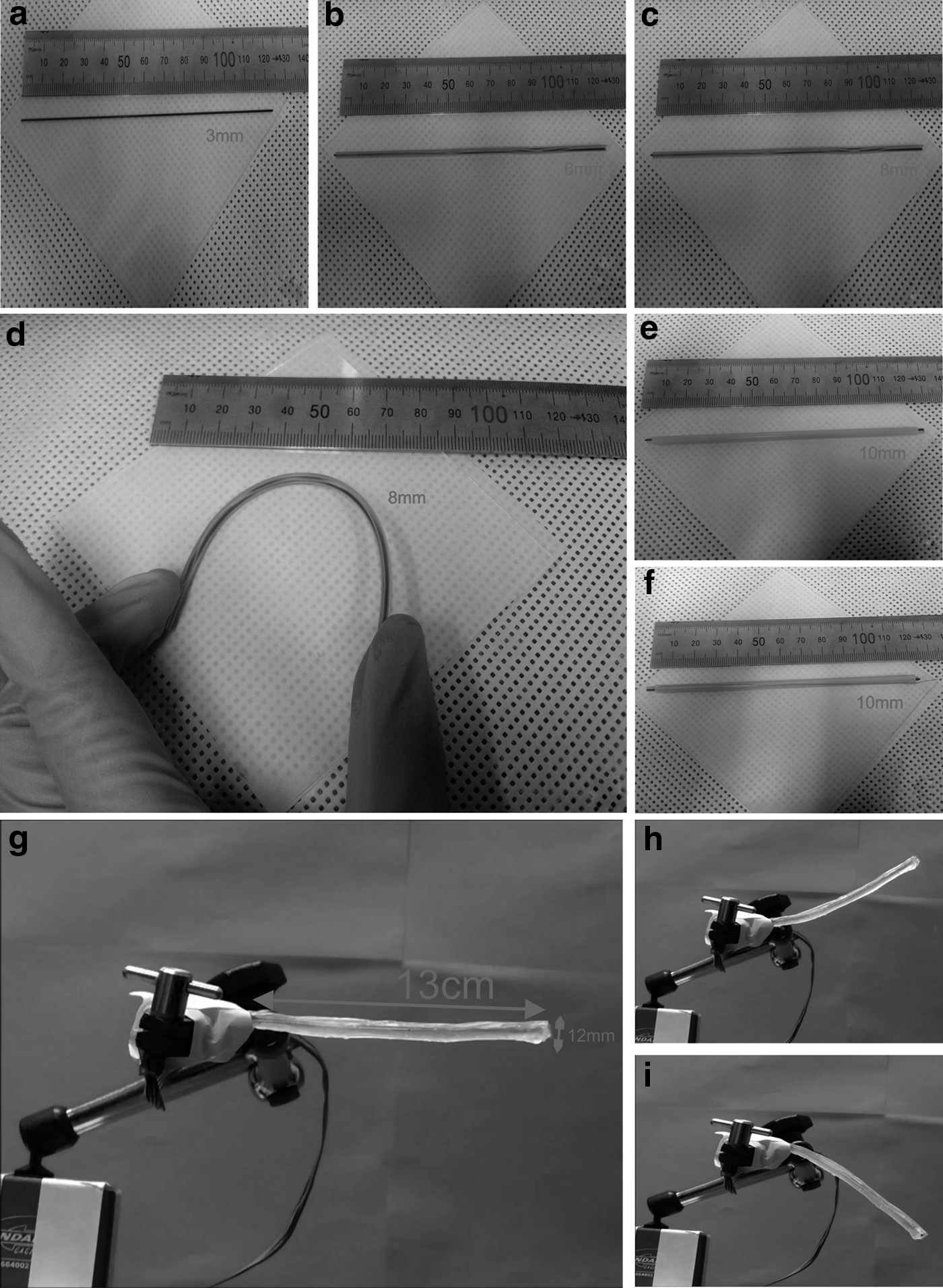
Step-by-step fabrication results of actuator.
Previously reported actuators 60 would require a PI or PID method to adjust the deformation angle of the actuator since there are only two SMA wires and both need to maintain a specific resistance lower than the fully actuated resistance. Although it could still be subject to overheating, the proposed control method does not require a feedback and parameter tuning. Moreover it does not run into risks of overshooting which would then require cooling of the SMA elements. Applying a fixed current is the simplest actuation method to attain intermediate deformation angles and does not require additional control methods, but it represents a trade-off between slow actuation with a low current and overheating by applying higher currents over a long period of time.
Since all SMA wires are controlled separately, the bending force of the actuator always adds up and the deformation movement corresponds to the sum of all the actuated SMA wires. Thus, the deformation angle actuation can be easily controlled by adjusting the signal of SMA wires to which current is outputted while always outputting the current required for full actuation.
To evaluate the performance of this type of actuator, its maximum deformation angle is evaluated and then a simple control method to attain intermediate deformation angles with zero power consumption is proposed and tested. The structural details of Omni directional actuator are shown in Figure 1. The SMA wires were connected in pairs so that an even number of SMA wires could be actuated. Each SMA wire is named as A, B, C, D, and E inside the actuator, whereas the graphene rod is named as G for common ground connection (Supplementary Fig. S1). Maximum deformation angle along with varying number of actuated pairs of SMAs is tested. A dsPIC microcontroller is programmed to generate the required signals for generation of deformation in eight directions. The actuator is attached with a clamper on a stand. Digital cameras are used to record the Omni directional actuation.
Actuator deformation control
Omni movement has been realized in several innovative ways, for example, by use of offset driving wheels, orthogonal wheels, 61 and surgical manipulators 62 and proved its efficiency in combination with its control models.
Fabricated Omni directional actuator consists of five SMAs as an active component. The motion in the structure is generated because of heat and contraction when signals are provided to these SMAs. The five SMAs are termed as A, B, C, D, and E, respectively (Supplementary Fig. S1). SMA-A is used to heat the SMP cylinder so that overall structure of actuator becomes soft and deformable. The contraction and relaxation of remaining four SMAs result in controlled Omni directional motion. The control equations consist of a simple vector addition technique. As the phase difference between top and bottom surface of a single SMA is 90°, each SMA when separately contracted results in generation of the movement @45°.
Figure 4a shows the SMA force vectors, that is, B, C, D, and E. Each SMA when actuated results in generation of a single force vector. Now to generate the deformation in a particular direction, addition of two actuator force vectors is required.

Mathematical model demonstration in vector form.
The full Omni directional movement is divided into four regions just like four regions of circle. First region covers the movement of actuator from 0° to 90°, that is, from right to upward direction. Second region covers the movement from 90° to 180°, that is, from upward to left direction. Third region covers the movement from 180° to 270°, that is, from left to downward direction. Fourth region covers the movement from 270° to 0°, that is, from downward to right direction.
Four basic deformation forces (up, down, left, right) are derived by addition of SMA vector forces (B, C, D, E). These forces are shown in Figure 4b and in equations below:
All the four basic equations for up, down, left, and right movement can be rewritten in a single equation form.
The standard stress of the actuator can be expressed as:
where
The strain of the embedded SMA in the y, z direction is then expressed in terms of the deformation in the same direction (ΔH) and of the
H0 is the original length of the actuator,
Omni position and path performance
The Omni directional deformation experiment is repeated thrice to verify the deformed angle value. To generate a controlled deformation on a specific angle, the SMA wires must be activated on a pattern. The time lapses of eight deformations (Supplementary Table S2) are recorded using a camera (Fig. 5a), and results from Finite element analysis are compared with each deformation (Fig. 5b). The maximum and minimum times in a certain directional deformation are 5 and 3 s, respectively. There is no additional load attached with the actuator during these experiments.

Time lapse of resulted actuation with finite element simulations.
Detailed analysis of position and path followed by Omni directional actuator is made using the image analysis on the recorded video during deformation experiments (Supplementary Video S2). The unique feature in our actuator is to maintain the deformed state with zero power consumption which is very useful and it will eliminate all the problems associated with continuous power signaling especially SMA heating problems. However, a small nonlinear positional error is observed when the actuator goes into deformed zero power consumption state. This is due to the time required by SMP (layer 2) to change its soft state to hard state when temperature is lowered. This positional error can be seen in Supplementary Figures S6b and S5(3) in the upward direction and Supplementary Figures S6d and S5(6) in the downward direction. This error can be removed by two methods. First, the initial angle of deformation is set to 1 cm ahead of desired angle. After deformation, the actuator goes into zero power consumption state. The error is calculated again in this stage. If there is no error, the desired operation can be performed; if there is still some error, the actuator is activated again to deform further in the same direction with the addition of error value and desired value. This method can negate the error in a single trial or multiple trails. Second, the actuator is tested in a virtual environment before the actual operating environment. In this method, the total time duration and desired angles are investigated first, and the new deformation values are gathered with minimum error value. Now these values are used to operate the actuator in real operation. This method does not need any correction of angle during the operation.
To get the actuation in upward direction, A, B, and C PWM signals are set high (Supplementary Fig. S6a). After actuator deformation to a certain level, SMA A is turned off first, which results in cooling of SMA A. When SMA A is cooled, the temperature of SMP cylinder drops down to room temperature linearly which results in changing the physical state of SMP from soft to hard material. In the next cycle both SMA B and SMA C are turned off resulting in the movement of actuator back to its original because of stiffness in the fabricated structure; but due to hard structure of SMP, the actuator maintains an angle of 6.8° (Supplementary Fig. S6b). This angle can be maintained for desired duration with zero power consumption. Similarly, when SMA A, D, and E are signaled up, the actuator deforms in the downward direction (Supplementary Fig. S6c) and after reaching a certain angle, the signal of SMA A is turned off and after one cycle SMA D and SMA E are turned off as well that resulted in deformed angle of −10.2° (Supplementary Fig. S6d). This deformed angle similarly can be retained for as long as required with zero power consumption. The value of current and voltage is set to maximum during this experiment which is 15 V, 1200 mA.
The actuator profiles in relaxed and fully contracted condition in all eight directions are observed using image analysis of deformation experiments (Fig. 6a, c, e, g, i–l). The highest deformation in the upward and downward direction is measured to be 3.49 and 5 cm, respectively. The radius of curvature increases significantly at the tip of the actuator. This is due to the fact that the end section of the actuator is only a seal which does not undergo any SMA actuation. The path followed by each point during contraction and relaxation in the Omni directional shows an interesting nonlinear behavior (Fig. 6b, d, f, h). A few observations can be made based on the actuator's motion. The path followed by the actuator during contraction is different from that during relaxation. The actuator contracts with a curved configuration. During relaxation the curvature decreases and the actuator extends to follow an outer path. The actuator builds up momentum during contraction and, therefore, keeps bending after the SMA wires have stopped contracting. The bumps in the positional data of the three trials are because of point tracking errors. This error occurs because of immediate color change or low color contrast at certain frame of the video.

Positional results of Omni directional actuator.

Payload effect on the actuator
To see the effect of a payload on the actuator performance, the maximum directional deformation with respect to time is measured with 10 g load attached to the tip of actuator in the downward direction with the help of a thread. The deformation experiment with payload is repeated thrice, and deformation time lapse in six directions are recorded using a camera (Supplementary Video S3). The time lapses of six deformations (Supplementary Table S2) are recorded using a camera (Fig. 7a), Finite element analysis model is updated with payload, and deformation results are compared (Fig. 7b).

Time lapse of resulted actuation with finite element simulations.

With payload, the actuator deformation decreases in all five directions, while deformation in the downward direction increases. This is because payload is helping the actuator by providing force in the downward direction thus addition of force by SMAs, as well as force by payload. In all other five directions, the payload has a negative effect which resulted in less deformation compared to deformation without payload. The actuator profiles in relaxed and fully contracted condition in the six directions are also studied in the similar manner as discussed in previous section (Fig. 7c–h). The highest deformation in the upward and downward direction is measured to be 2.37 and 7.55 cm. These results show that the payload mass has an effect on the actuation properties, but the design is able to perform well even with a nonsignificant payload mass and that it is possible to predict the effect of this added mass on the deformation of the actuator.
Thermal effects and durability
The thermal behavior of actuator plays an important role in the reliability of the actuator to use in different applications. The highest temperature inside the actuator is observed when it deforms in the upward direction with a 10 g payload on its tip. The temperature time lapse is recorded in this scenario to show the feasibility of actuator structure (Fig. 8). A patterned signal is provided to the actuator for deformation in the upward direction (Supplementary Video S4). The maximum temperature inside the actuator is close to 90°C. It is observed that critical temperature in each direction is reached under 5 s while temperature is lowered exponentially in ∼15 s (Fig. 9e).

Thermal camera time lapse of actuation in the upward direction. Color images available online at www.liebertpub.com/soro

Experimental results of Omni directional actuator.
Initially, the measurements are conducted to determine the maximum deformation of the actuators in eight directions with and without payload (Fig. 9a). This is done by driving the SMA with relatively high current until the deformation came to equilibrium. The condition for maximum deformation is set when no additional movement could be seen by inspection of the images. During these tests, a constant voltage was maintained across the SMA wires.
The actuator's length and its deformation magnitude are not closely related and very little change in the length of the actuator is observed during deformations (Supplementary Table S2). The temperature and the deformation are coupled rather than the voltage and the deformation; the cooling time might have an effect on the maximum actuation angle. Different voltage amplitudes are used to take the measurement for observing the effect of maximum deformation (Fig. 9b) and its recovery (Fig. 9c).
The percent of maximum deformation (Fig. 9b) is based on the angle of rotation achieved by a point in the upward and downward direction. Similarly, the percent recovery (Fig. 9c) is based on the initial position of the actuator at the beginning of testing. As the number of actuation cycles increases, the maximum deformation eventually reaches equilibrium. This equilibrium is achieved at different percent deformations for applied voltages of 12 and 15 V. As the driving voltage amplitude is increased, the equilibrium was found to be achieved over fewer cycles. Higher driving voltage amplitudes and number of cycles also mean greater residual heat and, consequently, the actuator recovery was reduced. Similar to the percentage maximum deformation, the percent recovery also reaches equilibrium faster as the driving voltage amplitude increases. Residual heat helps the actuators reach higher deformation, but causes hysteresis and delay in reaching the original position. The maximum deformation of 80% was achieved at driving current amplitudes of 700 and 1200 mA, leading to the conclusion that critical temperature is reached during each cycle, but heat dissipation is large enough that it restricts higher temperatures and thus the maximum contraction. Figure 9d shows the angle deformation in the upward and downward direction with different input currents with respect to time. The velocity of Omni directional actuator is also observed with and without payload (Fig. 9f). The maximum velocity of deformation is under 4 cm/s.
Application
The fabricated actuator showed the controlled Omni directional deformations in a cantilever rod based setup. To observe the usefulness and reliability of this actuator, it needs to be tested in a practical complex environment. Catheters in surgery need very delicate and controlled movements. Human arteries and blood vessels are sensitive and if there is any clogging then it is removed using medication or using catheters. Catheters are used for travelling through small holes to diagnose and to treat problems located in human arteries. Multiple catheter designs have been developed for controlling the movement of the catheter to provide better tools for doctors to diagnose and to treat the patient. Previous research on mechanisms of active catheters has focused on developing different mechanisms for bending and twisting. The bending mechanism is widely adopted in SMA-actuated catheters.10,63 However, this bending is not Omni directional which makes the movement of catheters difficult or sometimes impossible to move ahead in certain situations. 64
The fabricated actuator can be used as a new type of catheter to perform controlled Omni directional deformations for surgery. The actuator is not biocompatible, but it can be made biocompatible by dip coating the PDMS layer on the outer surface of actuator. The setup of the experiment includes a transparent scaled version of human carotid artery (Fig. 10a) fabricated using 3D printing system (Fig. 10b). The material used to 3D print the carotid human artery is a Natural PLA by 3DISON. The purpose of using this material is its transparency so that actuator's deformations can be observed inside the artery. The artery is divided into two channels from the center, one with diameter of 3 cm (channel-1) and other with diameter of 1 cm (channel-2). The actuator is connected with a 2 mm steel wire for extra grip. This enabled a firm grip to manually drive the actuator by hand while steering is done by a control system. The control system consists of a microcontroller that sends patterned signals to govern the behavior of five SMAs of the actuator (Supplementary Fig. S1). The structure of Omni directional actuator is soft throughout the process as the soft bending helps to prevent injury in case of contact accidents.

Biomedical application of Omni directional actuator.
The soft actuator is forced inside the artery by hand. After its successful insertion into channel-1, undesired structural changes such as twisting and bending are observed because of irregular contact with walls of the artery. To further move the actuator, the force is increased that resulted in the blockage of actuator in channel-1. Similar undesired structural changes because of irregular contact with walls of artery made it impossible for the actuator to move inside the channel-2 of the artery thus creating a scenario where it is impossible to move ahead without controlled steering (Fig. 10c). Next, actuator is held stationary inside the carotid artery by hand and controlled steering is tested (Fig. 10d). After successful steering is observed, the actuator is again forced inside the artery by hand to travel inside channel-1 with steered structure. The steered structure resulted in the smooth travel of the actuator inside channel-1 and channel-2 (Fig. 10e) (Supplementary Fig. S7).
This proves that steering is the key aspect of catheters, and Omni directional steering is extremely helpful in complex situations where normal one dimensional or two dimensional steering fails. The deformation results (Supplementary Video S5) by fabricated actuator inside scaled human carotid artery are good enough for the foundation of further study related to its feasibility as a steerable catheter in future.
Discussion
In summary, a cylindrical Omni directional actuator is designed and fabricated in a modular way using a multilayer composite consisting of graphene filament, SMP, SMA, and polyurethane. The actuator demonstrated excellent controlled Omni directional deformations under two load conditions, that is, 0 and 10 g. Various deformation characterizations are performed which proved the actuator's efficiency in terms of displacement under load, temperature, and power consumption. The actuator's deformation can be controlled along with structure stiffness which makes it highly suitable for biomedical applications such as steerable catheters and industrial applications such as pipe inspection robots. Multiple techniques used to fabricate the Omni directional actuator include FDM based 3D printing, UV curable 3D printing, Dip coating, and manual assembly of parts. As an additional advance, a scaled version of carotid human artery is 3D printed using a semitransparent material and Omni directional actuator's performance as a controlled steerable device is tested. The actuator moved smoothly inside the two channels of artery with controlled steering. Further exploration of such Omni directional actuators to replicate devices with more enhanced and controlled structural deformations will likely accelerate the development of a new generation of smart actuators with unparalleled properties and functionalities.
Footnotes
Acknowledgments
This work was supported by National Research Council of Science & Technology (NST) grant by the Korea government (MSIP) (No. CRC-15-03-KIMM), International Research & Development Program of the National Research Foundation of Korea (NRF) funded by the Ministry of Science, ICT and Future Planning of Korea (No. NRF-2015K1A3A1A16002763), and The Ministry of Science, ICT & Future Planning.
Author Contributions
J.Z.G. performed the experiments and also wrote the article with the help of Y.J.Y. and K.Y.S. The analysis of the results and the final revision of the article were done by K.H.C.
Author Disclosure Statement
The authors declare no conflicts of interest.
References
Supplementary Material
Please find the following supplemental material available below.
For Open Access articles published under a Creative Commons License, all supplemental material carries the same license as the article it is associated with.
For non-Open Access articles published, all supplemental material carries a non-exclusive license, and permission requests for re-use of supplemental material or any part of supplemental material shall be sent directly to the copyright owner as specified in the copyright notice associated with the article.