
Abstract
Abstract
This article describes a class of robots—“arthrobots”—inspired, in part, by the musculoskeletal system of arthropods (spiders and insects, inter alia). Arthrobots combine mechanical compliance, lightweight and simple construction, and inexpensive yet scalable design. An exoskeleton, constructed from thin organic polymeric tubes, provides lightweight structural support. Pneumatic joints modeled after the hydrostatic joints of spiders provide actuation and inherent mechanical compliance to external forces. An inflatable elastomeric tube (a “balloon”) enables active extension of a limb; an opposing elastic tendon enables passive retraction. A variety of robots constructed from these structural elements demonstrate (i) crawling with one or two limbs, (ii) walking with four or six limbs (including an insect-like triangular gait), (iii) walking with eight limbs, or (iv) floating and rowing on the surface of water. Arthrobots are simple to fabricate and are able to operate safely in contact with humans.
Introduction
T
In previous work, we have explored entirely “soft” robots2–7 —structures molded with elastomeric polymers without rigid internal structures, and actuated pneumatically—as one approach to fulfilling the stated goals. The designs of those robots were based on ideas from cephalopod anatomy, if not actually on the body plans of cephalopods. The work we describe here starts with another class of invertebrates: arthropods—particularly, arachnids (e.g., spiders) and hexapods (e.g., insects). 8
As a group, arthropods are characterized by a tough, structural exoskeleton (composed of chitin and protein), 9 and flexible joints. The exoskeleton serves some functions that are not necessarily relevant to robots—for example, protection of interior organs, and prevention of evaporation of water from the organism—but it also serves as an attachment point and anchor for muscles, and provides structural support that facilitates locomotion of arthropods on land (and occasionally on water). The combination of a hard exoskeleton with flexible joints provides a useful starting point in the development of new kinds of robots because it enables arthropods to exhibit a much higher strength-to-weight ratio than cephalopods.
Many types of flexible and inflatable joints and muscles have been developed in the past as a route to cooperative robotics—these include hydraulic or pneumatic joints that use expansion, contraction (e.g., McKibbon actuator), or bending for actuation.1,10,11 While these actuators fulfill the characteristic of inherent compliance, most of these involve complex assemblies intended for use in rugged, industrial robots that are heavy and expensive. For more delicate applications, Lu et al. have developed a mm-scale, pneumatic micro-hand, which uses polymer-balloons to contract hinged-joints on a microfabricated silicon skeleton, and can manipulate, for example, capelin eggs and fatty tissue 12 or serve as eyelid retractors for intraocular surgery. 13 Despite their usefulness in manipulating small, soft objects, these actuators were developed as micro-electromechanical systems, which are fragile and difficult to scale beyond several mm.
In another work, Schulz et al. developed an eight-legged, pneumatic, robot with a body length of 40-cm and 24 degrees of freedom mediated by joints consisting of hinges actuated by paired, antagonistic balloons. 14 This robot demonstrated the scalability of arthropod-inspired design, but the hard (metal) components complicate the ability to have the robot physically interact safely around humans, animals, and delicate materials. In general, to our knowledge, previously reported robots have not possessed all of the characteristics set forth in this article: mechanical compliance, lightweight and simple construction, and inexpensive yet scalable design.
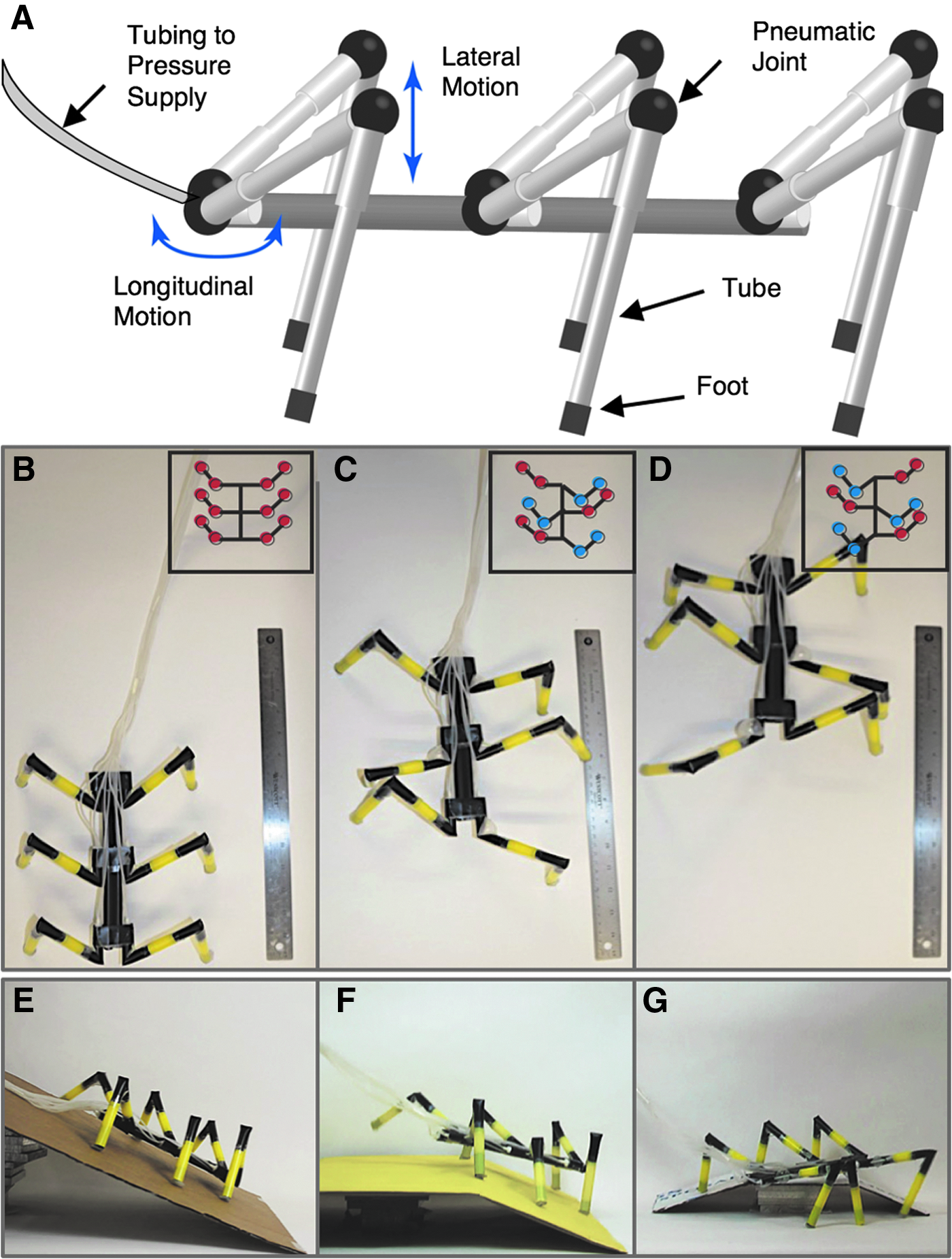
To develop a suitable type of robot, we took direct inspiration from the morphology of arachnids, which have complex legs (with seven distinct segments), but the mechanism by which they extend the joints in their legs is among the simplest used by arthropods.15,16 The basic structure of the leg joint of the spider (Fig. 1A–C) has four elements: (i) a flexible hinge that allows motion of rigid segments of exoskeleton relative to one another; (ii) a resting state in which the joint is folded; (iii) a hydraulic mechanism for extending the joint, which involves inflating a hydrostatic element in the joint, using muscles attached to the exoskeleton; (iv) an integrated muscle-flexor, which stretches as the joint extends, and which provides active force for its return to a folded state, when necessary.

Cross-sectional sketches comparing the anatomy of a spider joint to that of a spider-inspired joint and fabricated joints.
Methods and Design
Figure 1D–F sketches the arachnid-inspired joint that we designed and Supplementary Movie S1 (Supplementary Data are available online at www.liebertpub.com/soro) shows its operation. The details of fabrication are straightforward; we outline them in detail in the Supplementary Data. In brief, to assemble a pneumatic joint, we (i) cut a section of polypropylene tubing (drinking straws with diameters 7–11 mm) of the appropriate length for a leg; (ii) cut out one or several notches to define the positions and orientation of the joints; (iii) inserted a sealed length of narrow air balloon (coupled to small-diameter, silicone tubing to transfer gas) into the notch; and (iv) stretched a short elastomeric strip (the “tendon”) across the inside of the hinge region, with the joint folded, and fixed the ends of this strip to the tube with tape.
Figure 1F shows a sketch of an alternative joint that we designed to include a nonwoven, fiber-based, flexible sleeve to constrain the extent of expansion of the balloon, and therefore, to eliminate the risk of over-inflation and enable the use of static pressures, when necessary. The sleeved joints enable the exertion of greater force (when necessary) through use of pressures that would otherwise over-inflate an un-sleeved joint, but at the expense of more complex fabrication. Supplementary Figure S1 shows the steps we used to construct these joints. Supplementary Figure S2 shows an additional "stabilized" joint that we developed by inserting a folded tube into each joint to reduce out of plane bending of the hinge. We used these stabilized joints exclusively for our largest, eight-legged walker.
This spider-inspired joint is attractive as the basis for a new type of biomimetic robotic system for four reasons. (i) The basic element of an “exoskeleton” can be easily provided using lightweight tubes fabricated in commercial organic polymer. (Cylindrical beams provide the best strength-to-weight for bending in arbitrary directions.)17 (ii) Introducing a joint into this structure is accomplished easily by cutting a notch into the tube at the desired point of flexure. (iii) Using an elastomeric material for the inflatable actuator, rather than an inextensible material (e.g., polypropylene), allows the potential energy stored during elastic expansion of the balloon to deflate the balloon rapidly. (iv) Using an elastomeric tendon provides sufficient restoring force necessary to return an extended joint to its bent position when the pressure is release. By using passive, rather than active retraction, we can achieve actuation of a joint with just a single channel. By contrast, joints modeled on other types of arthropods, such as insects,18 require a pair of active, antagonistic muscles for both extension and retraction of joints, and therefore, at least two channels of actuation per joint.
Figure 1G–I shows a limb with two identical joints with relative axial offset of 180° and Supplementary Figure S3 shows a limb with a single actuated joint. Upon pressurization, the limb extends; upon depressurization, the stretched tendon restores the joint to the unpressurized, folded position. The maximum number of joints is limited by the physical dimensions of the parts: the interior diameter of the tube, and the external diameter of the tubing used to transfer pressurized gas. With larger tubes it would be possible to provide more actuators. These joints can be combined in series, and at any axial, rotational angle. Rather than using a hydrostat (which uses fluidic pressure) to apply the force required for motion, we inflate the balloon pneumatically, using low-pressure air (applied pressure P ≈ 70 kPa or 0.7 atm above atmospheric pressure). Pneumatic actuation has the advantages that air is light, it is essentially universally available, and it can be efficiently transferred from point to point through small, flexible, gas-transfer tubes located inside the polypropylene “exoskeletal” structure.
Results
Force characterization of single joints
Figure 2 shows the force exerted against a scale by extending joints versus the applied pressure. We determined a safe operating pressure of 70 kPa for un-sleeved joints and 200 kPa for sleeved joints. At higher pressures, the un-sleeved joint would experience a snap-through (over-inflation) of the balloon, while the sleeved joints tended to burst the polymeric tubing. A typical, un-sleeved joint pressurized at 70 kPA exerted a force of ∼200 mN, extended by ∼45°, and took ∼35 ms to extend and ∼45 ms to retract. A typical, sleeved joint pressurized at 200 kPA exerted a force of ∼1200 mN, extended by ∼70°, and took ∼65 ms to extend and ∼100 ms to retract (more reinforcement made the joints stronger, but slower). As a comparison, a hydrostatic joint of a spider can extend up to 160°. 9 The plane in which each joint moved was arbitrary (relative to other joints), but was fixed once the leg has been assembled. Repeated testing showed that un-sleeved joints could last for hundreds of cycles of extension and retraction, while sleeved joints could last for thousands of cycles until the rubber tendons snapped and require replacement.

Force exerted by sleeved and un-sleeved joints versus applied pressure. The un-sleeved joints experience snap-through instability beyond 70 kPa leading to the balloon to burst. Each point is a mean value of three measurements.
Efficiency characterization of single joints
The efficiency η of a joint characterizes the conversation of energy Qi input to each joint into useful mechanical work W. Although there is no single value of η for these joints that uniquely characterizes their performance—because their force transduction depends strongly on the type of robot and role that the limb plays in the gait—it is still instructive to estimate this quantity for a standard case. We estimated the efficiency by η = W/Qin, where
Figure 3 shows plots of the P − V hysteresis curves for seven consecutive cycles for both loaded and unloaded cases for both an un-sleeved joint (Fig. 3A) and a sleeved joint (Fig. 3B). The regular joint lifted the mass by h = 4.8 cm and yielded an efficiency of η = 1%; the remaining energy went into reversible expansion of the balloon/tendon (90%) or irreversible loss (9%). The sleeved joint lifted the mass by h = 6.0 cm and yielded η = 2%; the remaining energy went into reversible expansion of the balloon/tendon (76%) or irreversible loss (22%). Because most work goes into the expansion of the elastomeric elements, it can be decreased by optimized choice of polymer or by replacing the elastomeric balloons entirely with inextensible pouches that eliminate the reversible, elastic expansion of the balloon. This approach, however, could slow down the motion of a joint because the elastomeric tendon would have to perform all the work in the retraction phase.
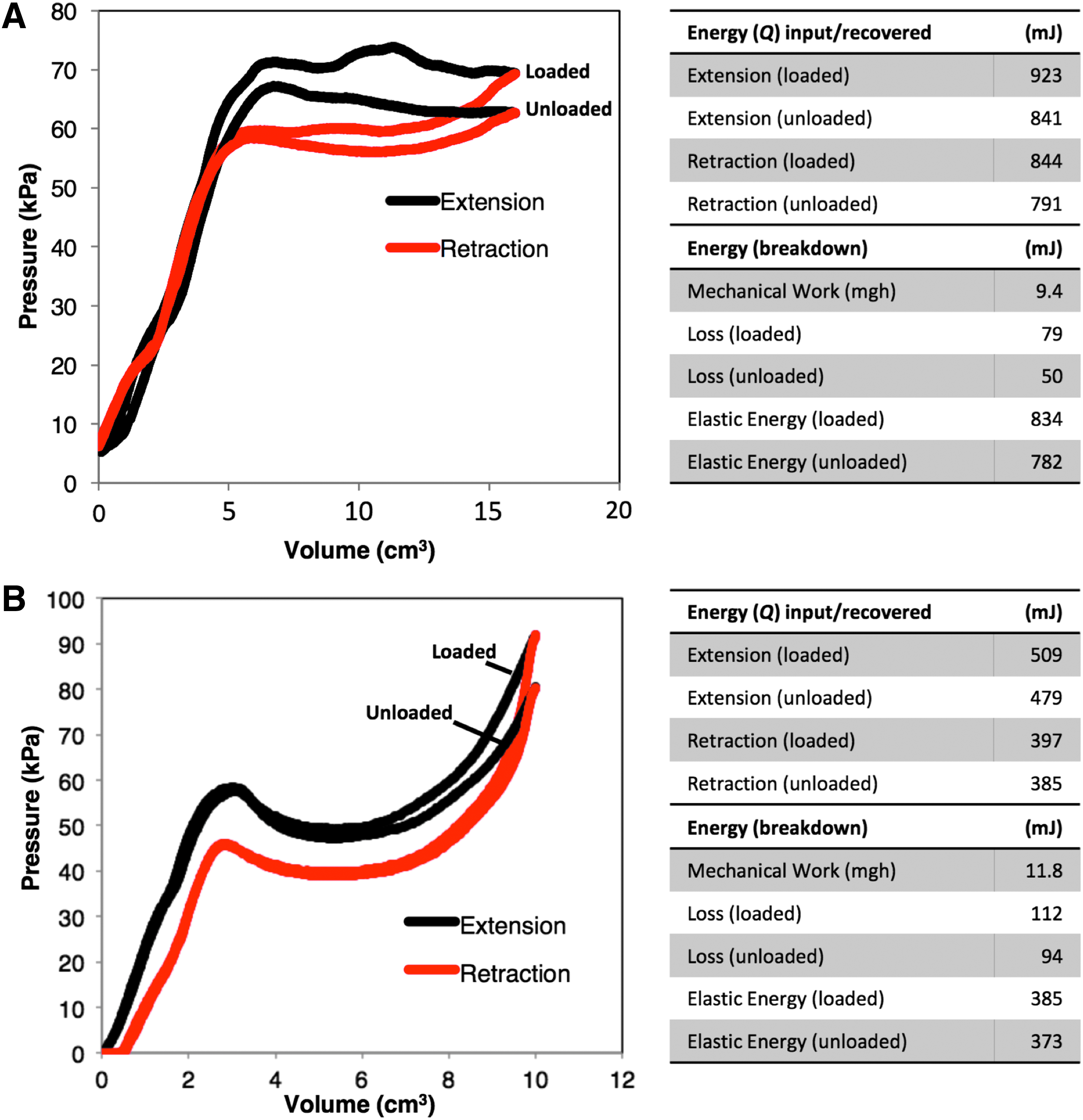
P–V energy calculations.
In general, the efficiency of inflation-based elastomeric actuators is low, 19 and is not only dominated by the work necessary to extend and/or compress the elastomer, but also depends on the strain, strain rate, and viscous losses due to turbulence and shear in the flowing gas. 20 Although the systems we have studied here were not designed to show high efficiency, other soft actuators relying on deflation rather than inflation, and operating at low strain, show thermodynamic efficiencies of 25–35%, which is comparable to human muscle. 21
Elementary crawling and walking arthrobots
To explore the opportunities and limitations of these joints, we developed several types of multi-legged robots, which we refer to as “arthrobots” because they (i) use a mechanism of actuation that is inspired, in-part, by the joints of spiders, and (ii) use gaits that resemble those used by different insects (specifically, the more advanced walking and rowing arthrobots). Supplementary Figure S5 and Supplementary Movies S2–S5 show the motion of some of the elementary crawlers and walkers that can be assembled using two to eight joints. Adhering the tubes together with hot-melt adhesive enabled the construction of a rigid “body” for the arthrobots. For example, to create T-type junctions, we cut a hole in the side of one tube, inserted the other, and secured the connection with hot-melt adhesive. Transparent polypropylene tubing (which is not always clearly visible in the figures) used for gas transfer connects each joint to an external source of pressurized gas through appropriate valves that control the timing of extension and folding of the individual joints.
Six-legged walking arthrobot
Figure 4 and Supplementary Movies S6–S8 show a six-legged, walking arthrobot moving over flat, irregular, tilted, and unsymmetrical surfaces. This arthrobot measured 20 cm long and weighed 38 g. Each leg had two degrees-of-freedom provided by two joints that were independently controllable. The range of extension and pattern of motion during each cycle of actuation was primarily determined by three factors: (i) the relative orientation of these joints, (ii) the pressure supplied to each joint upon activation, and (iii) the amount of restoring force provided by each elastomeric tendon (controlled by their length and position on each joint).
A six-legged, walking arthrobot.
Each cycle of motion starts with the leg in the “rear” position. To operate all 12 joints, we used a set of solenoid valves connected to an Arduino Due circuit board. An appropriate sequence of pressurization, implemented in Matlab (Mathworks), first lifted the leg from the surface, then moved it forward, down to the surface, and finally backwards to exert forward thrust. To enable the arthrobot to walk forward, we implemented a so-called “triangular” gate or “tripod” gait, which is a common gait used by six-legged insects 22 : first three legs (the middle leg on one side and the outer legs on the other, forming a triangular shape) move simultaneously, and then the remaining three legs follow suit. The triangular gait ensures a stable three-point suspension at all times during locomotion.
Eight-legged walking arthrobot
Figure 5 and Supplementary Movie S9 shows an eight-legged, walking arthrobot moving on a flat surface. This arthrobot measured 60 cm long and weighed 150 g. Like the six-legged arthrobot, each leg had 2 degrees-of-freedom (provided by a pair of independently controllable joints) to enable each limb to first move up (off the ground), then forward, down (back to the ground), and back (for forward thrust). For this arthrobot, we used sleeve-reinforced joints (Fig. 1F) for all 16 joints to enable (i) precise timing of actuation (by holding static pressures without over-expanding) and (ii) the use of sufficient pressures (∼200 kPA) to support the weight of the robot and enable it to progress forward. We attached additional “long” tendons (Fig. 5A) to the middle pair of legs to provide additional retracting force for extended limbs, and used stabilized joints to reduce bending out of the hinging plane for all joints.

An eight-legged, walking arthrobot.
To enable this arthrobot to progress forward, we implemented a gait that positions each limb, individually, into the forward position, and then moves all limbs back in unison. This gait ensured stable suspension at all times. In principle, more advanced gaits (including the ripple gait used by spiders) would be possible by independently controlling the flow rate to each joint. We include further details about the construction and locomotion of this arthrobot in the Supplementary Data.
Rowing arthrobot
Figure 6 and Supplementary Movie S10 shows another type of arthrobot that uses buoyancy to float and a two-limbed rowing action for locomotion across the surface of water. This arthrobot measured 50-cm across, weighed 25 g, and used the hydrophobicity of the exoskeletal tubes (increased by applying a thin layer of hydrophobic silicon grease to the tubing of the “foot”) combined with its natural buoyancy (the ends of the legs are sealed) to prevent the robot from sinking.

A rowing arthrobot. (
The middle pair of limbs performed a rowing motion while the front and back legs provided static support, buoyancy, and stabilization on the surface of the water. The middle pair of legs of this arthrobot consisted of two bending actuators angled at 90° relative to each other. One actuator produced a bending motion parallel to the surface of the water (joints labeled as B1 and B2 in Fig. 6), and the other produced bending in the direction orthogonal to the surface of the water (joints labeled as A1 and A2 in Fig. 6). This arrangement enabled the middle pair of legs to exhibit a rotational motion that was similar to the rowing action performed by the middle limbs of Gerridae (i.e., “water striders”).23–25 We used sleeved joints for these actuators to constrain the expansion of the balloons, and therefore, to enable the use of sufficient pressures (and therefore, force) to enable progressive movement. We include more details in the Supplementary Data.
Conclusion
This article demonstrates a simple strategy for constructing multi-legged robots that mimic some of the important musculoskeletal features of arthropods. Central to this strategy is an actuated, pneumatic joint that is loosely modeled on the architecture of the hydraulic joints of spiders. Arthrobot systems demonstrate opportunities to achieve four important objectives set for this class of robots. (i) They are very light, and generate a low surface loading. (The “water-strider” weighed 25 g.) (ii) The low cost of materials of construction, and the “in principle” simple construction, has the potential to lead to devices that are sufficiently inexpensive that they could be considered for one-time use. (iii) Despite their simplicity, the actuators are strong enough to support the mass of many-legged arthrobots yet versatile enough to yield sufficient degrees-of-freedom needed for a variety of gaits. (iv) These systems are clearly “cooperative,” that is, well suited for safe robot–human interaction. With low mass, compliant joints, and relatively slow motions, they do not have the momentum to be dangerous to humans, and will continue to be so even if substantially larger.
To demonstrate the capabilities and limitations of arachnid-inspired joints, we developed several types of crawlers and walkers, ranging from one to eight individually addressable limbs. Scaling our arthrobots in size, number of limbs, and style of locomotion, provided a unique set of challenges for each multi-limbed platform, and therefore, suggested different avenues for innovation. For example, transitioning from four-legged crawling to four-legged walking arthrobots required modifications in the relative angles of limbs and the sequence of actuation. Transitioning from four-legged, to six-legged, and then to eight-legged arthrobots each necessitated major changes in the gait because of the different distributions of weight and balance. We developed sleeve-reinforced joints to overcome the weight and force requirements of the eight-legged and rowing arthrobots.
These studies represent exploratory efforts to mimic some of the aspects of the mechanism used by arachnids to flex their legs. Although this work has not yet reached the phase of application, the relatively simple form of actuation suggests, however, that devices using a similar mechanism might function with simple controls (as pneu-net-based grippers are now well established).26–28 The integration of a light, semi-rigid structural element (the tube, which in this context is a cylindrical beam, with a high ratio of strength-to-weight) may make it possible to design legged “walkers” that function without the support of water (as required by many soft marine organisms), and are less cumbersome than the all-elastomeric systems we and others have already described.
There are many other opportunities for future developments. For example, one current challenge for these lightweight systems is progressive locomotion on smooth and/or inclined surfaces, due to a lack of sufficient traction. In the future, designing larger (heavier) robots and/or feet with greater contact area, traction, or weight could enable locomotion on a wider variety of surfaces. Another opportunity for improvement is to gain greater control over the exact kinematics of the forward and return stroke of a limb to implement, for example, the careful timing required for walking using a spider-like ripple gait. The nonlinear dynamics during balloon snap-through are difficult to control when using a compressible gas to inflate elastomeric joints. Using inextensible pouches instead of elastomeric balloons and/or hydraulics instead of pneumatics may eliminate the snap-through instability, enable greater force transduction, and allow for the bidirectional angular control necessary for applications that require precision in relative timing between limbs. Although helpful for precise control, these changes to the actuation mechanism would sacrifice weight and/or speed, especially for arthrobots with many joints.
Other advancements may involve use of (i) mechanically stronger components, including metal components, such as springs (in place of the elastomeric “tendon”) or aluminum tubes in place of the polymeric exoskeleton; (ii) higher pressures of gas that enable the transduction of higher forces; (iii) box beams or other analogs to exoskeletons. The elastomers that we have used are simply those with which we are familiar; a broad range of polymers with properties much superior to the polymers we have examined are available. In prior work focused on silicone-based soft, four-legged walkers, we have already demonstrated a strategy for ruggedizing a soft robot to upgrade it from a “tethered” robot (one with connections to an external pressure source and controlling valves) to an untethered one in which all components (a small, battery-driven compressor to provide pressured gas, along with valves and a microcontroller) are on board.28,29 Similarly, the use of support elements with greater rigidity and/or tougher elastomers may eventually enable the construction of autonomous arthrobots.
Footnotes
Acknowledgments
Work related to design of arachnid-inspired joints and exoskeletal structures was funded by the Department of Energy award #DE-SC0000989 through a subcontract from Northwestern University. A.N. and A.A.S. were supported by DARPA award #W911NF-11-1-0094. Y.Y.S. was supported by the NSERC Postdoctoral Fellowship award #PDF-421821-2012 and National Science Foundation award #IIS-11317744. A.A. was supported by a postdoctoral fellowship from the Swedish Research Council (VR). G.C., S.A., E.M., and C.Z. were supported by the NSF REU program under award #DMR-082048. Y.S. was supported by the Wyss Institute for Biologically Inspired Engineering at Harvard University.
Author Disclosure Statement
GM Whitesides is a board member of Soft Robotics, Inc., a company focused on commercializing soft robotic grippers. No competing financial interests exist for the other authors.
References
Supplementary Material
Please find the following supplemental material available below.
For Open Access articles published under a Creative Commons License, all supplemental material carries the same license as the article it is associated with.
For non-Open Access articles published, all supplemental material carries a non-exclusive license, and permission requests for re-use of supplemental material or any part of supplemental material shall be sent directly to the copyright owner as specified in the copyright notice associated with the article.