
Abstract
Abstract
Soft pneumatic actuators (SPAs), as novel types of motion drivers for robotic devices, excel in many applications, such as rehabilitation and biomimicry, which demand compliance and softness. To further expand their scope of utilization, the SPAs should be customizable to meet the distinctive requirements of different applications. This article proposes a novel perspective on the SPA working mechanism based on stiffness distribution and then presents a versatile method called stiffness customization and patterning (SCP) for SPA body stiffness layout as a novel attempt to customize SPAs with distinctive properties. We fabricated a hybrid type of material combining unstretchable material and silicone with customizable aggregated elasticity. The tensile results showed that embedding unstretchable material directly increases the stiffness of the hybrid material sample, and our stress–strain model for SCP is able to adequately predict the elasticity of hybrid samples with specific material ratios. By applying this approach to bending-type SPAs, we are able to mitigate SPA buckling, a main failure mode of SPAs, and improve the SPA tip force by using hybrid material with globally increased stiffness. We also diversify bending modalities with different stiffness configurations in the hybrid material. SCP offers numerous ways to engineer SPAs for more applications.
Introduction
S
Each specific application demands distinctive capabilities of SPAs. In finger rehabilitation, SPAs are required to produce large ranges of motion and force outputs.21,24,25 SPA-based soft grippers require the SPAs to be designed differently according to the tasks. For example, some tasks entail a secure grasp with strong force output, 26 while some tasks focus on grabbing objects of wide ranges of sizes and shapes.5,27,28
With the diversification of SPA applications, a multiplicity of methods has been developed to design SPAs with desirable properties. Regarding the force output, engineers mostly relied on stiffer materials, fiber/shell reinforcement, or enlarged chamber sizes to enhance the SPA tip forces.4,7,24–26 To diversify the SPA motion modalities, varied fiber winding patterns29,30 and shape engineering16,17 have been adopted to develop SPAs capable of achieving interesting and sophisticated motions and shapes. However, with all these different methods available, it can be confusing for engineers regarding the choices of the methods to design SPAs for their own needs and they each require different facilities for SPA fabrication. Sometimes, these methods have drawbacks in other aspects of SPA engineering. For example, silicones with high shore hardness (e.g., DragonSkin 0030) can be adopted to achieve high force outputs in SPAs; however, such silicone could hardly fill the whole space within the mold due to its high viscosity, which would eventually affect the quality of SPAs. Motion design based on shape engineering may result in irrational sizes for macroscale SPA and repeated mold preparation as shape engineering is highly dependent on dimensions for structural stiffness. Therefore, we believe that it is imperative to develop a highly versatile and effective approach that can tune different SPA properties.
The generation of SPAs is a transformative process from isotropic to anisotropic deformation by virtue of incorporation of materials with different stiffness. For example, the attachment of a strain-constraining layer (SCL) to one side of a hollow silicone body converts the radial inflation into a bending motion as the high stiffness of the SCL leads to unilateral elongation of SPAs. Winding fiber around the silicone body multiplies the material stiffness circumferentially and therefore generates a radial constraint to contain the SPA thickness during actuation. Furthermore, the global increase in the SPA material stiffness would result in higher force output. Taking the multimaterial-based SPA as a whole, the distribution of different stiffness throughout the SPA structure determines its properties. More significantly, the design of the stiffness distribution pattern allows huge possibilities in modification of the SPA properties. Literature review shows that there were few attempts made to tune the SPA properties through modifications of local stiffness within the SPA structure.27,31 Their work shed light on some unconventional modulations of the SPA bending modalities and motivated us to further explore more modulation possibilities through a thorough investigation into the fundamental working principle—stiffness distribution.
This article presents a stiffness customization and patterning (SCP) method to produce a hybrid material with customizable elasticity, which eventually can be utilized to design the stiffness distribution throughout the SPA body and thus regulate its properties, such as the force output and motion types. SCP32–35 combines two kinds of materials with different elasticities into a hybrid material with an aggregated elasticity determined by the material ratio. We also developed a fabrication method, which can adequately incorporate the SCP concept into the SPA and ensure repeatability and versatility in SPA production, as well as robustness in SPA performance. By applying SCP to our bending SPA, we managed to mitigate the SPA buckling issue and improve the SPA maximum tip force through global increase in the material stiffness of the SPA body and produce SPAs capable of achieving incremental curvature and helix shapes by distributing varied stiffness along the SPA body. This work aims to provide a better understanding of SPA engineering in terms of properties of modulation based on stiffness distribution in the SPA body and a highly versatile and effective SCP approach to achieve the different SPA property modulations and eventually facilitate SPA customization for various applications.
Stiffness Customization and Patterning
Proof of concept
Stiffness customization is generally achieved by combining multiple materials of different stiffness or structures into one composite structure,32–35 ultimately leading to a desirable stiffness in the composite structure, which can be used for shape adaptation or large deformation of aircraft wings especially in aerospace engineering. Our proposed SCP is a similar method applied to SPA engineering for the purpose of SPA property modulation. As shown in Figure 1a.i, we can combine two materials with different stiffness either in serial or parallel manner to make a hybrid type of material and use the material ratio to program the stiffness of the hybrid material as a result of spatially averaged effect (Fig. 1a.ii). Considering the SPA fabrication and the choices of the material, in the article, we only focus on the serial connection of the two materials. Eventually, we will use SCP to produce a layer of hybrid material with predesigned stiffness magnitude and pattern and combine this layer with a silicone bladder reinforced by dense fiber wall into an SPA of specific properties.

Concept of SCP and its realization.
Following the SCP concept, we chose fabric and hyperelastic silicone rubber—Ecoflex 0030 (EF30)—as the two components because these two materials can have a relatively strong bonding with the fabric mesh fully impregnated with EF30 prepolymer. Figure 1b shows the hybrid material sample design (dimension—80 × 20 × 2 mm3), in which fabric patches are evenly distributed along the silicone strip. To study the effect of material ratio on aggregated stiffness of the hybrid material, we chose to test samples with 20%, 40%, 60%, and 80% fabric embedding ratios (FERs), which correspond to two, four, six, and eight segments of 8-mm-long fabric patches, respectively. For detailed specifications of all the hybrid material samples, please refer to Supplementary Table S1 (Supplementary Data are available online at www.liebertpub.com/soro).
Fabrication of the hybrid material is rather straightforward, as illustrated in Figure 1c and Supplementary Figure S1. According to different FERs, sample molds were designed and three-dimensional (3D) printed with different numbers of slots for accurate positioning of fabric patches. For each slot, we stacked four layers of fabric patches prepared by an electronic cutting machine (CAMEO; Silhouette America, Inc.) to reach 2 mm thickness. With EF30 prepolymer poured and cured, the sample fabrication was completed and ready for test after demolding.
Results of tensile test and discussion
All hybrid material samples with varied FERs were tested on the INSTRON machine at the extension rate of 100 mm/min. According to the tensile test results in Figure 2, embedding of unstretchable fabric regulates the stress–strain curve with higher FERs resulting in steeper slopes of the curves. We also built an SCP model to understand the relationship between FER and elasticity curve, which is given in the Supplementary Data. Our model is able to reasonably predict the curve characteristics of samples with different FERs despite minor discrepancies. In addition, the gaps between samples with varied FERs and the nonlinearity of the curves can be reflected by the model.

Tensile test results of hybrid material samples with 8-mm-long fabric patches and their model curves. Color images available online at www.liebertpub.com/soro
All the samples in Figure 2 were embedded with 8-mm-long fabric patches, while we also fabricated and tested samples of the same FERs, but with 4-mm-long fabric patches and samples of 90% FER with 12-mm-long fabric patches (Supplementary Fig. S2). The comparison between all types of samples, given in Supplementary Figure S3, shows that results of samples with the same FER are fairly similar, meaning that varied spacing between fabric patches, ensuing from different numbers and dimensions of the fabric patches, has limited influence on the overall characteristics of the curves. For the rest of this article, we mostly utilized fixed 8-mm-long fabric patches with varied spacing to achieve desirable FER and stiffness, although changing fabric length can also result in similar outcomes.
Except modulation of the stress–strain curve trajectory, the proposed SCP has no effect on other properties of the hybrid material. For example, the maximum stresses of samples, determined unilaterally by the weak component, which is EF30, cannot be improved by incorporation of fabric.
Conclusively, SCP is a mechanical approach to program the stress–strain relationship of the hybrid material. More importantly, with the understanding of the relationship between FER and material stiffness, this method allows us to design hybrid material with desirable stiffness for unique SPA properties, which will be elaborated in detail in the following sections.
Modulation of SPA Property by SCP
Design and fabrication of SPA with incorporation of SCP
Currently, SPAs that are able to generate diverse motions, such as bending, extending, and twisting, have been developed for different applications.3,7,13–15,29,30 For demonstration purposes, we focus on the bending-type SPAs coupled with a hybrid material jacket in this research and investigate the effect of the hybrid material on the SPA properties, including the relationship between bending angle and pressure, the maximum tip force, and bending modalities.
Our SPA is designed as a combination of an inner tubular bladder (Fig. 3a) reinforced by high-density fiber winding (Fig. 3b) and an external jacket of hybrid material (Fig. 3c). The fiber reinforcement is to enable SPAs to withstand high pressure (>250 kPa), while the hybrid material jacket is to tune SPA properties. EF30, cotton fabric, and fiber are the main SPA materials. The total length of the SPA is 100 mm long with 50 mm at one side as the fixation segment, 10 mm at the other side as the cap segment, and the remaining 40 mm in the middle as the bending segment of the actuator. The SPAs of 100 mm length were used in bending angle and tip force measurements. Additionally, we also prepared 140-mm-long SPAs with 80-mm bending segment for illustration of novel bending modalities.

Design and fabrication of bending SPA.
Based on this design, we formulated a fabrication method that can easily incorporate the SCP concept and produce robust SPAs, which is illustrated in Figure 3d. A carbon fiber rod of 6 × 6 mm2 square cross section (Fig. 3d.i), as the air chamber template, and the 3D printed bladder mold (Fig. 3d.ii) were utilized to prepare the inner silicone bladder with 1.6 mm wall thickness. After the first demolding and trimming, the bladder on the carbon fiber rod was mounted on a customized winding machine for the fiber winding process (Fig. 3d.iii). To strengthen the inner bladder and final actuator to withstand high pressure, we applied two layers of fiber winding (0.1-mm-thick cotton fiber) with 0.4 mm pitch. The fiber-reinforced bladder (FRB) was then placed in a 3D printed template for fabric attachment (Fig. 3d.iv). We also applied fabric at the cap and fixation segment to disable bending in those regions. The initially attached fabric strips were wrapped around the bladder by two rounds, followed by the placement of the FRB with fabric into the jacket mold. After the second curing process (Fig. 3d.v), the whole body of our SPA was finished. One piece of fabric, as the SCL, was then adhered to one side of the SPA body to achieve the bending motion. With the sealing at the cap segment and tube connecting at the fixation segment, the whole fabrication process was completed.
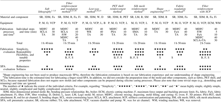
More details of the actual fabrication are illustrated in Supplementary Figure S4, and we also elaborated the benefits of our fabrication in the Supplementary Data. SPA fabrication has become fairly mature and diversified after years of development.1–10,16,17,24,31 In Table 1, we summarized the typical SPA fabrication techniques based on silicone rubber, including the required material, facilities, and processes, and compared the fabrications and their resultant SPAs in many aspects. Clearly, the benefits of our fabrication approach, including repeatability, versatility, and cost-effectiveness in the fabrication process and robustness in the SPA, outweigh its drawback of fabrication complexity and ensure its competitiveness among existing fabrication methods.
Tuning of bending angle versus pressure relationship of SPA
The results from the “Stiffness Customization and Patterning” section show that fabric embedding in silicone modulates the stress–strain characteristics of hybrid materials. Therefore, the hybrid material jacket around the SPA will alter the relationship between bending angle and pressure of the SPA. To investigate the effect, we measured the bending angle of SPAs with different FERs at different pressures using the measuring platform shown in Figure 4a. During the measurement, SPAs were supplied with compressed air with the pressure continuously increasing at the rate of 1 kPa/s by a motorized regulator. Three samples for each SPA FER were measured three times. All bending experiments were recorded and the videos were processed using a motion analysis program (Tracker, Open Source Physics) to measure bending angles of SPAs at different pressures displayed in the pressure sensor. In the case of the SPA with 80% FER, we stopped the measurement right after 160 kPa as the higher pressure will overstrain the hybrid material jacket, which breaks at 100% strain according to Figure 2.

Measurement setup and results of the angular displacement of SPAs.
All the averaged results with standard deviation (SD) are shown in Figure 4b, from which we can see that the higher the FERs are, the more pressure the SPAs require to reach a certain angle. For SPAs without fabric embedding, it takes around 28 kPa to reach 90°, while 40%, 60%, and 80% FERs require 36, 48, and 88 kPa, respectively. From the results, we can conclude that a global increase in the SPA material stiffness, achieved by SCP, makes SPAs less responsive upon internal air pressure. In addition, such bending pressure regulation has a ripple effect on the maximum tip force output, which is analyzed in the subsection “Improvement in tip force of SPA.”
To predict the SPA bending in free space and to understand the effect of the hybrid material, we also built a model based on the equilibrium between moments resulting from air pressure, material stress, and antibending force of the fiber, as shown in Equation S14. Detailed modeling is given in the Supplementary Data with the illustration of Supplementary Figure S5 and the modeling results are presented in Figure 4b. The comparison between the model and the measurement shows that the model is able to match experimental results to a large extent regardless of certain discrepancy in the case of 80% FER. More importantly, as we also considered the contractile force of the fiber along the SPA, the model can also follow the nonlinearity of experimental curves. With this model, we can design bending SPAs with unique curvature distributions.
Improvement in tip force of SPA
In this subsection, we first describe the yielding and buckling issues of the bending SPA, which will help us to redefine the maximum SPA tip force, and then explain how SCP improves the force output.
SPA as an energy body and its failing issues of force application
Due to the elastic property of the material, SPAs can be regarded as energy bodies. When pressurized, the bending SPA generates a curving motion with stretching of the material. The bending motion can be considered as an energy-storing process in the material body. Without considering the maximum applicable pressure, SPAs made of different materials can always store the same amount of energy, but at different bending angles. SPAs made of stiff silicone can store energy at relatively low bending angles as the material can store more energy per unit deformation. On the other hand, SPAs with soft material will need to bend substantially to store the same amount of energy. For example, with an input pressure of 40 kPa, our SPAs made of EF30 (modulus at 100% strain—10 psi) yielded higher bending angles (around 165°), while the SPAs with DragonSkin 0010 (DS10; modulus at 100% strain—22 psi) only balanced at about 30°.
When a force is applied to the tip of the bending SPA at the equilibrium of a certain pressure, the SPA will release the stored energy with reduced bending angle as the material relaxes when force enters the equilibrium. Ideally, the material shall relax evenly across the SPA body and the SPA unbends with uniform bending curvature (Fig. 5a.i). However, it is important to note that SPAs under load are actually subject to yielding and buckling. When force is applied to the tip of the SPA at relatively high bending angle and pushes the SPA tip back to its original position, the SPA will yield at the point that is subject to the largest moment generated by the applied force, which is, in our case, the proximal end of the SPA (Fig. 5a.ii). Moreover, if pressure is further increased to a certain level, the SPA will buckle with irregular deformation in the SPA body (Fig. 5a.iii, a.iv), followed by the SPA tip slipping off the force-applying object. The reason behind SPA buckling is explained as follows: given high pressure, the SPA would bend substantially in free space with high strain in the material. When the load forces the SPA tip to return to its original position, the moment ensuing from the load compresses the strained material in the axial direction, which reproduces column instability/buckling, but in a curved structure. The aforementioned failing theory of the force output of the bending SPAs can guide us to determine the actual maximum tip force of different bending SPAs and orientate us on how to improve the SPA forces.

The SPA force failing issue and force measurement results.
Force measurement and results
As the bending SPAs have yielding and buckling issues during force exertion, the maximum tip force is determined not only by the SPA dimension, applied pressure, and measurement condition but also by its failing mechanism. Force measurements of bending SPAs have been conducted in different ways according to prior arts,3,4,24,25 and the most popular measurement standard was to fix the proximal end and place the SPA tip against the load cell with a fixed wall supporting the SPA body. Such a method usually yielded high force outputs as the wall would minimize the functional length of SPAs (moment arm) and thus avoid the yielding and buckling issues. However, in actual SPA applications, force exertions barely occur in such confined conditions, which hardly justify the aforementioned measurement standard and undermine the reference value of the obtained results.
In our tip force measurement as shown in Figure 5a.i, we fixed the proximal end of the SPA and blocked the SPA tip using a load cell (20 N) with no structure supporting the SPA body between the proximal fixation and distal tip (50 mm). One wide plastic cap was mounted on the SPA tip to minimize the friction between the load cell and the SPA rubbery tip and also to evenly distribute the tip force on the load cell during the measurement. Such measuring conditions could fully expose the SPAs to the yielding and buckling issues and therefore reveal the real maximum force and highest applicable pressure. We measured tip forces of different SPAs with continuously increasing pressure (1 kPa/s) until the SPA tip slipped off the load cell. For each SPA type, we measured five samples and repeated the measurement three times for each sample. The force signal from the load cell and the pressure signal from the pressure sensor were recorded by data acquisition card (NI USB6003).
The averaged maximum forces and pressures of five samples for different SPA types are given in Figure 5b along with one of their representative force profiles. Detailed numbers of the force measurement are given in Supplementary Table S2. Initially, SPAs made of pure EF30 could only generate around 0.877 N before they failed at about 65 kPa. With the hybrid material jacket, maximum force outputs were improved manifestly with delayed failing points. For 40%, 60%, and 80% of FERs, forces of those SPAs can reach 1.18, 1.88, and 2.49 N, respectively, and their failing points were postponed to roughly 82, 134, and 191 kPa. The improvement in tip force is attributed to hybrid materials with elevated elasticities that enable SPAs to store higher energy with lower strain in the material and thus make the SPAs difficult to yield and buckle.
Interestingly, 40% FER only brings 0.3 N of improvement over the SPAs with pure EF30, while 60% and 80% FERs both made differences of around 0.6 N from 40% and 60%, respectively. The comparison between EF30 and DS10 SPAs shows that stiffer material can improve the force output as DS10 SPAs can reach 2.1 N, around 1.2 N higher than pure EF30 SPAs. On the other hand, EF30 SPAs of 80% FER have an average maximum force output higher than DS10 SPAs, proving that we are able to use hypersoft silicone rubber of low viscosity to fabricate SPAs that can produce force as high as that made of stiffer material. This feature can be very advantageous in occasions when low viscosity is needed for low defect rate in SPA fabrication and high forces are required for practical applications. Another difference is that force profiles of EF30-based SPAs and DS10-based SPAs follow varied paths with the former steeper than the latter, which probably resulted from difference in stress–strain characteristics between EF30 and DS10.
Diversification of bending modality of SPA
The proposed SCP allows us to implement regional stiffness design into the SPA jackets and hence diversify the SPA motion modalities. As a demonstration, we designed and fabricated two types of bending SPAs (Fig. 6 and Supplementary Video S1) that can bend into curves with incremental curvature and helix shapes with the fabric embedding pattern given in Supplementary Figure S6. However, as suggested by more pattern designs in Supplementary Figure S7, we can achieve more SPA motion modalities with SCP.

The bending SPAs of incremental curvatures and helix shapes.
SPA bending with incremental curvature
In the bending SPA with constant curvature, the hybrid material jacket design is an even distribution of fabric patches, which results in uniform overall elasticity along the material and constant bending curvature during the SPA actuation. By rearranging fabric patches with increasing spacing along the SPA body, we can formulate the jacket material with descending stiffness levels. During the SPA actuation, such jacket designs yield incremental bending curvature from the proximal to distal end. In our two incremental curvature SPA (ICSPA) prototypes, the spacing in between the fabric patches was designed into arithmetic series and geometric series, and their bending shapes are given in Figure 6a along with a constant curvature SPA (CCSPA) with the same FER as a comparison. Detailed spacing arrangements are given in Supplementary Figure S6a and b. From Figure 6a, we can see that constant spacing results in a uniform bending curvature, while the changing spacing in arithmetic series differentiates segmented curvature along the SPA body. A steeper change in spacing in the case of geometric series outputs higher increments in curvature change. Such curvature characteristics allow SPAs to grasp objects of a wider size range as ICSPAs, toward the distal end, can achieve smaller bending radii. As indicated in Figure 6a, the CCSPA could only reach a minimum diameter of 32 mm, whereas our two ICSPAs could go down to Ø22 mm in the arithmetic series case and Ø12 mm in the geometric series case, respectively. Figure 6b.i and b.ii illustrates CCSPS and ICSPA with spacing in geometric series grabbing the same circular object (Ø15 mm). Clearly, the CCSPA is unable to secure the grasp due to its large minimum bending radius, while the ICSPA can wrap around the object easily. Interestingly, the same ICSPA, given 90 kPa, is able to grip the mug handle and withstand its weight (400 g) (Fig. 6b.iii) by virtue of the reduced moment arm ensuing from the incremental curvature shape.
SPA bending as a helix
By shifting the SCL circumferentially, we can turn the in-plane SPA bending into a helical motion. Figure 6c shows three helix SPA prototypes with different SCL shifting step lengths (2, 4, and 6 mm, as shown in Supplementary Figure S6c) at one-, two-, and three-circle configurations. Every step of the SCL shift changes the bending direction of the SPA and thus avoids contact between the SPA tip and the proximal end. The continual multiple changes in the SPA bending direction eventually integrate into a helical curve. On the other hand, the larger the step length is, the more the bending direction changes and the larger the helix pitch is, which can be seen from the comparison between the three prototypes at the same amount of bending. Interestingly, to reach the same amount of bending, the helix SPAs of 2, 4, and 6 mm SCL shifting step lengths require different pressures. For example, to reach three-circle bending, they need 160, 140, and 120 kPa, respectively. The SPAs with helix type of motion provide solutions to more challenging grasping tasks as they can wrap around the object by more than one revolution, similar to a snake, to secure long and thin objects, as illustrated in Figure 6d.i. Furthermore, helix SPAs can also be used as contractile SPAs or soft springs in certain force applications. Therefore, we measured the length and the contraction ratio (ΔL/L) at their one, two, and three bending as shown in Figure 6c. As the 2 mm step length results in the smallest pitch, the corresponding SPAs have the largest contraction ratios with around 46% at three-circle bending. In the preliminary force characterization (Fig. 6d.ii), we measured the force–extension relationship of helix SPAs using a linear slide. All SPAs of the three helix types were measured at their two-circle bending configurations and results show that the SPAs of 6 mm step length exert the highest pulling force along the extension, followed by the SPAs of 4 and 2 mm step lengths. However, they are all able to yield a decent amount of pulling force ranging from 3 to 5 N, although at different extensions.
Conclusion and Future Work
Stiffness distribution is an important design factor of SPA engineering. By laying out the material stiffness across the SPA body, we can design SPAs with distinctive properties. In this article, we proposed SCP as a versatile method for design and implementation of stiffness distribution. From the fabrication, modeling, and tensile test of the hybrid material, we are able to control the stiffness of hybrid materials simply by the material ratio. More significantly, SCP allows us to arrange the stiffness distribution either globally or locally and thus offers a huge possibility in tuning the SPA properties, which has been demonstrated by our fiber-reinforced bending SPAs with hybrid material jackets. Through global increase in the jacket stiffness, we regulated the response of SPAs to the input pressure and, concurrently, elevated the maximum tip force of SPAs. In the case of 80% FER, the force outputs of our SPAs peaked at around 2.5 N with the buckling pressure postponed to about 190 kPa. In addition, we designed and implemented two types of stiffness patterns in the SPA jacket and, as a result, transformed the uniaxial bending and the uniform curvature of the SPA into incremental curvature bending and helical bending, which exemplifies the shape-regulating capability of SCP.
We believe that there are more interesting SPAs that can be designed, particularly in motion modalities, which can be further explored in the future. Moreover, other material combinations for SCP, such as combining fabric with stiffer silicone, are worth investigating as they have the potential to elevate the SPA force output to higher levels. Future works should also include the development of a design framework that can assist engineers to design SPAs with desired capabilities. Ultimately, SPA engineering based on SCP can potentially be one of the key solutions to customization of various SPAs and expansion of their application range.
Footnotes
Acknowledgments
This work was supported by an MOE AcRF Tier 2 research grant (R-397-000-203-112). The authors would like to thank Mr. Muhammed Abdurrahiem bin Abdul and the BioDesign Studio in Department of Biomedical Engineering at NUS for the use of INSTRON test machine and thank NUS Graduate School for Integrative Sciences and Engineering for providing scholarship support to the first and second authors of this article.
Author Disclosure Statement
No competing financial interests exist.
References
Supplementary Material
Please find the following supplemental material available below.
For Open Access articles published under a Creative Commons License, all supplemental material carries the same license as the article it is associated with.
For non-Open Access articles published, all supplemental material carries a non-exclusive license, and permission requests for re-use of supplemental material or any part of supplemental material shall be sent directly to the copyright owner as specified in the copyright notice associated with the article.