
Abstract
Abstract
This article experimentally investigates the potential of using flexible, inductance-based contraction sensors in the closed-loop motion control of soft robots. Accurate motion control remains a highly challenging task for soft robotic systems. Precise models of the actuation dynamics and environmental interactions are often unavailable. This renders open-loop control impossible, while closed-loop control suffers from a lack of suitable feedback. Conventional motion sensors, such as linear or rotary encoders, are difficult to adapt to robots that lack discrete mechanical joints. The rigid nature of these sensors runs contrary to the aspirational benefits of soft systems. As truly soft sensor solutions are still in their infancy, motion control of soft robots has so far relied on laboratory-based sensing systems such as motion capture, electromagnetic (EM) tracking, or Fiber Bragg Gratings. In this article, we used embedded flexible sensors known as Smart Braids to sense the contraction of McKibben muscles through changes in inductance. We evaluated closed-loop control on two systems: a revolute joint and a planar, one degree of freedom continuum manipulator. In the revolute joint, our proposed controller compensated for elasticity in the actuator connections. The Smart Braid feedback allowed motion control with a steady-state root-mean-square (RMS) error of [1.5]°. In the continuum manipulator, Smart Braid feedback enabled tracking of the desired tip angle with a steady-state RMS error of [1.25]°. This work demonstrates that Smart Braid sensors can provide accurate position feedback in closed-loop motion control suitable for field applications of soft robotic systems.
Introduction
T
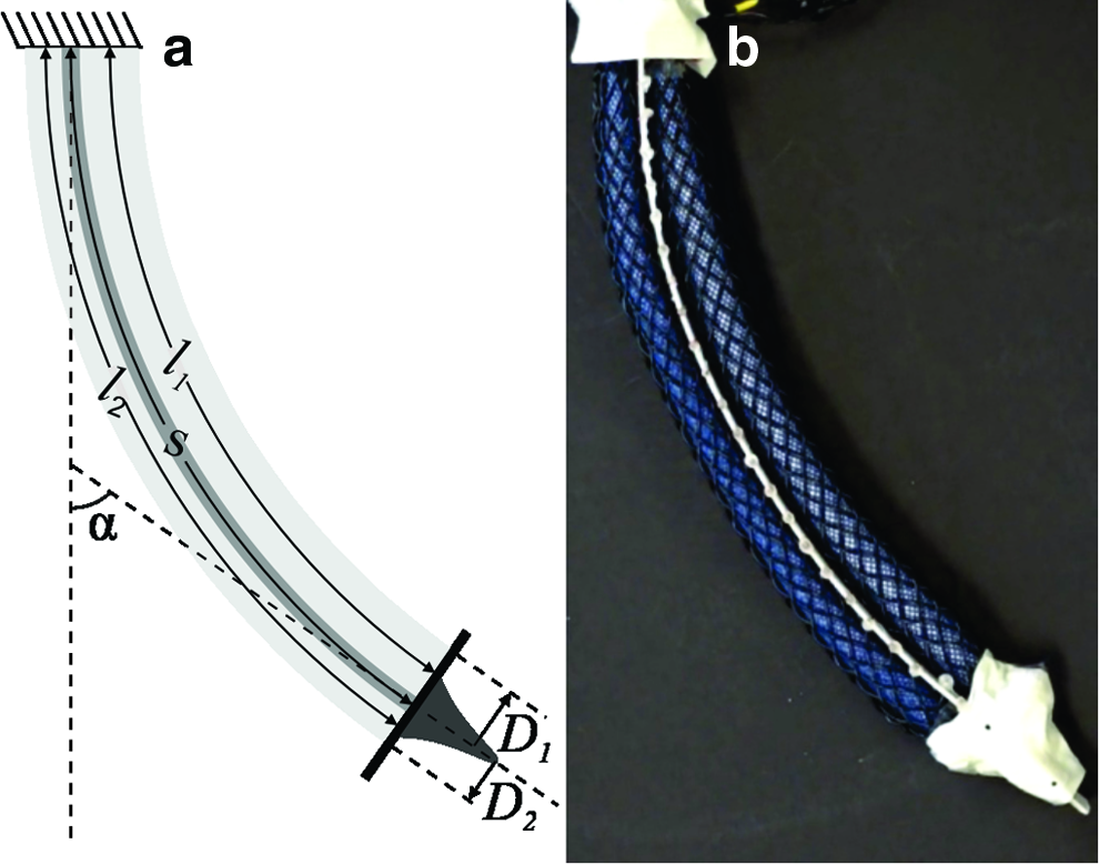
Despite recent advances, practical closed-loop motion control of soft robotic systems remains a challenge.12–14 The pose of many soft systems is difficult to measure with sensors common to rigid robots such as rotary and linear encoders. Soft robotic systems rarely provide convenient coupling points for such sensors. For example, the control of a soft, assistive device (Fig. 1a) might require sensing of human joint motion where the joint cannot be accessed directly. For a continuum manipulator, the problem is even more challenging, as motion is distributed throughout the entire system and no discrete joint axis exists (Fig. 1b).

Shown are two examples of soft robotic systems:
Current methods for sensing soft systems can be divided roughly into three categories: external localization, curvature sensing, and length sensing. External localization systems include, for example, camera-based 3D motion capture, which has been used to provide feedback for continuum manipulators,6,7 and an inflatable humanoid. 8 A similar technology is based on electromagnetic trackers.9,10 Curvature sensing is appropriate when soft robot motion corresponds to the bending of inextensible portions such as flexible “spines.” For such systems, a variety of curvature sensors exist. 15 For example, optical systems can measure curvature by measuring the attenuation of transmitted light.16,17 Other systems measure curvature through the Hall effect of a nearby magnet 18 or piezoelectric effects. 19
Finally, a soft robot's pose can be estimated by measuring changes in the length of paths along the continuously deformable structure. For example, one can measure the deformation of a continuum manipulator by measuring the displacement of inextensible strings alongside the lengths of the sections.20–23 A number of alternative sensors have been proposed to measure such changes in length. Fiber Bragg Gratings, for example, can detect strains in optical fibers. The strain changes the spacing of the gratings and the corresponding reflected wavelength. Groups of fibers can register curvature through changes in the fiber strains.11,24 These sensors have been used as feedback for the control of continuum devices.11,25–27 The strain measurable by these sensors is limited to the tensile strain that the optical fibers can undergo. A number of sensors are based on registering a change in electrical resistance under strain. The resistive element may be an elastomer28,29 and microchannels of conductive liquid30–32 or a conductive fabric. 33 Strain measurements can also come from the capacitance of specially formed “dielectric elastomers.”34–37 These elastomers can provide both actuation force and strain measurements through the changing separation of flexible electrodes. 38 In addition, we have shown in our prior work how inductance-based sensors can be used to measure the length of soft actuators.39–41
In this article, we used flexible sensors built into the structure of soft actuators to provide feedback for the motion control of two soft robotic systems. The first system was a revolute joint (Fig. 2). This allowed us to rigorously compare the efficacy of feedback from our sensors to that from a rotary encoder. This system is also an example of applications with a well-defined joint axis, yet in which the joint angle is difficult to measure, for example, in an assistive robotic device for an elbow or knee joint (Fig. 1a). The second system we tested was a planar, one degree of freedom continuum manipulator (Fig. 1b). This system highlights the ability of flexible sensors to enable the motion feedback control of systems without rigid joints.

A one degree of freedom revolute joint allowed us to compare two types of feedback control: one based on measurements from a rotary encoder and another based on measurements from Smart Braid sensors. The Smart Braid sensors used in this work were placed on top of an inner, nonconductive reinforcing braid (enlarged detail, black wires are conductive, blue fibers are polyester). A force transducer in series with the connection to the left actuator measured the tension in the connection cable. Color images available online at www.liebertpub.com/soro
The soft robotic systems that we evaluated were driven by McKibben muscles. McKibben muscles consist of an elastomeric bladder surrounded by a braided sheath.42,43 The braided sheaths used in this work shaped the expansion of the elastic bladder into a forceful contraction. McKibben muscles' soft nature and high force density have led to their widespread application in human-assistive devices.44–48 They have also been successfully employed in a range of continuum manipulators.20,49,50
In this work, the length of each McKibben muscle was measured through the inductance of a braided circuit that surrounded the actuator. As the actuator contracts, the inductance of the circuit increases. This increase in inductance is approximately linear with respect to the actuator length. 40 We refer to the circuit as a “Smart Braid” sensor. It is formed from off-the-shelf, insulated, conductive wires in a McKibben muscle pattern. 39 Smart Braid sensors do not require external cameras or antennas, and they are not limited to sensing the curvature of inextensible sections. They allow the length of the actuator to be measured without the additional force required to strain a self-sensing elastomer or the potential fragility introduced by optical fibers or strings.
The Smart Braid sensors used in this work were fabricated according to the process outlined in our previous work. 39 To improve the fatigue life of the sensors, the wires of the Smart Braid were isolated from the stress of actuation. This was accomplished by using an inner, polyester braid that reinforced the bladder against the internal pressure. The sensor braid was added over the top of this plastic braid. Both braids had similar fiber angles to create a similar contraction behavior.
This work presents the first demonstration of Smart Braid inductance sensors in the feedback control of robotic devices. Revolute Joint section includes the model, methods, and results of the revolute joint system. In this study, we propose a compensation method for compliance between length-sensing actuators (Smart Braid or otherwise) and the motion output. Continuum Manipulator section consists of a similar series of experiments on the continuum manipulator. Continuum Manipulator section also includes a model for Smart Braid sensors on continuum segments. Discussion and Conclusions section contains general discussion and conclusions.
Revolute Joint
The first example that we studied was a one degree of freedom revolute joint driven by antagonized McKibben muscles (Fig. 2). Smart Braid measurements of actuator length were used as feedback to control the joint angle. The controller actively compensated for the compliance in the actuator connections. The performance of this Smart Braid feedback controller was then compared to the performance of a similar controller that used feedback from a rotary encoder. This allowed us to perform a rigorous evaluation and comparison of the proposed Smart Braid feedback.
In the test fixture of the revolute joint, two Smart Braid McKibben muscles (Fig. 2) rotated a load by steel cables and a pulley with radius r = 25.4 mm (Fig. 3). The torque τ exerted on the load by the actuators was proportional to the difference between the two antagonized actuator forces, F1 and F2 (corresponding to actuators 1 and 2). The rotational inertia I of the load was ∼2 × 10⁻³ kgm2. Joint friction was modeled as viscous damping with a damping coefficient b of ∼1.2 × 10⁻³ Nms. The inertia of the load primarily originated from two masses placed at the ends of a long rod. With the masses on separate ends of the rod (Fig. 4a), the center of mass of the load coincided with the axis of rotation with no resulting net torque from gravity. Shifting both masses to the same side (Fig. 4b, c) created a positive or negative load torque with a maximum magnitude of τload = 0.65 Nm. In these configurations, the inertia of the system was approximately preserved.

When pressurized (with pressure values P1 and P2), the actuators in the revolute joint test fixture exerted forces F1 and F2. The difference in the two forces created a net torque on the rotating load that induced contractions in the actuators x1 and x2 and a rotation of the load (expressed by the angle

The revolute joint consisted of a pulley connected to two masses at the ends of a thin rod. The controller was tested in each of three conditions:
Estimation of revolute joint angle with Smart Braids
The actuator neutral lengths
For each actuator, a linear function of the inductance L was used to estimate the actuator contraction
If the connections between the actuator and joint were perfectly stiff, the length of the actuators could be used to directly determine the joint angle. Our prior work, however, suggests that measurements of joint motion can be skewed by compliance in mechanical couplings between the joint and actuator.39,51 We thus compensated for this compliance by modeling the force output of the actuator and the compliance of the connection points. This compliance compensation used measurements of the actuator pressure to estimate the actuator force output. With the assumption that the connections were under tension, the displacement of the actuators was written in terms of the joint angle
The estimates of
Calibration of the revolute joint
To characterize the force, pressure, and contraction relationship of the actuators, an empirical function was used. It was based on the contraction ratio
The estimated actuator force output
To collect the necessary data for the calibration, the actuators were tested under a range of cable tensions and actuator pressure values. The tensions ranged between 5 and 30 N (with 5 N increments). At each tension level, the pressure of actuator 1 was set to each of a series of pressure values between 0.1 and .31 MPa for 30 s (in .035 MPa increments). During each 30 s period, the pressure in actuator 2 was adjusted automatically to create the desired tension. This adjustment process was driven by measurements of cable tension from the force transducer in line with actuator 2 (Fig. 2). In this way, data were collected at each combination of tension levels and actuator 1 pressures. After each combination of pressure and tension was tested on actuator 1, the process was repeated with actuator 2 at the fixed pressure values. In this case, the pressure in actuator 1 was adjusted to maintain the desired cable tension. The steady-state data from the last 15 s of each pressure–tension combination were used in the calibration.
The data from these experiments were used to identify the coefficients of Eq. (2) and the estimated connection stiffness
Compliance compensation and feedback control of the revolute joint
The goal of the feedback controller was to regulate the joint angle
The force estimates
The difference between the desired and measured contraction of each individual actuator constituted the control error ei:
This error was normalized by the pulley radius r to yield values in units of joint angle. The complete compensation process is illustrated in Figure 5.
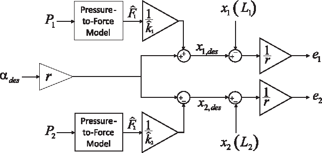
The desired actuator contractions
A separate PID controller for each actuator regulated the position errors ei by commanding desired actuator forces

For the revolute joint, two separate PID controllers commanded a desired force
By inverting Eq. (5), the desired forces
The performance of the Smart Braid feedback was compared to feedback from a rotary encoder on the joint. When using the encoder for feedback, the actuator-specific error value was simply the difference between the desired angle
This error was used in both PID controllers of Eq. (8). No compliance compensation had to be performed.
Experimental implementation, revolute joint
A Texas Instruments “inductance-to-digital converter” (TI LDC1612/4) 53 provided rapid measurements of the sensor inductance. This chip operates by exciting the natural frequency of a resonant tank circuit formed by an inductor and a capacitor in parallel. The Smart Braid sensors were connected in parallel with 390 pF capacitors. The series resistance of the Smart Braid sensors was ∼0.3 ohms. The inductance values from the sensors had a target sampling rate of 1 kHz. An analysis of the inductance measurements from the Smart Braids in relaxed conditions showed a root-mean-square (RMS) noise level of 0.24 nH.
In the revolute joint test fixture, a digital incremental encoder (Koyo Electronics Industries; TRDA-2E2500VD) provided joint angle measurements with a quadrature resolution of 0.036°. The pulley radius r where the cables were connected to the revolute joint was 25.4 mm. A force transducer (Omega LC201-100) was attached serially to the steel cable of actuator 2. This was used to characterize the force–pressure relationship of the actuators, characterize the stiffness of the actuator connections, and measure preload tracking performance. The systems were controlled with custom scripts in LabVIEW. The measurements from the test apparatus were collected and processed with a data acquisition unit (NI PXIe-6341), which used a PXI express chassis (NI PXIe-1073) to communicate with LabVIEW. Inductance measurements were collected using an I2C bus (NI USB-8451). The mass flow rate into the actuator lines was controlled with proportional pneumatic valves (Enfield LS-V05 s). The pressure in each actuator line was measured with pressure transducers (WIKA A-10) with a [0.41]MPa range and controlled with a custom controller with compensation for the nonlinear aperture flow across the valves.
54
A 250 Hz LabVIEW loop acquired data from the pressure sensors and sent commands to the valves. The system pressure was limited to 0.31 MPa. Estimates of
The two types of feedback were tested in random sequence at each of seven preload levels
Each controller configuration was tested on a fixed sequence of step changes for the desired joint angle
To evaluate the effectiveness of the compliance compensation in Eq. (6), the controller tests were repeated with the two load configurations that generated a nonzero net-torque (Fig. 3b, c). The unmodeled load torque renders open-loop control infeasible and stretches the actuator connections asymmetrically.
Results, revolute joint
Feedback control based entirely on soft, Smart Braid sensing is feasible. The Smart Braid feedback controller was able to track step changes in the commanded angle (Fig. 7). With no load torque, Smart Braid feedback led to an average RMS in the joint angle error of 1.73° (standard deviation [SD] 0.69°) during the last 5 s of each commanded angle (considered steady state, Fig. 8). The average RMS of the tracking error in the first 5 s of the commanded angles was 7.85° (SD 5.21°). Even with load torques of 0.65 Nm, the average steady-state error remained less than 2° (SD < 1°, Fig. 9).

Comparison of the effect of feedback type on the reference tracking of the revolute joint controller. On average, the encoder feedback (red lines) resulted in better joint angle tracking than the Smart Braid feedback (blue lines). During the first 5 s after the commanded step change, the average RMS of the error was 16% smaller in the encoder feedback case. In the last 5 s, the RMS of the encoder feedback error was, on average, 51% smaller than the Smart Braid error. In the case shown in this study, the desired preload was 10 N and no load torque was applied. Reported values were measured with the rotary encoder. RMS, root mean square. Color images available online at www.liebertpub.com/soro

Comparison of the steady-state error of the two feedback types used on the revolute joint under different preload conditions. Shown are the average RMS values across the three trials with no load torque. The vertical axis corresponds to the RMS of the reference error during the last 5 s of a commanded angle. The feedback from the encoder resulted in smaller errors in the steady-state tracking. Color images available online at www.liebertpub.com/soro
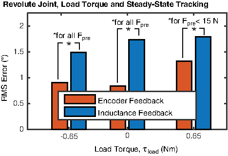
Comparison of the steady-state error of the two feedback types used on the revolute joint under different load torque conditions. The height of the bars represents the averages of the RMS error across all the commanded preload levels during the last 5 s of each of each commanded angle. The average error with encoder feedback was always less than with inductance feedback. This difference was statistically significant (p < .05) in all cases except when
The positional accuracy of the inductance feedback controller was comparable to the performance of a controller with feedback from the rotary encoder. During the first 5 s after a step change in the reference angle, the average RMS of the tracking error with encoder feedback was 6.60° (16% lower than with Smart Braid feedback, SD 4.56°, Fig. 7). Encoder feedback resulted in steady-state (during the last 5 s) errors with average RMS values between 0.8° and 1.3° depending on the load torque (SD < 0.8°, Fig. 9). This was smaller than the 1.5°–1.8° average RMS errors exhibited with Smart Braid feedback.
Figure 10 shows the measured preloads averaged over the last 5 s of each reference angle in the controlled trials (no load torque). With Smart Braid feedback, preloads of nearly 70 N were observed in the 12 N and 20 N conditions. The large preloads resulted from integral windup in the physically antagonized, yet independent, PID controllers.
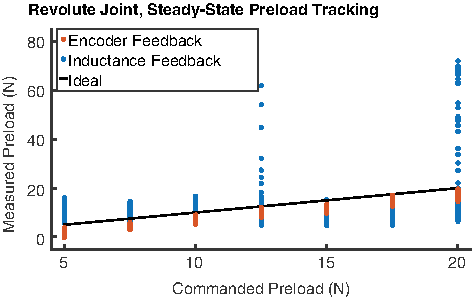
Shown are the preloads on the revolute joint averaged over during the last 5 s of each commanded angle in the controlled trials. The two types of feedback resulted in different preloads. The effectual single integrator of the encoder feedback resulted in better preload tracking than the two integrators of the inductance feedback. For the conditions shown in this study, no load torque was applied. Color images available online at www.liebertpub.com/soro
Continuum Manipulator
As a second example, we investigated the use of Smart Braid feedback in a simple, planar, one degree of freedom manipulator driven by Smart Braid McKibben muscles (Fig. 11). The manipulator consisted of two contracting McKibben muscles connected along their length to a bendable “spine.” Differences in actuator pressure values caused different levels of contraction in the actuators, creating bending motions in the structure. By measuring the lengths of the actuators by Smart Braid inductance measurements, the degree of bending was estimated. This estimate was used as feedback to control the tip angle of the manipulator. This Smart Braid feedback control was compared to open-loop control based solely on actuator pressure.
The continuum manipulator. Two Smart Braid actuators were attached to a thin, flat flexible beam. Contracting the actuators caused the beam to bend.
Estimation of continuum manipulator tip angle with Smart Braids
The continuum manipulator was modeled as having a constant curvature enclosing an angle
where Di is the diameter of the actuator cross-section. We assumed that the actuator radius was approximately the distance to the actuator centerline from the centerline of the thin beam.
McKibben muscles increase in diameter D as they contract. By approximating the shape of the McKibben muscle as a cylinder, the diameter D and centerline length l of the actuator were written in terms of the braid angle
These expressions were substituted for actuator 1 in Eq. (10) to relate the angle of the manipulator
The inductance of the Smart Braid sensors was approximated by considering the circuit formed by the wires to be a long solenoid.
39
The solenoid has a fixed number of turns N and a core with magnetic permeability
The number of turns in the solenoid circuit (
This approximation is appropriate even when the actuator is bent along its length. In this case, the circuit shape can be considered a segment of a toroidal inductor. The equation for the inductance of a toroid is identical to that of a straight long solenoid with a length equal to the circumference of the toroid centerline.
Equation (11) was used to express the inductance predicted by Eq. (13) in terms of the braid angle
Inverting Eq. (12) results in the following expression for the braid angle on actuator 1
Note that the following expressions are true:
Substituting Eq. (15) into Eq. (14) with the identities in Eq. (16) results in the following:
Equation (17) is defined for the inductance of the sensor on actuator 1. The inductance L2 of the sensor on actuator 2 is given by evaluating Eq. (17) with
In the range we are interested in, Eq. (17) can be approximated as a quadratic function. We numerically evaluated Eq. (17) from −90°
In the difference of L1 and L2, the quadratic terms are canceled and the linear terms are doubled
In practice, the inductance response of the two Smart Braid actuators will not be identical (Fig. 12). Due to the manual fabrication process, the sensors and their connection to the flexible spine will be different. They may differ in the arc length s they enclose, the effective length b, or the number n of turns in their helices. These anticipated differences lead us to assume that the inductance response of two actuators will be best approximated by different quadratic functions:
Still, the quadratic terms can be canceled
This leaves a form of
Calibration, continuum manipulator
The control variable for the continuum manipulator was the pressure difference
The value of baseline pressure
To calibrate the continuum manipulator,
The identified coefficients of Eq. (25) are listed in Table 4. The nonzero value of
The calibration data were also used to identify a relationship between the continuum angle and the measured inductance of the Smart Braid actuators (Fig. 12). A two-variable linear regression was used to identify the coefficients of Eq. (23). They are listed in Table 5. The RMS of the residual error was

Shown are the inductance values of the two actuators against the corresponding tip angle of the continuum manipulator. Inductance measurements are roughly quadratic with respect to the tip angle

Shown are the estimated values of the tip angle (
Feedback control of continuum manipulator
The Smart Braid feedback controller used inductance values and Eq. (23) to estimate the manipulator tip angle
This error e was scaled by the gain kc to calculate a desired angular rate
The desired angular rate was again scaled by the inverse of
The desired rate of pressure difference change
For comparison, an open-loop, feedforward controller was implemented that used the inverse of Eq. (25) to generate pressure commands for the actuators (Fig. 14b).

We compared the performance of two controllers on the continuum manipulator:
Experimental implementation, continuum manipulator
The continuum manipulator used the same data acquisition and pneumatic control hardware as the revolute joint. The manipulator was fabricated by fastening the outer, conductive braids of the actuators to a flexible spine. The spine consisted of two (0.83 mm thick) strips of Delrin plastic. To establish a ground truth, the angle
The value of the gain kc used in the inductance feedback loop was 5
Results, continuum manipulator
The inductance feedback controller was able to track the reference signal with a smaller steady-state error than the pressure feedforward controller. Visually tracked tip angle trajectories from typical controller trials are shown in Figure 15. The steady-state RMS error of the inductance feedback controller had an average value of

Shown are the tip angles of the continuum manipulator as recorded by the camera during two trials. The inductance feedback controller allowed the continuum manipulator to track the reference input with an RMS of
Discussion and Conclusions
In this work, we have shown how Smart Braid sensors can be used as feedback for the motion control of soft robotic systems. Smart Braids can provide rapid and precise measurements of actuator length. Motion control was demonstrated in both a revolute system and a bending continuum manipulator. For the revolute joint, we developed techniques to compensate for compliance between actuators and points of motion output. These techniques extend to other actuator length-sensing technologies.
The revolute joint was designed to rigorously compare the Smart Braid feedback to feedback from a rotary encoder. The high-inertia, lightly damped (
When load torques were applied to the revolute joint, the compliance compensation allowed the Smart Braid feedback controller to remain accurate. The addition of an external torque had only a small effect on the performance of the inductance feedback controller. Without the compliance compensation (and given the connection stiffnesses characterized in Table 1), a negative load torque would have led to ∼3° of steady-state error. The less stiff tendon of actuator 2 would have resulted in a 6° error with the positive load torque. With the compliance compensation, the average RMS of the steady-state error in each case was less than 2°.
Controlling the actuators individually with the proposed compliance compensation technique sometimes created large tensions in the system. The large preloads could be precluded by controlling the two actuators together with a single controller (as was effectually the case with the encoder feedback).
We also demonstrated Smart Braid feedback on the angle control of a bending continuum manipulator. The feedback used in this work permitted the manipulator to reach desired joint angles using only the inductance measurements from the Smart Braids. The closed-loop control of the manipulator resulted in more accurate reference angle tracking than the simple, open-loop control of pressure. The comparatively poor performance of the open-loop control was due, in part, to hysteresis and unavoidable friction in the system (Fig. 16).

Shown are tip angles and pressure values observed during the calibration and controlled trials. They exhibited hysteresis and nonlinearity. The black dots are the calibration data. The hysteresis is the main obstacle when inverting the calibration curve for open-loop feedforward control. In this article, the inversion was performed on a linear fit to the entire data set (dashed black line shown above). The colored dots are the data from the angle-control trials. In the controlled trials, the ambiguous relationship between the differential pressure and the tip angle is apparent. Color images available online at www.liebertpub.com/soro
The bend sensing of the continuum manipulator relied on only two sensors. It was limited to approximating the shape of the manipulator as a single segment with constant curvature. This approximation is not necessarily accurate in the presence of external forces and constraints. The constant curvature assumption is most accurate when applied to short segments of the curve. 56 Using Smart Braid sensors on multiple, shorter segments of the actuators could allow more accurate estimation of the end tip position and orientation. Similarly, the principles in this work could be extended to 3D manipulators.
The Smart Braid actuators in this work are slightly different than those used in our previous work. In our prior work, the wires of the Smart Braid sensor served the role of both sensor and reinforcing fiber.39,40 In our pilot work for this study, we found that the wires bearing the stress of the internal pressure would often yield under high and repeated strain. For this reason, we decided to use Smart Braid sensors on top of a plastic braid that would bear the stress. After 40 h of testing, the sensors showed no signs of wear. The addition of the Smart Braid sensor on top of the inner braid results in disparate length/diameter relationships in the wire braid and the plastic braid. In the revolute joint, this caused the Smart Braid sensor to have a larger diameter than the inner braid in contracted conditions (Fig. 2). In some applications, this would allow relative motion between the two braids, possibly biasing the estimates of the actuator length. A more sophisticated fabrication method could use a single layer of high-strength fibers with long flex life conductors.
Although the fabrication method of the actuators was different, the sensors were fabricated in the same manner as our previous work.
39
As such, they exhibited a similar sensitivity to the actuator contraction compared to sensors in our previous work. The actuators in our previous work showed contraction sensitivities of 6.8
Our results demonstrate that Smart Braids can control the motion of soft robotic systems. The Smart Braid sensors in this work enabled the closed-loop angle control of a revolute joint and a continuum manipulator using local, flexible sensors. It is only through closed-loop control that soft systems can become true autonomous agents, sensing and reacting to their own, changing environment.
Footnotes
Acknowledgments
Funding for this project was provided by NIH (GRANT: 1-R01-EB019834-2014 Wearable eMbots to Induce Recovery of Function). This material is based upon work supported by the National Science Foundation Graduate Research Fellowship under Grant No. DGE 1256260. Any opinion, findings, and conclusions or recommendations expressed in this material are those of the authors(s) and do not necessarily reflect the views of the National Science Foundation.
Author Disclosure Statement
No competing financial interests exist for Khai Yi Chin. Authors C. David Remy and Wyatt Felt are listed as inventors in a relevant patent owned by the University of Michigan (US Patent Application No. 14/743,062). Accordingly, future licenses could lead to revenue distribution according to the policies of the University of Michigan.
References
Supplementary Material
Please find the following supplemental material available below.
For Open Access articles published under a Creative Commons License, all supplemental material carries the same license as the article it is associated with.
For non-Open Access articles published, all supplemental material carries a non-exclusive license, and permission requests for re-use of supplemental material or any part of supplemental material shall be sent directly to the copyright owner as specified in the copyright notice associated with the article.