
Abstract
Abstract
Current commercial wearable gait exoskeletons contain joints with stiff actuators that cannot adapt to unpredictable environments. These actuators consume a significant amount of energy, and their stiffness may not be appropriate for safe human–machine interactions. Adjustable compliant actuators are being designed and implemented because of their ability to minimize large forces due to shocks, to safely interact with the user, and to store and release energy in passive elastic elements. Introduction of such compliant actuation in gait exoskeletons, however, has been limited by the larger power-to-weight and volume ratio requirement. This article presents a preliminary assessment of the first compliant exoskeleton for children. Compliant actuation systems developed by our research group were integrated into the ATLAS exoskeleton prototype. The resulting device is a compliant exoskeleton, the ATLAS-C prototype. The exoskeleton is coupled with a special standing frame to provide balance while allowing a semi-natural gait. Experiments show that when comparing the behavior of the joints under different stiffness conditions, the inherent compliance of the implemented actuators showed natural adaptability during the gait cycle and in regions of shock absorption. Torque tracking of the joint is achieved, identifying the areas of loading response. The implementation of a state machine in the control of knee motion allowed reutilization of the stored energy during deflection at the end of the support phase to partially propel the leg and achieve a more natural and free swing.
Introduction
T
Many studies suggest that one reason why biological systems can successfully interact with the environment is that they have the ability to modulate joint impedance, 9 understanding mechanical impedance as the additional force created at the output by load motion. The implementation of a joint impedance control approach requires the actuator to be a high-precision force source. 10 Complete, active control of the joint impedance in active orthosis applications suffers from certain drawbacks. Most implementations of impedance control techniques using force feedback with traditional stiffness joints require a significant level of computation and require constant energy drain, as the motor must apply a constant force despite the fact that no work is being performed. Current commercial devices for gait assistance and rehabilitation present joints actuated with stiff actuators, which result in devices that feature poor adaptability to unpredictable environments, consume more energy, and are not appropriate for human-machine interactions.
These mechanisms primarily lack compliant properties that are associated with safer human-machine interactions and semi-natural actuation. Robot philosophy has gradually changed into something that is more human oriented. Robots of the present and future are no longer supposed to be solid, isolated, or rigid but rather adaptive, cooperative, and compliant entities in our daily lives. 11 Compliance is a must have in robotic exoskeletons because of its ability to minimize large forces due to shocks, safely interact with the user, and store and release energy in passive elastic elements. In addition, by adjusting the natural dynamics of a mechanical system, it will have a natural motion close to the desired motion, which could translate into reduced energy consumption.
This article presents the preliminary assessment of a compliant exoskeleton. The ATLAS-C Lower Limb Exoskeleton contains compliant joints that are specifically developed for this robotic device. The proposed actuators integrate in their mechanism a force sensor that allows force feedback at the joint, taking advantage of the elastic elements that simultaneously regulate the joint impedance. The mass and inertia of the actuators are minimized by the compact design and the simultaneous use of each component for more than one utility (i.e., sensing and acting). 12
Adding compliance to the actuators can absorb significant position errors, thus avoiding damage to the system itself and, of course, ensuring patient safety. Since elastic elements can store energy during foot support, this stored energy can be used later for power generation.
The outline of this article is as follows: We begin with a brief overview of the joint biomechanics; this preliminary section intends to identify and highlight the requirements to be fulfilled by the compliant joints to be implemented in the robotic exoskeleton. The section dedicated to materials and methods presents a short description of the ATLAS lower limb exoskeleton, followed by the proposed compliant leg model to be implemented into the exoskeleton prototype. A description of the chosen actuators will be given, and the compliant exoskeleton along with the experimental setup will be introduced. The section for results and discussion of the preliminary experimental assessment of the compliant exoskeleton will be presented before the general conclusions and future work.
Joint Biomechanics
Humans are capable of autonomously producing a wide range of stable movements in environments with unpredictable disturbances. Dynamic control of joint stiffness is crucial for humans to adapt to changes in environmental conditions. 13 Muscles in biological systems modulate the stiffness and position of the joint, achieving high adaptability, force transmission, and significant reduction of energy expenditure. 9
Muscle-tendon units (MTUs) are responsible for the human ability to excel against the best robots during physical interaction with the world, especially interaction that involves impacts or kinetic energy transfers. 14 The high power/weight ratio, force/weight ratio, compliance, and control of muscle when compared with traditional robotic actuators are the main barriers for the development of machines that can match the motion, safety, and energy efficiency of the performance of a human being or an animal.
Focusing on the design of powered exoskeletons and based on the data collected by the clinical gait studies 15 in combination with an understanding of the MTU, the different behaviors that each joint should fulfill are analyzed. Figure 1 presents the relationship between torque and joint position along the locomotion cycle, where the dashed circle indicates the beginning of the cycle with the heel strike. This relationship can be seen as the impedance of the joint, or the proper stiffness needed to achieve a safe and energy efficient human-like gait. The joint requirements are discussed next.

Joint torque versus angular position along the locomotion cycle.
Hip
From the joint trajectory, it can be appreciated that the hip presents a semi-sine pattern. This cyclic movement could benefit from elastic elements connected in series to the joint to reduce power peaks. 16 The range of motion (RoM) of the hip joint in the gait cycle is from approximately −20° to 40°. There are positive values and negative values in the joint torque associated with power generation, which indicates the need for a bi-directional actuator. Negative extension torque is required in the early stage, as the hip supports the load on the leg. Hip torque is positive in the late stage and early swing, as the hip propels the leg forward during the swing. In the late swing, the torque becomes negative as the hip decelerates the leg before the heel-strike. 17 The average power is positive. The hip joint plays an important role in human walking.
Figure 1a presents the relationship between torque and angle for the hip joint during the locomotion cycle; this relationship is related to the impedance of the joint in the gait, sometimes also discussed as joint stiffness. Two marked vertical lines can be noticed, indicating the generation and absorption of power. High torque is generated in both directions along the gait cycle. The hip is the primary joint that makes walking possible. Based on the antagonistic behavior of natural muscle, for this joint, two MTUs implemented as bidirectional actuators in series with an elastic component attached to the hip could achieve bidirectional motion.
Knee
Along the gait cycle, the knee experiments show several variations from power generation to power absorption. The knee is a multifunctional joint with an RoM of ∼0° to 60°, presenting different functionalities during the locomotion cycle. These features make complicated and energetically expensive to replicate the natural motion at the knee with traditional actuators. The human muscle is capable of adapting and absorbing energy without the need for dissipating it; instead, this energy can be stored or transferred to other joints. 18
During the support phase, the knee absorbs a certain amount of energy during flexion and generates as much as the same amount of energy for its extension; this load response occurs between 0% and ∼40% of the cycle of walking. When analyzing the variation of impedance at the knee along the locomotion cycle, it can be seen in Figure 1b that the load response behaves similarly to an elastic element acting and its corresponding return to equilibrium position following a typical hysteresis curve. In this section of the gait, the knee should behave as a spring with a constant K1 based on the weight acceptance and the ground itself. The loading response is followed by a knee flexion just before the toe-off during the pre-swing. The spring constant at this stage should be lower than that of the prior section, indicating the ability to tune the elastic properties. The energy absorbed during the pre-swing could be used by another joint or stored for a later stage of the gait.
The beginning of the swing requires the knee to complete the flexion to assist the ground clearance. The power required from the knee to achieve the flexion is low, as only the inertia of the foot and shank needs to be moved, and in dynamic and fast walks, the kinetic energy of the locomotion can assist this flexion. An active element needs to be connected to the knee to supply the required power and hold the position as long as it is needed. At slower gaits, this actuation has more relevance, because there is no kinetic energy contributing; instead, the weight of the limb opposes the flexion.
During the end of the swing phase, the leg transitions from a flexed knee to a fully extended knee before the heel-strike. This knee motion is achieved by utilizing the hip movement and leg inertia. By reducing the impedance at the knee to a minimum, the kinetic and potential energy can be used to extend the knee without generating significant power at the joint. The energy stored at the pre-swing can also be used to successfully achieve extension, as is done in many prosthetic devices.
Ankle
The ankle joint during the gait cycle produces positive and negative power; at normal walking speed, it can be appreciated as a significant positive power at the push-off as can be seen in Figure 1c. This power generation occurs in a very small instant, similar to an impulsive force, and represents the main complication when designing ankle joints for exoskeletons and prosthetic devices. The RoM of the ankle is ∼30°, from approximately −15° to 15°, and during the support phase during a dynamic walk, it can store part of the energy required during the push-off by adapting to the ground and the weight of the subject.
During the support phase, at the loading response, the ankle behaves as an elastic element. Two elastic constants can be identified. This adjustment in the impedance is related to the adaptation of the foot to the ground and the load due to the subject's weight. The energy to achieve this negative power can be stored at the tendons, and this energy is released at the push-off in combination with an active actuation. This power supplied at the joint occurs in a very short time window, which makes emulating this behavior with a traditional electric motor a complicated task in powered exoskeletons.
Materials and Methods
In this section, we present the first ATLAS exoskeleton prototype actuated by stiff joints. The leg model designed to provide compliance to the robotic exoskeleton is discussed along with the two compliant systems that are specially designed to be implemented in the joints of the exoskeleton. Finally, the developed compliant exoskeleton is presented and the experimental setup is described.
The first ATLAS prototype: A stiff actuated system
The ATLAS exoskeleton was conceived for children's gait assistance, and it can be considered an active Trunk-Hip-Knee-Ankle-Foot Orthosis (THKAFO). ATLAS is intended to support users of up to ∼40 kg in weight and from 130 to 165 cm in height. The exoskeleton device allows the wearer to walk at low speed over a flat regular surface. It has 6 actuated degrees of freedom (DOF), with 3 DOF per leg; hip, knee, and ankle provide movement in the sagittal plane.6,19 The ATLAS prototype contains six stiff actuators to provide the required power during locomotion to the six sagittal joints. The device presents a lightweight mechanical structure of ∼10 kg, including actuators. The user's body is attached to the structure through comfortable belts at the shank, thigh, and torso. The flexion and extension motion of the hip, knee, and ankle joints are driven by electrical brushless Maxon motors in combination with harmonic drive units. The setup can provide repeatable peak torques up to 76 Nm, and average torques of 32 Nm at more than 20 rpm.
The implemented motor-gearbox complex provides a large power-to-weight ratio while keeping flat enough not to affect the user's motion. However, this large ratio results in very stiff joints, which are not desired when interacting with humans and in the presence of constant impacts, such as those experienced during heel-strike, and changes of directions of the links.
The ability of torque control, adaptability, and providing a safe human-machine interaction are the main goals when developing fully functional active exoskeletons for paralyzed individuals, such as quadriplegics and those with muscular dystrophy, especially when children are the intended users, as in the case of ATLAS exoskeleton. The target users of the device bring the added difficulty of stability control, as many of these subjects are not able to achieve torso control or provide postural stability by means of crutches or common walkers, as in many of the commercial devices available for adults.
Walker-balance
During the development of the ATLAS project, balance issues due to the subject's lack of strength or mobility in the arms were approached by developing a special walker capable of attaching itself to the exoskeleton, avoiding the use of crutches or conventional walkers. The device was designed to provide stability in the lateral and frontal planes, and a detailed description can be obtained from the patent documents ES 2 459 866 B1, EP2907495, and US2015265490. The walker was equipped with a mechanism allowing the user to sit and stand while dressed with the exoskeleton. Another mechanism embedded in the walker provided the freedom of vertical excursion at the point of attachment of exoskeleton and walker, which keeps the lateral and frontal planes constrained. The vertical displacement allowed the natural motion of the Center of Mass (CoM) of the subject during the locomotion cycle. Figure 2 presents a CAD representation of a simplified walker frame comprising the mechanism that allowed the required up and down motion in the sagittal plane.

Walker frame for balance and center of mass vertical motion.
The simplified realization of the walker device was implemented to perform evaluations of the exoskeleton when walking in a straight line in the laboratory. The slider connected to the main frame and is attached to the back support of the exoskeleton, constraining motion in the lateral and frontal planes, as previously stated. A vertical displacement of ∼5 cm, which is associated with the CoM displacement during the gait, is allowed.
Compliant leg model for atlas
To provide the desired compliance properties to the ATLAS exoskeleton, based on the biomechanical analysis conducted in analysis of the joints biomechanics and focusing on the sagittal joints of the robotic device, a model of the leg combining hip-knee-ankle is presented in Figure 3. The hip joint is characterized by the cyclic generation of positive and negative power. The knee and ankle joints present a wider range of actuation, with several regions of energy absorption that can be reutilized for power generation in different phases of the gait.

Compliant leg model.
Two actuation systems have been designed and developed in our group to be implemented into the exoskeleton's joints. Adjustable Rigidity with Embedded Sensor (ARES), 20 and its improved version, ARES-XL, are adjustable compliant actuators with torque measuring capabilities. Both systems present similar characteristics in terms of their main components, component arrangement, torque tracking capabilities, and size. However, there are particular properties that make them more suitable to be implemented into the compliant exoskeleton, based on the proposed leg model.
ARES actuator for the hip joint
An ARES actuator, presented in a previous work, 20 can provide the desired properties to the hip joint.
ARES is a variable stiffness actuator that can be classified as part of the group with a controllable transmission ratio. 21 Its structure is arranged along the device's links, which is intended to reduce the protrusion from the laterals of the exoskeleton. The stiff set coupled with the compliant mechanism provides the adaptability to the actuator as well as the means for sensing the torque exerted at the joint.
ARES actuation presents a simpler mechanism compared with ARES-XL whereas providing torque measurement and compliant behavior, making the first system the preferred option to implement at this highly actuated joint. However, from joint biomechanics' analysis, where cyclic behavior at the hip joint is observed, no significant stiffness modulation occurs during the gait. For this reason, a simplification of the ARES actuator is introduced.
ARES simplified for the hip joint
By replacing the slider element with a fixed element attached at a manually adjustable distance from the joint axis and reducing the size of the slotted bar—S1B1, an actuator with intrinsic compliance is obtained (Fig. 4). This simplification of the ARES mechanism is essentially a conformal rotary actuator with series elasticity. The main working principle of ARES and its torque measuring capabilities are maintained.

ARES simplification, an SEA rotary actuator for the hip.
The associated relationship used to calculate the torque at the joint is the same used for ARES, keeping Lo as a constant value. The Implemented springs provide an equivalent constant of 88 Nm/mm, and the constant distance Lo for this particular realization will be 70.5 mm.
where Lo is the distance from the axis of rotation of the joint to the pivot—S1P1, K is the elastic constant of the springs, γ is the joint deflection, and ΔX is the elastic elements compression.
ARES-XL actuator for knee and ankle joints
ARES-XL is an improved version of ARES. This novel actuator is capable of providing the same characteristics achieved with ARES while outperforming the range of stiffness and deflection allowed by the joint. A special locking mechanism (add-on) can be implemented in ARES-XL to lock a certain joint deflection or store the elastic energy for later uses according to the joint requirements. Figure 5 presents a CAD view of ARES-XL. The main components of this compliant actuator are shown, where the coupling between the main actuator and the compliant structure is achieved by means of a double bar linkage. The distance L2 can be adjusted by means of a second motor, similar to ARES. By knowing the spring compression, along with the distance L2 and system geometry, torque measurements can be calculated when a load is exerted at the joint.

ARES-XL system. Principle components and geometry. ARES, Adjustable Rigidity with Embedded Sensor.
ARES-XL with locking for the knee joint
The knee is a versatile joint, with higher torque generation in the extension direction than in the flexion, during the gait cycle. This joint acts as a compliant passive joint during several segments of the locomotion cycle. Based on joint biomechanics and Figure 1b, the presence of different stiffness levels is evident. The implementation of a system that is capable of adjusting its stiffness during the walking cycle is desired at the knee.
ARES-XL with a locking mechanism is chosen due to its large deflection and low achievable stiffness and the possibility of implementing a locking mechanism to store energy and/or locking deflection to be later released. Large compliant capabilities can be exploited during the loading response of the knee. Later in the gait cycle, the flexion of the knee at the beginning of the swing can occur while maintaining the deflection during pre-swing, as well as storing energy, by engaging the locking mechanism. Finally, allowing a partial natural swing at the end of the gait cycle, achieving zero stiffness in the proper moment of the gait for extending the knee uses the potential energy and the previously stored energy at the pre-swing.
An additional elastic element can be implemented in the compliant mechanism to increase the resistance in the extension direction. Thus, the spring force used to calculate the exerted torque in the ARES-XL will correspond to a piece-wise force where the regular spring constant will be 16.8 N/mm. The added springs will only act after a certain compression is achieved given the following relationship for the extra spring constant:
The resulting relationship for the torque calculation is given by
where
α and
ARES-XL without locking for the ankle joint
Typically implemented as a passive joint in several exoskeletons, the ankle is characterized by adapting to the reaction of the ground and the user weight. The dorsiflexion motion during the support phase corresponds to the reaction of the joint behaving as a compliant passive system. In a dynamic gait, during the toe-off, the push up occurs. This motion produces a sudden change of direction in the joint with a power profile similar to an impulsive force applied to the foot. The energy required during this phase can be provided, in part, by the energy stored at the support phase and a main actuation system. The main difficulty is associated with the acceleration required by this impulsive power, which is typically not achievable with the electric motor-gearbox combinations. ARES-XL should be capable of allowing a large deflection during the support phase, followed by a sudden increase in stiffness in the compliant mechanism just before the toe-off. A high impulse can be delivered to the joint, leaving the main actuator with less power to deliver. ARES-XL, without need of a locking mechanism, will be implemented at this joint because of its larger deflection-energy storing capability. Similar to the plain ARES-XL with identical springs of 16.8 N/mm constant, the torque relationship is given by
ATLAS-C exoskeleton: compliant joints
The ATLAS exoskeleton was equipped with compliant joints in its left limb while maintaining the traditional stiff actuators in the right limb. Figure 6 presents the compliant joints implemented in the exoskeleton prototype and a CAD view highlighting the systems in use. At the hip, the simplified version of ARES will provide compliance and torque measuring properties, maintaining a reduced size. Two versions of the ARES-XL are implemented at the lower joints, one at the knee including the add-on locking mechanism and the plain version of the ARES-XL at the ankle. The exoskeleton will be evaluated by programing a locomotion cycle under different conditions to analyze the data collected from the different feedback sensors.

ATLAS-C, a compliant exoskeleton.
Experimental setup
The assessment of the compliant exoskeleton performance was made with the assistance of the simplified walker frame for balance. The back of the exoskeleton was connected to the slider in the walker, allowing the required mobility for the CoM displacement. To emulate the subject in the exoskeleton, a test dummy was used. The target subjects for these robotic devices are sensitive subjects that cannot be exposed to the preliminary evaluations performed in this experiment. However, the use of a test dummy with matching mass and inertial properties as a child of 10 years old is a suitable option to conduct the experiment. The test dummy presents a socket joint at the hip, hinges at knee and ankle, and flexible feet. Similar to the target users, the dummy is not capable of providing balance to the system; thus, the combination of exoskeleton, walker, and gait control is required to achieve a forward human-like gait.
Control
The exoskeleton is equipped with an MyRIO on-board controller from National Instruments. This hardware presents a reduced size and various inputs/outputs that allow control and constant communication with the exoskeleton devices. The MyRIO can communicate with the main PC via wireless communication to transfer the logged data from the exoskeleton components. Compliant joints are implemented in the left limb, whereas stiff actuators provide power to the right limb. Maxon ESCON 50/5 motor drivers are used to command the motion to the main motors—M1, whereas Maxon EPOS 24/5 U are used to control the position of the slider elements in the compliant mechanism by means of—M2. Each exoskeleton joint is equipped with AS5045 magnetic encoders via serial peripheral interface bus communication and are used to feedback the actual joint positions.
From the exoskeleton hardware and instruments, position, set points, stiffness level, and current consumption are continuously collected and logged during experiments for later analysis.
Trajectory
A predefined trajectory was commanded to the exoskeleton to evaluate the behavior of the compliant joints during the gait cycle. The robotic exoskeleton is actuated only in the sagittal plane, and as a consequence, some considerations need to be taken into account during the locomotion cycle.
The walker constrains the lateral and frontal motion because the abduction required for weight shifting during the gait cannot be provided. This motion would not be possible when experimenting with a test dummy or the intended subjects, as they are not capable of providing this motion by themselves. To address the issue, the knee flexion during swing needs to provide mostly all the ground clearance.
The gait commanded to the exoskeleton is at low speed and based on predefined trajectories of healthy subjects. To assist with the ground clearance and the sagittal stability, the leading leg will remain still while the hip of the swinging leg achieves its maximum forward position, and the end-swing begins. The commanded trajectory implemented and shown in Figure 7 aims for a natural-like gait, with an extended support phase to assist the ground clearance during the slow gait.

Joint trajectory; the highlighted area is where the leading leg remains still to assist ground clearance.
Experimental Results and Discussion
To assess the response of the exoskeleton to the compliant joints, two main experiments were performed. Torque tracking at the joints during locomotion followed the modified trajectory under different load conditions to evaluate the adaptability to the ground, dynamics, and trajectory deviation. Online stiffness adjustment at the knee is also analyzed and discussed.
Torque tracking during locomotion
Taking advantage of the embedded force sensor in the compliant actuators, the torques during the commanded walking cycles were calculated and the results were analyzed for discussion. The relationships (1), (3), and (4) are used to calculate the exerted torques at the joints.
The lower limb of the test dummy was used as a load in the exoskeleton. With an equivalent weight near to 20 kg and an articulated hip, knee, and ankle, the compliant exoskeleton was evaluated under different stiffness levels: medium, high, and fully stiff. By blocking the elastic elements in the compliant mechanism, a completely stiff configuration can be achieved for comparison purposes.
Three load conditions were tested:
• Follow trajectory in the air—exoskeleton alone (Air-No load). • Follow trajectory in the air—exoskeleton with lower limb of the test dummy strapped inside the structure (Air-Loaded). • Follow trajectory on the ground—exoskeleton with lower limb of the test dummy strapped inside the structure (Ground-Loaded).
Comparisons of the results obtained during the different load conditions are made. The angular positions and the torque calculated implementing a high level of stiffness in both ARES-XL actuators are shown and discussed next.
In Figure 8, it can be shown that the test dummy requires most of the torque exerted by the hip actuators. The behavior of the hip joint when the exoskeleton is walking on the ground presents small deviations from the trajectory as a response to the inertia of the body. It also has appreciably larger torque slopes during the ground experiments. The hip takes longer to change torque direction, and later, the body weight contributes to the torque generation when the body is in motion. This behavior shows the adaptable behavior of the compliant hip joint as a response to the body inertia and the commanded trajectory. The highlighted region indicates the section of the gait where the leading leg remains still. It can be noticed that the generation of extra torque to maintain the position is a consequence of the low walking speed, making it difficult to achieve a dynamic gait.

Torque tracking at the hip under different conditions of load.
The torques exerted at the knee are more affected by the ground reaction. The knee torque is directly related to the joint angular position only during the swing phase, but in the stance phase to maintain the knee extension, the reaction of the ground produces a significant increase in the torque when compared with the experiments in the air. This can be explained as a reaction of the joint to the acceptance of the body weight throughout the support phase. Figure 9 presents the joint positions, torques, and joint deflections during the three experimental conditions. Three sections are highlighted: The first area (S1) corresponds to the heel strike and the beginning of the loading response, followed by an extended loading response area (S2), up to before the pre-swing, and a final section (S3) highlighting the pre-swing phase. During the swing, the torque changes direction, as does the joint deflection. However, the energy that could be gathered during this deflection before the swing (pre-swing) is wasted as soon as the leg loses contact with the ground and the torque changes direction. This deflection could translate into stored energy by implementing the add-on locking functionality or by incrementing the stiffness at the joint in the previous swing; thus, less deflection energy would be wasted.

Torque tracking at the knee under different load conditions.
The ankle joint torques and deflection profiles when the test dummy is placed on the exoskeleton present similar behaviors between the conditions evaluated, as seen in Figure 10. The torques required for flexion and dorsi-flexion are related to the inner foot resistance or stiffness at the dummy's joint, more than to the ground reaction. During the heel-strike, the first highlighted area shows the reaction of the joint. A small bump in the torque tracking plots indicates the foot adapting to the ground contact. This bump is followed by the dorsiflexion of the foot due to the body weight, which indicates the presence of the torque when ground contact is involved before the experience in the trial in air. This torque remains along the support phase (second highlighted area); however, at the push-off, the torque, instead of presenting a short increase before the foot leaves the ground, drops sharply to zero, continuing to change direction. This indicates the foot abandoning the ground before it is expected to, based on the analysis of clinical gait data. This particular behavior is attributed to the multiple constraints imposed to the gait in terms of degrees of freedom.
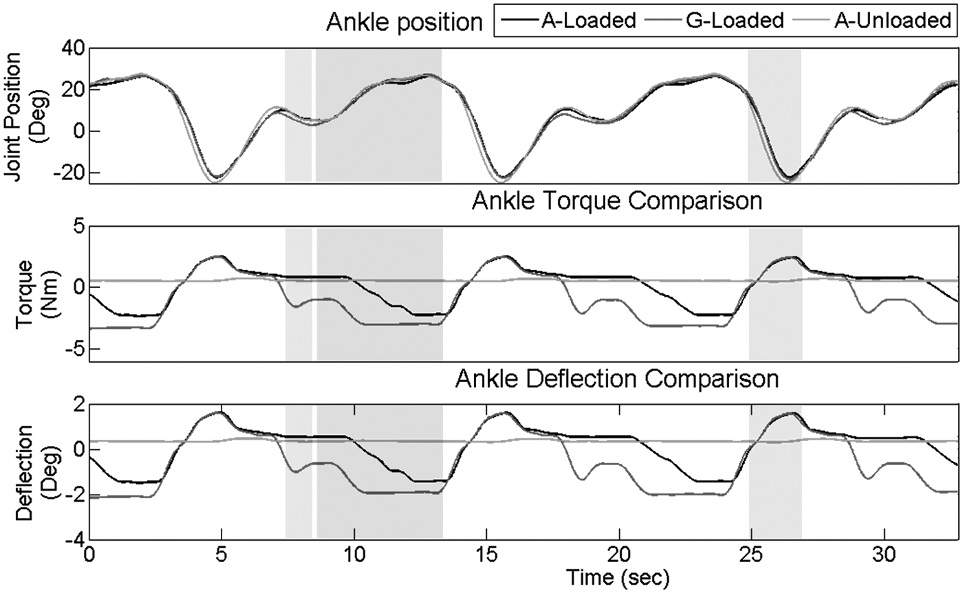
Torque tracking at the ankle under different conditions of load.
Stiffness adjustment at the knee during locomotion
To evaluate the response of the exoskeleton's joints when online adjustments of the stiffness are made, a set of state machines were implemented at the knee motion controller. The goal of these experiments is to assess the behavior of the joint during the main sub-phases of the gait: loading, pre-swing, and swing.
The knee joint is characterized by a versatile behavior. The joint adapts to the ground during the support phase, as a consequence of the reaction to the ground and the loading of the body. The torque tracking showed high torque during the loading response, and joint deflection at pre-swing. However, the potential energy generated in this deflection is wasted during the beginning of the swing, when the directionality of the torque changes, associated with changes in the joint deflection. To evaluate alternatives, to either reutilize such energy, or to avoid wasting the energy, two state machine controllers are proposed. The diagrams of such control strategies to implement at the knee are shown in Figure 11.

State machine commanded at the knee.
The first control strategy, named “Var-L1,” presented in Figure 11a intends to exploit the deflection energy at the pre-swing by means of the locking mechanism to be engaged at ∼10° of deflection in the extension orientation. Once the knee is completely flexed at swing, the lock can be disengaged, momentarily decreasing the stiffness of the system and achieving part of the swing by using potential and stored energy. The second control strategy, “Var-S1” (Fig. 11b), intends to minimize the wasted (not stored) energy at the pre-swing by increasing the stiffness of the joint at that sub-phase, reducing the deflection allowed to the joint during the loading response.
Figure 12 presents the knee joint positions and deflections resulting from both strategies during different experiments and a comparison with the system with a fixed compliance. During the loading response, both strategies allow deflection at the joint. A larger deflection occurs at the Var-L1 as a consequence of lower stiffness. During the holding position of the leading leg followed by the pre-swing in Var-L1, the stiffness of the joint is decreased to allow a larger deflection that can secure the engaging of the locking mechanism.

Knee results with state machines implemented.
It can be noticed that when the Var-S1 is implemented, a large deflection associated with the loading response is experienced at the knee. In the second highlighted area, the stiffness of the system is increased followed by a minimum deflection at the joint. When the foot leaves the ground at the beginning of the swing, the body weight is no longer exerting a load at the joint. The change of direction at the knee torque causes the elastic elements to act in the opposite direction. The previous deflection opposes the flexion at the knee, thus a low deflection at the pre-swing is desired when implementing this strategy. The Var-S1 strategy seeks to provide the joint with adaptability at the loading response and support phase and to adjust to stiffer configurations when compliance will not be useful. This control strategy can be implemented with ARES and ARES-XL, and a larger deflection at the loading response can be achieved with ARES-XL.
The stiffness level at the loading response when Var-L1 is implemented allowed some deflection for adaptation. In the holding position region, the stiffness is decreased to ensure a deflection greater than 10°, where the locking can be engaged. This locking position could be adjusted to larger degree values. It can be seen in Figure 12 that the deflection reached values of ∼20° in this particular experiment.
During the beginning of the swing, the deflection is constrained, as can be noticed in the second highlighted area, that at ∼10°, the value is locked. When the maximum knee flexion has been reached, the energy from the support phase is stored and can be re-utilized for providing extension without the action of the main motor—M1. At this point, the slider element is commanded to adjust L2 to a minimum value. The displacement of the element produces tension in the cable attached at the pawl—L1, causing the locking to be disengaged. The first highlighted region in Figure 12 shows the moment when the locking is disengaged. The deflection at the knee drops sharply, producing extension motion in the swinging leg. The potential energy and inertia from the shank, along with the stored deflection, allow the joint to move like a free swing. The joint position shows that the swing extension occurs faster when implementing the Var-L1 scheme. The main motor—M1 could use the impulse given by the free swing to continue the extension smoothly.
Figure 13 shows the velocity at the joint and the current consumed by the main motor—M1 during the tests. A significant increase in the velocity can be noticed during the swing. The increase in the velocity occurs without alterations in the current of the main motor, which is evidence of the increase in velocity being caused by the release of the deflection and the low stiffness commanded. The swing during locomotion should be achieved at a natural velocity given by the potential energy and the knee as a free joint. Constraining the velocity of the swing affects the balance when walking dynamically, and the implementation of this feature could be beneficial in terms of stability and naturalness of the gait.

Knee results with state machines implemented—velocity and current.
Increasing the walking speed to achieve a self-selected velocity from the user still requires further research in terms of safety and actuation power. Preliminary evaluation of implementing the Var-L1 strategy shows that great adaptability can be provided during the loading phase, with the ability to store the energy obtained at pre-swing to further exploit it at the end of the swing. ARES-XL appears to be an actuator that could deliver the required versatile functionality of the knee while actuating based on the interaction of the user with the ground and reutilizing the absorbed power during the locomotion cycle.
Conclusion
Walking is one of the most basic and common actions in life; however, it involves very complex mechanisms, including energy storing, transfer, and return, which depend on a highly complex anatomical bone, muscle and tendon structures. During the locomotion cycle, continuous interaction between the ground and the feet occurs. Natural adaptation of joints during normal walking is a requirement that must be met by lower-limb robotic exoskeletons.
The resulting system is intrinsically compliant, capable of measuring the torque exerted at the joint, and similar in weight and size to the stiff counterpart. During the walking assessment, absorption of shocks was evidenced in the elastic elements. The joint followed the predefined trajectory, allowing small deviations as a consequence of ground reaction and inertial forces. These are desired behaviors in the compliant exoskeleton that contribute to smaller forces being transmitted to the mechanical structure and adaptation properties.
Different stiffness configurations can produce more or less deflection at the joint at a given torque. The joint adaptability can vary for different subjects based on the load transferred to the exoskeleton's joints.
A considerable number of potential users of robotic exoskeletons suffer spasmodic movements and non-uniform joint rigidity; therefore, providing intrinsic compliance to their joints is absolutely necessary.
Based on the joint functionalities, when implementing the compliant actuators into the ATLAS exoskeleton, the hip joint could have been actuated by any of the designed actuators. However, to the authors' understanding, simply by providing compliance and torque measuring capabilities to this joint, its behavior should be appropriate. With that in mind, an adaptation of ARES was implemented, removing the compliant frame, and setting the system to a fixed stiffness given by a manually adjusting the distance, thus behaving as a series elastic actuator.
Two control strategies were tested at the knee of the exoskeleton. By implementing two state machine controllers, ARES-XL was evaluated with and without adding the locking mechanism. The results obtained with this configuration could also be achieved with ARES. The goal of the experiment was to validate that tuning the joint stiffness can allow adaptability during the loading response and larger adaptability/deflection could eventually translate to achieving the loading response passively. The joint behaves simply as a rotational spring. From the experiments, it is shown that during the loading response, large deflections can occur in the leading leg. At the middle of the support phase, the stiffness can gradually increase to reduce the deflection at the joint at pre-swing. Otherwise, any deflection would produce motion in the opposite direction when the foot leaves the ground. This energy is wasted and can affect the ground clearance, thus increasing the stiffness on the system, which significantly reduces the deflection at that phase. Deflections of 10° or more were experienced at the loading response, and by successfully adjusting the joint stiffness at the pre-swing, the wasted deflection at the swing is less than 3°.
The locking mechanism included in the ARES-XL actuator proved to be successfully engaged in the loading response, blocking the deflection at a given position. When the locking control strategy was implemented, the load exerted during the beginning of the swing to flex the knee did not affect the previous deflection, nor did it cause the pawl—L1 to disengage. When the extension of the knee is commanded at the end-swing, the disengaging of the lock, combined with adjusting the stiffness to a very low value, causes the knee to behave as a free pendulum that is partially extended at the knee without effort and a velocity given by the inertia of the body and its potential energy.
The stored deflection energy can be increased by adding teeth to the element in the main motor—M1, allowing different locking positions. From the experiment, at pre-swing, the body weight can produce deflections at the knee of up to 20°. This deflection could later translate to 20° of extension by means of potential energy released at the end of swing.
During the walking assessment, the ankle joint did not behave as expected. From the analysis of the data, it seems that several constraints used to achieve a natural walking-like gait affected the foot reaction with the ground and caused the foot to prematurely leave the ground.
This work presented a preliminary evaluation of a compliant exoskeleton. The general results show that as expected from the literature, intrinsic compliance in the exoskeleton's joints translate into adaptability to the environment. ARES-XL outperforms ARES in compliant capabilities, but to exploit them in the exoskeleton, the implemented controller needs to take the ground reactions into consideration.
Future work
The compliant exoskeleton will be evaluated with healthy subjects by tracking the joint torques during a predefined trajectory with high stiffness in order to identify the sections of loading response, pre-swing, push-off, and swing.
A control strategy with state machines at knee and ankle joints based on the results from healthy subject evaluations will be implemented, and the behavior of the exoskeleton as well as the power consumption will be analyzed and compared against stiff conditions.
The possible implementation of a servo motor to mechanically control the locking pawl—L1 will also be studied along with increasing the DOF in the walker frame to improve the human-like gait.
Footnotes
Acknowledgments
This work has been partially funded by the Spanish National Plan for Research, Development, and Innovation through grant DPI2013-40504-R and EU-FP7-ECHORD++ Experiment 401 EXOTrainer. Mr. Cestari would like to thank the Spanish Ministry of Economy and Competitiveness for funding his Ph.D. research.
Author Disclosure Statement
No competing financial interests exist.