
Abstract
Abstract
To perform untethered operations, soft robots require mesoscale power units (10–1000 W) with high energy densities. In this perspective, air-breathing combustion offers an interesting alternative to battery-powered systems, provided sufficient overall energy conversion efficiency can be reached. Implementing efficient air-breathing combustion in mesoscale soft robots is notoriously difficult, however, as it requires optimization of very small combustion actuators and simultaneous minimization of fluidic (e.g., hydraulic) losses, which are both inversely impacted by actuations speeds. To overcome such challenges, this article proposes and evaluates the potential of hydrogen-powered, hydraulic free-piston pump architecture. Experimental data, taken from two combustion-driven prototypes, reveal (1) the fundamental role of using hydrogen as the source of fuel to reduce heat losses, (2) the significant impact of compression ratio, equivalence ratio, and surface-to-volume ratio on energy conversion efficiency, and (3) the importance of load matching between combustion and fluidic transmission. In this work, a small-bore combustion actuator demonstrated a 20% efficiency and a net mean output power of 26 W, while a big-bore combustion actuator reached a substantially higher efficiency of 35% and a net mean output power of 197 W. Using the small-bore combustion actuator, the hydrogen-powered, hydraulic free-piston pump provided a 4.6% overall efficiency for a 2.34 W net mean output power, thus underlying the potential of the approach for mesoscale soft robotic applications.
Introduction
Background—Untethered soft robotics
S

Representation of a typical soft robotic system, comprising a plurality of fluidic cells, embedded in a soft matrix.
With their inherent compliance and low weight, soft robots are fundamentally well suited for mesoscale applications that require interaction with humans or uncertain environments. 3 Current applications thus include medical devices for prostate interventions, 4 laparoscopic surgery, 5 hand rehabilitation, 6 lower limb exoskeletons, 7 robotic grippers,8,9 general purpose manipulation, 10 fluid pumping, 11 as well as walking, 12 jumping, 13 and swimming 14 robots. While some soft robots are actuated by shape memory alloys, 15 dielectric elastomers, 16 or motorized cables, 17 several soft robotic systems take advantage of fluidic actuation, such as provided by pneumatic artificial muscles or fluidic elastomer actuators. 18 As synthesized in Table 1, most of the soft robots stated above follow such trend, and thus rely on pneumatics, hydraulics, or fuel as their primary source of power. 18 All these systems except the Octobot are characterized by a mesoscale output power of 10–1000 W and a size of a few centimeters.
At the exception of the soft medical devices, most of the mentioned soft robots are also ultimately destined for autonomous (untethered) operation. As for any untethered system, soft robotic systems require both high energy conversion efficiency and high energy density for long autonomous operation. In this regard, today's robots mainly rely on electric batteries (e.g., lithium polymer) to provide untethered power. Even though electric energy storage is very efficient (>80%), its low system energy density (1.4 MJ/kg theoretical, 0.36–0.47 MJ/kg practical 19 ) limits the overall autonomy of mesoscale systems. 20 With its high energy density (>40 MJ/kg theoretical net fuel), chemical fuels such as compressed hydrogen (120 MJ/kg theoretical net fuel, 6.12–9 MJ/kg practical 21 ) have strong potential for untethering any robotic system, provided an adequate system efficiency (e.g., 5%) can be met. 19 While reasonable efficiencies can be easily envisioned in large-scale systems, it is still unclear how this can be achieved in mesoscale soft robotic systems.
As mentioned in Table 1, a few soft robots rely on fuel as their main actuation mechanism. To provide completely soft robot with on-board power, the Octobot relies on 50% wt aqueous hydrogen peroxide, 2 providing an approximate power of ∼5 mW. Since hydrogen peroxide can be handled in small quantities and controlled with simple microfluidic logic, this approach is highly useful for such microscale soft robots. 2 Mesoscale soft robots, however, have mainly relied on methane or butane combustion rather than hydrogen peroxide decomposition due to higher energy density. 22 Taking advantage of the rapid methane combustion process, a soft robot was able to jump 30 × its height in 0.2 s, with an overall efficiency of 0.8% for an average power of ∼10 W and flow rate of ∼1000 mL/s. 23 For slower soft robots, such as a heart-like pump that produces a flow rate of ∼60 mL/s, the direct-acting combustion process demonstrated a significantly lower overall efficiency of 0.03–0.05% due to increased heat losses and unwanted expansion of the soft material structure.11,24
Outside the soft robotic field, a mesoscale powering strategy was proposed based on a free-piston hydraulic pump running with hydrogen peroxide. 25 Experimental results from this combination demonstrated a chemical-to-hydraulic conversion efficiency of 1.2% for a 50 W output power rating and 8 mL/s flow rate. While a monopropellant such as hydrogen peroxide has some definite advantages (e.g., eliminating the need for air), which are relevant for small-scale 2 or underwater 14 applications, the slow monopropellant decomposition and the presence of large dead volumes reduce overall system efficiency as well as system energy density (1.44 MJ/kg theoretical, 2 0.028 MJ/kg practical 22 ) compared with air-breathing combustion.26,27 While combining the free-piston pump architecture with the high energy density of combustion could be useful for untethering soft robotic systems, the rapid combustion dynamics must be appropriately coupled to the slow-moving hydraulic fluids of such robots to minimize fluidic losses. In this regard, a mesoscale free-piston gas compressor reached 1.99% overall efficiency by converting chemical energy into kinetic energy and then into compressed gas energy. 28 This efficiency was further increased to 6.46% by matching the dynamic load of the compressor to the ideal adiabatic expansion of the hot gas combustion products. The free-piston pump architecture is thus interesting as it allows the fast-acting combustion actuator to be independently optimized (e.g., compression and expansion ratio) from the generally slow-acting fluidic transmission to reach a better overall system efficiency.
For soft robotics, the free-piston pump architecture could thus be used for a wide range of robots relying on pneumatic or hydraulic transmissions if the system is properly designed and loads are properly matched. A typical soft robotic example is the hydraulic rehabilitation glove from Table 1. the rehabilitation glove relies on a 9.6 W power source to provide between 1.8 and 3 W of mechanical work at the fingertips. This translates into a 20–30% efficiency, which can also be approximated from typical underlying component efficiencies (e.g., 80% motor efficiency, 80% gearhead efficiency, and 28% hydraulic pump efficiency 29 ). With such overall efficiency, the 0.36–0.47 MJ/kg 19 energy density of the lithium polymer battery (5 Ah, 14.8 V, ∼0.5 kg) reduces to 0.07–0.14 MJ/kg, while the overall system energy density reduces to 0.0037–0.0062 MJ/kg, considering the 3.5 kg system mass and a 2-h operating time. All system weights (except energy storage) supposed equal for a given output power, only a 1.1–2.3% efficiency is required to achieve equivalent energy density using compressed hydrogen. This approach is thus a potentially interesting alternative to commonly used electric energy sources (e.g., lithium polymer batteries), provided sufficient overall efficiency can be met to offset the potential drawbacks of combustion complexity. 22 Such efficiencies have yet to be demonstrated experimentally in mesoscale systems and implemented for mesoscale soft robotics.
Proposed approach
As shown in Figure 2, this article proposes a soft robotic powering strategy that couples a low-temperature lean-burn hydrogen combustion actuator with a free-piston hydraulic pump through a load matching mechanism. Hydrogen is chosen because of its unique lean-burn ability that minimizes combustion temperatures and thus wall heat losses, while a cam mechanism is chosen as a proof-of-principle device to reduce the fluidic losses of a hydraulic transmission. Two mesoscale prototype combustion actuators, with small and big bores, are designed and tested under various operating conditions. Performance results show that lean-burn hydrogen is an appropriate choice of fuel, as the small- and big-bore combustion actuators reached peak efficiencies of 20% and 35%, for net mean output powers of 26 and 197 W, respectively. With a load matching mechanism, the overall efficiency of the system reached 4.6% for a net mean output power of 2.34 W when using the small-bore actuator, thus implying a potential ∼9.8% overall efficiency for ∼31 W mean output power when using the big-bore actuator.

Schematic of a combustion-driven, free-piston hydraulic pump using a load matching mechanism.
To achieve such high-efficiency, combustion-driven, free-piston hydraulic pumps, as shown in Figure 2, the Combustion-Driven Hydraulic Pump Design section presents the overall design rationale where the combustion actuator design is based on ideal thermodynamic cycles and relevant loss mechanisms, while the hydraulic transmission design is based on a load matching cam mechanism.
The Methodology section then presents the experimental setup used for characterization of the combustion-driven actuator prototypes as well as the experimental setup used for characterization of the hydraulic pump and cam mechanism.
The Results and Discussion section presents the experimental results taken from two combustion-driven actuator prototypes of different sizes. Compression ratio and equivalence ratio are varied over a wide range, while mechanical energy conversion is measured using hydrogen fuel in single combustion events. The section also presents efficiency measurements of a hydraulic pump coupled to a combustion-driven actuator.
Finally, the Conclusion section draws the main conclusions of this work.
Combustion-Driven Hydraulic Pump Design
As seen in Figure 3, the overall efficiency of a combustion-driven hydraulic pump can be represented by an energy flow diagram, inspired by.
30
From available input chemical energy (Ui), the overall efficiency (
where WA is the actuators' mechanical output work.

Energy flow across a free-piston hydraulic pump.
As the actuator is coupled to a hydraulic transmission, the actuator work is further reduced by hydraulic losses (QH), which provide the systems' overall mechanical work (WM). Overall efficiency (
Overall efficiency can also be described as the product of all underlying efficiencies:
From Equation (3), it is clear that both the actuator efficiency (
Thermodynamic process
Referring to Figure 3, the design of an efficient combustion-driven actuator must imperatively start with an efficient thermodynamic process. To do so, constant volume cycles are chosen over constant pressure cycles since (1) for a same peak pressure, they are more efficient due to a greater expansion after combustion and (2) they operate well under premixed air–fuel preparation, making them significantly simpler and more robust than the high-pressure direct injection fuel control needed for constant pressure cycles.
As shown in Figure 5, the Miller cycle is the most general constant volume cycle as it allows distinct compression and expansion ratios. Expansion ratio (re), compression ratio (rc), and the ratio of both (r) are, respectively, defined as follows:

Constant volume ideal thermodynamic cycles.
The efficiency of the Miller cycle is given by
26
where cv is the specific heat at constant volume, T1 is the temperature at initial conditions, and γ is the ratio of specific heat of the fuel–air mixture. The specific charge
where
where the stoichiometric equation of combustion is
Using Equation (7), the efficiency of Miller cycle is plotted according to the expansion-to-compression ratio (r) in Figure 5 for typical compression ratios (rc). Resulting curves show that compression ratio (rc) has a strong impact on thermodynamic efficiency, which can be increased from 28% to 40% by simply increasing the compression ratio from

Efficiency of the Miller cycle according to the expansion-to-compression ratios for different compression ratio. Color images available online at www.liebertpub.com/soro
Combustion process
Even though the laws of thermodynamics are explicit, many loss mechanisms can alter the efficiency of a combustion process, as shown in Figure 3. The four main loss mechanisms, which must be simultaneously minimized to assure high efficiency, are discussed below. The role of hydrogen is also put forth as a simple practical means to minimize these loss mechanisms.
Convective heat losses
Heat convection is arguably the most important combustion loss mechanism encountered in mesoscale systems. Its impact may be reduced by optimizing the surface-to-volume ratio of the combustion actuator, for example, by using the biggest possible actuators with combustion chambers of spherical shape, and by reducing gas-to-wall temperature difference, for example, by introducing nonreacting gases such as extra air that does not participate in the chemical reaction and acts as a thermal heat sink. In this study, lean homogeneous operation is seen as a practical way of introducing extra air, provided the fuel flammability limit is sufficiently low to allow adequate burning. The best commonly available fuel for homogeneous lean operation is hydrogen and reaches its lean flammability limit at an equivalence ratio
Quenching distance
The high surface-to-volume ratio of mesoscale systems can increase the rapid cooling of the combustion flame, commonly known as flame quenching. Using fuels with small quenching distance and minimizing combustion chamber surface area are thus key drivers for reaching high efficiency in mesoscale systems. Again, hydrogen has the lowest quenching distance of all fuels at 0.6 mm at φ = 1. 31
Finite heat release
In ideal thermodynamic cycles (Fig. 4), the fuel is assumed to burn at rates that result in constant volume top dead center combustion. 26 Thus, to match ideal constant volume combustion and maximize combustion efficiency, both flame speed and reaction rates should be as high as possible. In this regard, hydrogen has the highest flame speed of all fuels, about 10 × faster than methane and other hydrocarbons. 32
Leakage loss
The high-pressure difference between combustion products and outer environment requires good sealing to limit mass loss and maximize efficiency. For a conventional piston sliding in a cylinder, this results in a significant trade-off between sealing and friction. As scale goes down, sealing interfaces become even more significant. To mitigate such losses, lean-burn hydrogen reduces the pressure differentials and thus limits leakage losses without generating high friction losses.
In all, lean homogeneous charge operation with hydrogen stands out as one of the best options to minimize combustion losses in mesoscale systems as it has a fast reaction rate, high completeness of reaction due to low quenching distance, low heat transfer losses due to low charge temperature (lean operation), and low leakage due to low peak pressure (lean operation). Furthermore, hydrogen has no toxic emissions, another major advantage for devices in close contact with humans.
Hydraulic process
Referring to Figure 3, the hydraulic process brings additional losses that must also be minimized to reach optimal overall efficiency. As discussed below, this is done by using a cam mechanism (Fig. 2) to reduce fluid speed and to match the combustion actuator load to the hydraulic transmission load to extract all available work.
Hydraulic losses
The hydraulic (head) losses QH can be estimated using the equation of an incompressible flow through an orifice:
where
Load matching losses
Extracting all the available mechanical work from the actuator is mandatory for achieving high efficiency. When the hydraulic load (blue line) is not matched to the force profile of the combustion actuator (red line), as shown in Figure 6A, the force–load equilibrium point occurs before all useful work is extracted from the actuator, leading to suboptimal efficiencies. By matching these loads (green line), as shown in Figure 6B, all mechanical work can be extracted from the combustion actuator. Again, a cam mechanism with a specific profile can be used to adapt the hydraulic load profile to the combustion actuator force output.
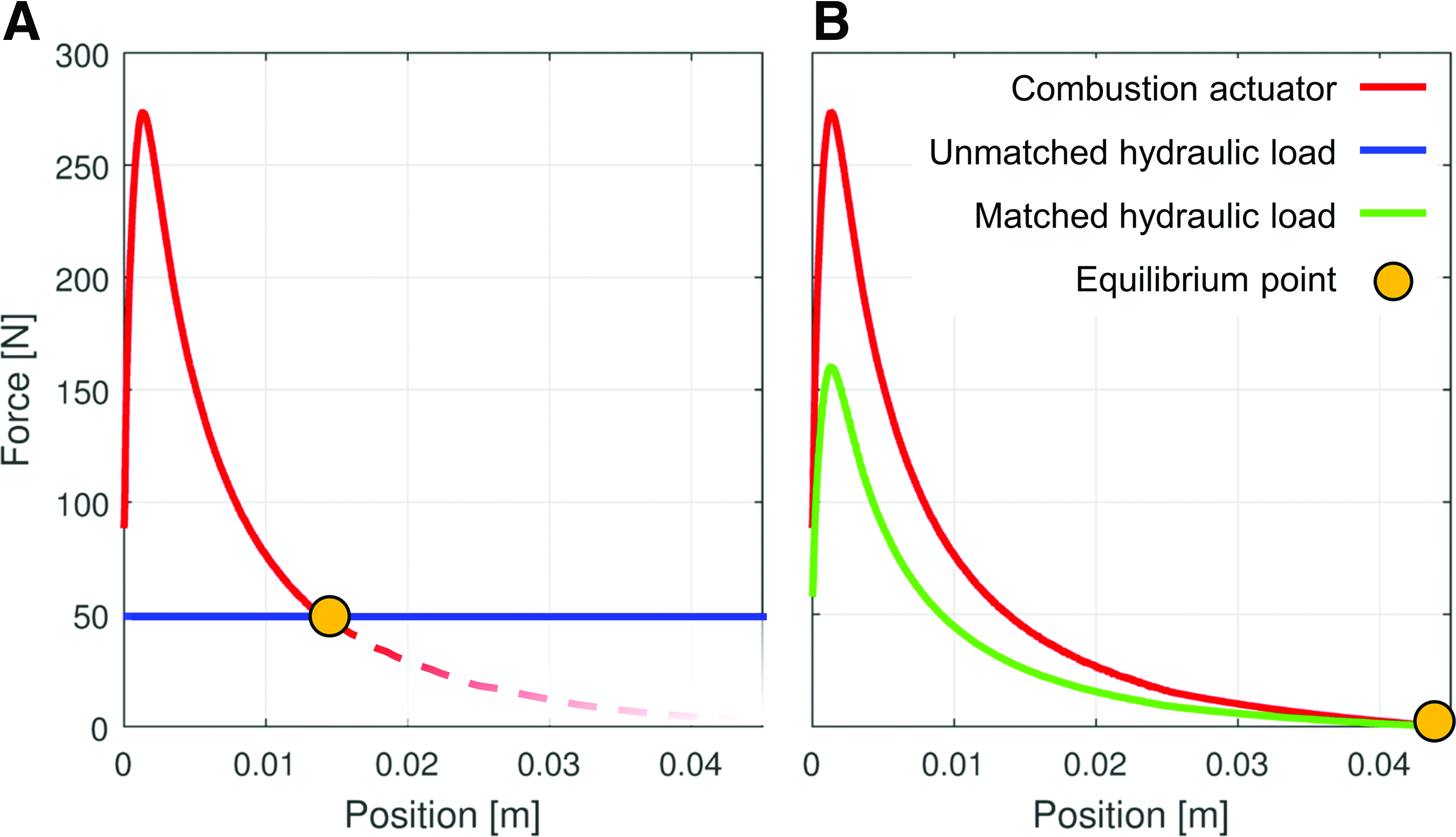
Simulated force profiles of the combustion-driven actuator compared with
Cam profile design
Using a load matching mechanism between the combustion-driven actuator and the hydraulic pump allows a continuous adjustment of the load throughout the pumping stroke and minimizing of the hydraulic losses.
A simple dynamic model of the load matching mechanism (Fig. 2) is given as follows:
where
The system dynamics are simulated in Figure 7 using Equation (12) with a typical pressure–volume trace extracted from experimental data (Characterization of the combustion-driven actuator section). Figure 7 shows the level of head loss is significantly higher when no cam is used, resulting in only 30% of the available work from the pressure–volume trace being extracted. Simulation with a cam increases this value to 65% due to a longer stroke and lower level of head loss.

Head loss through the check valve during simulation of a pumping stroke, with and without a cam mechanism. Color images available online at www.liebertpub.com/soro
As discussed previously, reducing the dynamics of the system introduces an efficiency trade-off between the hydraulics and the combustion actuator. This trade-off reflects on the cam profile design. As the cam is adapted for low dynamics, hydraulic efficiency will be better, but more heat and mass loss will occur in the combustion actuator. An optimal cam profile thus maximizes efficiency under given operating conditions. Finding such a cam profile depends on the application and is not the goal of this article, the focus of the article consists in a proof of principle of such a system.
Methodology
To evaluate the efficiency of the proposed combustion-driven, free-piston hydraulic pump, experimental tests are performed in two steps, using two different experimental tests benches. First, the efficiency of two combustion actuators (
Combustion-driven actuator
As shown in Figure 8, an experimental test bench is developed to investigate the effect of equivalence ratio, compression ratio, and dynamics on combustion actuator efficiency (

Experimental test bench used to evaluate the combustion actuator efficiency by measuring pressure, position, and force measurement.
Two combustion actuators, shown in Figure 9, are prototyped with the characteristics listed in Table 2 and used to study the effect of surface-to-volume ratio on efficiency. A first small-bore actuator (Fig. 9) consists of a steel combustion chamber head and a standard piston and cylinder assembly of 15.9 mm diameter (Clippard SDR-10-2). A second big-bore actuator (Fig. 9) is built in the same manner, but with a 31.8 mm diameter piston and cylinder assembly (Bimba 126-D).

Side view of small-bore
A sliding valve with relatively slow dynamics, yet good sealing, is used for both prototypes. The valve is driven by a pneumatic actuator and is placed as close as possible to the combustion chamber to reduce potential dead volume. Exhaust and intake ports are sealed using O rings.
The fuel–air equivalence ratio is controlled with two Alicat mass flow meters (MCR-1500SLPM-D/10M, MCR-250SLPM-D/10M). Hydrogen and air are mixed before intake through a tee-shaped pneumatic connector. The premix is allowed to flow freely 5 s before closing the valve, which ensures the scavenging of combustion products from the prior test. Compressed air is used to simulate gas compression and scavenging for all tests.
Once the valve is closed, the actuator is maintained at its initial position in a precompressed state using magnets. Rapidly decreasing force of magnets according to position allows a complete actuator stroke.
A miniature spark plug (Morrison and Marvin Rimfire Viper Z1) is used to initiate combustion. The dynamic pressure trace is measured with a high bandwidth piezo electric pressure transducer (PCB Piezotronics 105C12 SN 7956). The position is measured with a laser position sensor (Panasonic HL-G112-A-C5). Data acquisition is realized with a CompactRIO 9114 from National Instruments at a frequency of 10 kHz.
As detailed in Equation (1), the actuator efficiency (
The input energy (Ui) is obtained from the equivalence ratio φ, the fuel lower heat value
The input compression work (
Since readily available compressed air was used to perform the tests in this study, a representative value of compression efficiency of 65% is taken from experimental data of small centrifugal air compressors. 34 In addition, note that the scavenging work is neglected as it is expected to be low due to a split-cycle approach using external compression.
Combustion-driven hydraulic pump
As shown in Figure 10, a second test bench is used to evaluate the overall efficiency of the combustion-driven, free-piston hydraulic pump. In this test bench, the combustion actuator is linked to an aluminum cam mechanism through a load cell (Transducer Technique SBO-200) that measures the force output of the actuator. The bottom of the cam is guided by a ball bearing rail. The profiled surface of the cam is in contact with a small roller bearing that transmits forces to the input of a hydraulic pump.

Experimental test bench used for evaluating the efficiency evaluation of the combustion-driven, free-piston hydraulic pump.
The hydraulic pump is made out of a 19.1-mm diameter standard air cylinder (Bimba 043-DQ). According to Figure 10, a downward stroke of the pump sucks low-pressure hydraulic fluid through an inlet check valve (right). An upward stroke increases the fluid pressure until it reaches the cracking pressure of a regulating check valve (left) and the pressurized fluid is stored in an accumulator. Both check valves (Industrial Specialties Mfg. CVNNP-14) have a cracking pressure of around 6894 Pa (1 psi) higher than the output pressure of the valve. A pressure sensor (SSI P51-300A) monitors the pressure in the pump.
The accumulator consists of a 19.1-mm diameter acrylic tube linked to an 11-L pneumatic reservoir pressurized at 172,350 Pa (25 psi), ensuring a constant pumping pressure. The volume of fluid is measured with a graduated rule inside the accumulator after each stroke.
As represented in Figure 3, the overall (chemical-to-hydraulic) efficiency is defined as the ratio of overall net output work (WM) to the input chemical energy (Ui) from Equation (15). Here, the net output work is further defined as the measured pumping work in the accumulator (
Results and Discussion
Characterization of the combustion-driven actuator
Before assessing the efficiency of each piston, the effect of mass loss is estimated by pressurizing the combustion chamber and measuring the pressure decay over time. To do so, the small-bore device was pressurized at 1.6 MPa and a corresponding pressure decay of 0.3 kPa over 300 s resulted in an averaged leakage flow of 10e−10 kg/s. The big-bore device was pressurized at 0.8 MPa with a pressure decay of 6 kPa over 300 s for a leakage flow of 2e−7 kg/s. Dynamic simulations, including a choked flow model to account for previous amount of mass loss, showed such low leakage rates to have insignificant impact on efficiency. One must note that reducing equivalence ratio lowers the pressure in the combustion chamber, thus reducing the effect of mass loss on efficiency.
As often done in the large-scale engine community, Figure 11 reveals heat loss reduction due to lean hydrogen combustion, not by directly measuring heat fluxes, but by comparing pressure traces over volume for two combustion events. From ideal gas law, since the actuator has negligible mass losses due to leakage, any difference between the isentropic case and the experimental pressure trace is necessarily due to heat losses. In Figure 11, the left graph at a low φ = 0.3 shows that the experimental (blue line) and isentropic (green line) cases are very close to each other, while the right graph at a high φ = 0.6 shows a significant difference due to higher temperature and heat losses.

Pressure over volume for two combustion events with the same load and compression ratio of 2.5, but with different equivalence ratios. Left graph is at an equivalence ratio of 0.3. Right graph is at an equivalence ratio of 0.6. Red curves represent the isentropic input work from compression. Green curves represent an isentropic pressure curve corresponding to an efficiency of 37% for a compression ratio of 2.5. Blue curves are experimental pressure traces. Color images available online at www.liebertpub.com/soro
Figure 12 shows the impact of equivalence ratio and surface-to-volume ratio on actuator efficiency on a wide set of data. Efficiency decreases rapidly when equivalence ratio increases as combustion product temperature gets higher, causing higher heat losses. For the same equivalence ratio, compression ratio, and power stroke duration, the big bore reaches higher efficiencies again due to reduced heat loss due to smaller surface-to-volume ratio. As expected, increasing the compression ratio increases efficiency. Peak combustion actuator efficiencies (

Overall conversion efficiency for the small-bore actuator
Results suggest that lowering combustion temperature through low equivalence ratio is the critical parameter for homogeneous charge combustion systems to have any meaningful efficiency. Hydrogen is the only practical fuel that can burn in the range of equivalence ratio around 0.3 and is thus an enabler for such low-temperature mesoscale fuel power systems, may they ultimately be hydraulic, pneumatic, or direct acting. Methane and other hydrocarbon fuels are not effective as they will not even ignite below an equivalence ratio of 0.6. In fact, the practical lean limit of hydrocarbon fuels at small scale is likely to be above 0.6 because of combustion stability issues in cold air and low turbulence conditions. A significant observation is that everything else being equal, the results presented here show that efficiency roughly doubles when equivalence ratio reduces from 0.6 to 0.3.
Characterization of the combustion-driven hydraulic pump
The efficiency of the combustion-driven hydraulic pump is measured on five different cases using the small-bore combustion actuator. First, the actuator is directly coupled to the hydraulic pump and then coupled to four cams with different aggressiveness as shown in Figure 13.

Tested cam profiles. Color images available online at www.liebertpub.com/soro
For all experiments, fuel–air mixture conditions are set to the optimal conditions of compression ratio of 4.15 and an equivalence ratio of 0.3. Table 3 shows the experimental results obtained for various cam profiles, including power stroke duration (
Results demonstrate that using a cam can enhance the chemical-to-hydraulic efficiency of an otherwise direct drive setup by a factor of 8 × . It is also noticeable that efficiency decreases as the cam profile is further adapted for slower dynamics, resulting in a higher level of heat loss. In this study, a maximal efficiency of 4.6% is found with cam 2, which is a substantially higher efficiency than previously reported by other mesoscale soft robotic systems (Table 1). Comparing overall results from Table 3 (e.g., cam 2) with the performance requirements of various soft robotics systems synthesized in Table 1 (e.g., Harvard soft rehabilitation glove) and discussed in the Background—Untethered soft robotics section, it can be concluded that the combustion-driven hydraulic pump architecture presented in this article has the potential to match or even surpass the performance of the smallest electrically powered mesoscale soft robotic systems (∼10 W in size). Considering the practical storage energy density of hydrogen (6.12–9 MJ/kg) and the 4.6% system efficiency from Table 3, the overall hydrogen storage energy density of 0.28–0.41 MJ/kg compares favorably with the 0.07–0.14 MJ/kg electric storage energy density from practical mesoscale systems (Harvard glove, see the Background—Untethered soft robotics section). Even with the nonoptimized laboratory setup mass of ∼3.92 kg (actuator 500 g, valve 120 g, cam 100 g, linear guides 650 g, pump 150 g, accumulator 2400 g) and an estimated hydrogen storage mass of 40–60 g (for 2-h operation at 2.34 W output and 4.6% efficiency), the overall system energy density of ∼0.0042 MJ/kg is comparable with the 0.0037–0.0062 MJ/kg system energy density of the Harvard system (Background—Untethered soft robotics section). Moreover, by roughly extrapolating results to the big-bore actuator, which would provide ∼9.8% overall efficiency for ∼31 W or mean output power, it can also be concluded that the proposed approach is increasingly interesting for larger mesoscale soft robots (e.g., full exoskeletons) that require higher output powers (10–1000 W).
Conclusion
This article investigated the potential of a combustion-driven, free-piston hydraulic pump architecture for mesoscale applications in soft robotics. Specifically, the approach aimed at lowering combustion temperature with lean hydrogen–air mixture to allow combustion devices to operate efficiently in the time scales needed for efficient fluid pumping. Effects of enhanced heat and mass losses due to high surface-to-volume ratio and slow dynamics of mesoscale combustion-driven hydraulic pump were presented.
Two combustion-driven piston actuators were built and tested with hydrogen as fuel. The effects of compression ratio and equivalence ratio on chemical-to-mechanical conversion efficiency were studied experimentally. Results show potential for energy conversion efficiencies of 20% and 35% with a compression of 4.15, an equivalence ratio of 0.3, and assuming compression efficiency of 65% for the small-bore and big-bore actuators, which provide mean net powers of 26 and 197 W, respectively.
Using a load matching mechanism to couple the small-bore combustion-driven actuator with a hydraulic pump and accumulator system resulted in a single stroke chemical-to-hydraulic efficiency of 4.6% for 2.34 W mean overall output power, which is significantly higher than previously reported combustion-powered soft robotics of similar size. Efficiency is even more significant when extrapolating results to a big-bore combustion-driven actuator, which would provide overall system efficiency of ∼9.8% for a mean output power of ∼31 W.
The work provides the following conclusions and guidelines for mesoscale combustion-driven hydraulic pumps:
1. Hydrogen, due to its unique lean-burn ability, is an optimal fuel to reduce heat losses; 2. Compression ratio should be as high as possible to maximize efficiency. 3. The expansion-to-compression ratio should be as high as possible to maximize efficiency and reduce the noise level. 4. A load matching mechanism should be used to adjust the dynamic of the pumping stroke to reach optimal energy transfer efficiency.
Altogether, the overall efficiencies, flow rates, pressures, and powers achieved in this work indicate that the technology has the potential to match or surpass the performance of electrically powered mesoscale hydraulic systems (e.g., soft rehabilitation glove) that require ∼10 W or more of power to operate. The high combustion efficiencies (20% and 35%) also suggest that the use of hydrogen could also significantly improve the efficiency of direct-acting soft robot combustion. The presented work is a laboratory proof of concept. Future work should thus be devoted at conducting a system-level optimization, developing practical solutions for air and fuel management as well as valve actuation, and testing a fully functional mesoscale soft robot using a hydrogen-powered hydraulic pump.
Footnotes
Acknowledgments
This work has been supported by the Ingénierie de technologies interactives en réadaptation (INTER) group, the Fonds québécois de la recherche sur la nature et les technologies (FRQNT), and the Natural Sciences and Engineering Research Council of Canada (NSERC).
Author Disclosure Statement
No competing financial interests exist.