




Abstract
Abstract
Substantial device mass and control complexity can hinder the impact of wearable robotic technologies, such as exoskeletons. Thus, despite promising previous research, the development of a simple, lightweight actuator for these systems has not yet been fully realized. The purpose of this study was to derive and demonstrate a proof-of-concept for a pneumatic interference actuator (PIA)—a lightweight, soft actuator able to produce torque by the self-intersection of a fabric balloon that arises from changes in physical geometry. General closed-form equations are derived to express the expected actuator torque and mechanical work as functions of the balloon geometry, pressure, and deflection angle. Hard and soft cylindrical physical prototypes were constructed to assess the accuracy of the mathematical models. The proposed mathematical model was found to agree with the pressure–volume relationship and successfully predict the maximum torque as a function of geometry, pressure, and deflection at nonzero deflection angles. Peak powers up to 122.1 ± 10.0 W (mean ± standard deviation), with a resting internal pressure of 158.0 ± 0.2 kPa, were observed from the hard actuator prototype. For the soft actuator prototype, peak powers of 97.9 ± 21.1 W were observed at a resting pressure of 166.8 kPa. The work performed was within 3.2% ± 3.4% and 14.4% ± 8.2% of theoretical values across all trials, and within 19.1% ± 4.4% of theoretical values when compared to the torque–angle relationship. This study highlights the promise of utilizing the self-intersection of a PIA to perform human-scale mechanical work, and future research will focus on implementations for wearable robotic systems.
Introduction
W
One important limitation is often the mass and rigidity of actuation technologies used in wearable robots.11–13 Electromechanical actuators, such as brushless DC motors, are traditionally used with metal support structures, transmissions, and bearings, all of which can increase the mass and complexity of these technologies. The electric motors typically used in many wearable robotics applications often have a specific power of less than 1 kW/kg. 14 Human joints provide powers on the order of tens to hundreds of mechanical watts, thus wearable robotic technologies can weigh several kilograms. Added weight is problematic for mobility, since it is known to increase metabolism and decrease comfort, especially when worn distally. 15 Moreover, weight is especially critical for rehabilitative assistive technologies, since the metabolic burden caused by these technologies is the greatest predictor of their abandonment. 16 Rigidity can also decrease comfort; modern gait exoskeletons typically utilize fixed axes of rotation through mechanical bearings and structures. The centers of rotation of anatomical joints must be carefully aligned to the mechanical axes of the mechanisms, and misalignment causes further unwanted loading and strain. 17 Thus, the specific power, mass, and rigidity of current exoskeleton technologies may be a barrier to their widespread impact.
Soft robotic actuators have the potential to reduce mass and rigidity while improving the comfort of wearable robotic technologies. Soft actuators generally forgo traditional rigid structural elements and instead implement lightweight, flexible components, which have had recent success in wearable robotic applications. For example, Asbeck et al. have developed a soft “exo-suit” that applies locomotor assistance through tendon-like Bowden cables driven by electric motors worn on the back.18,19
An alternative approach to soft electromechanical systems is the use of pneumatic elastomeric actuation. These soft actuators use high-strain elastomers and apply mechanical power through the inflation of extensible pneumatic bladders.20,21 The bladders inflate with differing ratios or include interwoven layers of inextensible fibers. 20 The inflation of these soft actuators causes predictable changes in mechanism geometry based on strain in the elastomer, which can be tailored to specific kinematic patterns, such as finger flexion. 22 Elastomeric actuators provide the benefits of pneumatic power; however, they are often difficult to design quantitatively. Development of soft actuators through a quantitative approach is an emerging area of research,23–25 although the mechanical power and torque obtainable by these systems are below what would be required to mimic the mechanics of human locomotion.
McKibben actuators or “pneumatic muscles” have provided an innovative method for lightweight exoskeleton actuation, 26 however, these technologies forgo many of the advantages of soft robotic systems. Gordon and Ferris developed an ankle exoskeleton powered by McKibben actuators to study how neural activation changes while walking with assistance. 27 In addition, Sawicki and Ferris used a similar device to study how exoskeleton power effects the biomechanics and metabolism of gait. 28 These systems have provided a lightweight opportunity to investigate control strategies for wearable robotics, which has enabled much needed insight for the field. They utilize the lightweight and high-power characteristics of pneumatic technology; however, they are linear mechanisms by nature, rather than rotary. Consequently, they require metal or composite structures and bearings to serve as a transmission that converts linear motion into rotary motion. To mitigate the transmission, Sanan et al. previously developed a torsional pneumatic actuator using two opposing helixes,29,30 or cable operation of inflatable links, 31 which continues to be an active area of research. Finally, although not developed for mechanical actuation, previous researchers have investigated inflated beams as structural elements,32–36 which provided an important mathematical foundation.
In addition to the benefits of soft and lightweight technologies, simple mechanisms have advantages for the success of wearable robots. To this end, a principle known as “embodied intelligence” may be leveraged. Embodied intelligence is used to produce a desired mechanical behavior that results purely from the mechanism's physical form and intrinsic mechanical properties, as seen in works by Connolly et al., Kim et al., and Cianchetti et al.24,37,38—it has been proposed that the “control intelligence” can be designed into the structure itself (see also “morphological computation”39,40). Using the principles of embodied intelligence, the geometry or other physical aspects of a device may be derived specifically to create a useful, sometimes complex, response from a simple input that does not necessitate extensive closed-loop control. In a similar way, previous work on shape memory alloys and polymers has used electric current and other stimuli to produce a desired strain. 41 Previous research has produced clever mechanisms that can reproducibly fold into robotic origami without complex control schemes. 42 This approach has also been applied to pouch motors for linear and rotational actuation. 43 Embodied intelligence is an exciting design and control approach for wearable robotics; however, the power and torque provided by these systems have remained too low for human locomotor applications.
In this work, we leverage the benefits of soft robotic actuation within the framework of embodied intelligence to develop potentially simple, lightweight, and low-cost actuators. The intent of this class of actuators is to provide a new opportunity for wearable robots (e.g., exoskeletons that assist with ankle push off), including providing the torques and powers required to assist human locomotion. We introduce an actuator based on the self-intersection of an inextensible fabric balloon, termed a pneumatic interference actuator (PIA). We derive a general mathematical model based on a desired torque–angle relationship and assess the model with two cylindrical physical prototypes. The PIA presents the opportunity to use embodied intelligence because the mechanics can be specified a priori by defining the shape of the balloon structure, and how interference occurs as a function of angular deformation. Future work will focus on the development of PIAs with more elaborate geometries and wearable robotic technologies that implement these actuators. Beyond refinement of the mathematical model, device design, and fabrication, further investigation on efficient energy storage will also be required to maximize the benefits of this class of actuators.
Methods
Actuation principle: PIA
The soft actuation concept presented in this work is based on the self-intersecting mechanics of an inextensible fabric balloon. To illustrate the mechanics of a self-intersecting balloon, consider the buckling cylindrical balloon shown in Figure 1. As a bending moment is applied to the fabric balloon, buckling occurs and the geometry changes: a crease is formed in the center of the balloon, and the two halves of the balloon begin to self-intersect (Fig. 1A, B). As the deflection angle increases, more resistance torque is created, leading to a “spring-like” mechanical behavior. The increase in torque is caused by an increase in internal pressure within the balloon, resulting from the decrease in volume as the geometry self-intersects. The spring-like mechanics can be activated and deactivated by inflating and deflating the balloon in the appropriate configuration. When deflated, the balloon has no mechanical behavior or resistance (i.e., loose cloth), and when inflated the balloon is spring like. By carefully designing the shape of the balloon a priori, a desired torque–angle relationship can be specified as a function of balloon configuration. The torque provided is governed by the design of the shape of the balloon and the internal pressure. By designing how the shape intersects during buckling, arbitrary mechanics (torque–angle profiles) can be created. The governing equations are derived in the following sections.

An example PIA is shown
Generalized governing equations
To quantify the mechanics of the PIA, a closed-form expression for torque in terms of geometrical parameters and deflection angle was developed. These equations are general and make a few assumptions on balloon shape, cross section, or desired torque–angle behavior—mainly that the desired torque–angle mechanics is monotonically increasing. We begin from an analysis of the work, W, done by the system, which can be expressed by a relationship between internal pressure, P, and volume, V, as well as between torque, τ, and deflection angle, θ (Fig. 2).

Annotated actuator diagram. The soft actuator in self-intersecting (State 1) and rest (State 2) configurations. A qualitative representation of the midline crease (dashed line) is shown in State 1 diagram. The shaded area indicates the region of intersection, from which the change of volume is derived as a function of angle. Color images available online at www.liebertpub.com/soro
Using knowledge of how the inextensible balloon intersects during buckling, an equation for volume as a function of deflection angle can be obtained,
With both expressions sharing the same variable and limits of integration, the integrands can be equated. This allows for torque to be expressed in closed form.
Assuming the balloon must always expand against the atmosphere, atmospheric pressure, Patm, is subtracted from the instantaneous internal pressure, P1, in the pressure function. This subtraction removes the portion of the pressure–volume work that cannot be used for torque production, yielding the final form of the general expressions for work and torque as functions of pressure and angle.
This general technique can be used to quantify work [Eq. (4)] and torque [Eq. (5)] for any arbitrary balloon geometry, where the volume can be expressed as a function of deflection angle. By choosing different geometrical parameter values (that alters the relationship between deflection angle and volume change) the torque–angle curve can be modified to produce a desired profile.
Governing equations for cylindrical prototype
For simplicity, our preliminary studies focus on a cylindrical prototype of the PIA. As shown in Figure 1, torque causes the balloon to buckle in the center, orthogonal to the long axis (forming the crease). The rise in internal pressure creates the restorative torque about the center of rotation. In our analyses, “State 1” signifies when the PIA is deflected at any angle, θ, and “State 2” signifies when the actuator is at its final, unbuckled state (Fig. 2). Consequently, the internal pressures of the actuator at “State 1” and “State 2” are denoted P1 and P2, respectively.
The volume of the cylindrical balloon at buckling angle, θ, can be found using the following expression, where r is the radius of the cylinder, assuming negligible material strain (i.e., inextensible balloon).
The volume expressed here is calculated by taking the difference between the unbent volume,
To determine the mechanical work performed by a given configuration, the closed-form expression for torque [Eq. (7)] can be integrated over the range of angular deflection, θi through θf.
Prototype design
Following the derivation of the mathematical model, physical prototypes of the PIA were constructed to validate the framework for the mathematical expression for torque. The initial prototype was constructed to have a partial hard shell, composed of rigid PVC caps that enforced the circular cross-section assumption. This also aided in prototype construction and allowed for valves and sensors to be easily integrated. Two schedule 80 PVC caps (Model No.: 4880K14; McMaster-Carr, Elmhurst, IL) were cut at a 15° angle to accommodate the pliable material (e.g., fabric) that constituted the self-intersecting region (Fig. 3). The material used for the flexible region was a Mylar film that had a thickness of 0.120 mm, sourced from the same material used to construct Kettle brand potato chip packaging. A sheet of this Mylar film was sealed into a cylindrical loop, with a radius of ∼36 mm, using an impulse sealer to provide a thermal weld (Model No.: IMS12; Bag-N-Seal, Emmeloord, NL). The loop of Mylar film was fastened to the interior surface of each PVC cap using hot melt adhesive.

Soft actuator prototype. An early prototype of the soft actuator concept, pictured in State 1 (left) and State 2 (right). The prototype uses rigid PVC to maintain the circular cross section. Color images available online at www.liebertpub.com/soro
Peripheral components were integrated with the prototype to allow for inflation and data acquisition. A wye component (Model No.: 7880T316; McMaster-Carr) was threaded into one PVC cap and used to connect tubing for inflation and pressure measurement (Fig. 3). A plastic cover was epoxied to the end of the prototype to permit insertion of a rod to apply load. An electrogoniometer (S700 Shape Sensor; Delsys, Boston, MA) was mounted on each side to permit collection of angle data.
An additional, fully soft prototype was constructed using the Mylar film and a Schrader valve. The ends were sealed using the impulse sealer and the Schrader valve was bonded to the plastic film using hot melt adhesive. This prototype was capable of achieving the range of inflation pressures experienced by the hard prototype during data acquisition. A second version of the soft prototype was created that was covered with polyester fabric for stress relief (Fig. 4).

Soft actuator prototype with and without polyester stress relief envelope. Version with polyester envelope annotated with device length, height, and cross-sectional diameter. Color images available online at www.liebertpub.com/soro
Mechanical characterization
The actuators were characterized with a data acquisition system able to measure torque, pressure, and angle data. The PIA was mounted to a six-axis load cell (Model No.: 45E15A M63J; JR3, Woodland, CA) to measure applied forces and moments. Pressure sensors were used to record how pressure varied during angular deflection (Model No.: SSCDLNN100PGAA5; Honeywell, Morristown, NJ, and Model No.: DT105 Pocket Digital Gauge; Pressure, Inc., Nashville, TN). The pressure sensor was used to record pressure data continuously during experiments, and the digital gauge was used to set the resting pressure during inflation. The range for the pressure sensor was 0–690 kPa, and the accuracy was within 0.25% full-scale range, or 1.7 kPa, including all errors from nonlinearity, hysteresis, and nonrepeatability. The deflection angle was monitored by the electrogoniometer mounted to the device orthogonal to the axis of bending. A manual goniometer was used as an independent reference measurement to calibrate the electrogoniometer (sensitivity: 0.6475 rad/V). Data were collected with an experimental setup using MATLAB xPC Target (The MathWorks, Natick, MA), a 16-bit analog-to-digital converter, and a sampling rate of 2.5 kHz (National Instrument, Austin, TX). For cyclic torque–angle testing, the data were filtered using a second-order Butterworth filter with a cutoff frequency of 5 Hz. Due to the higher frequency elements present in the mechanical power response, a cutoff frequency of 30 Hz was used.
Testing protocol
The reaction torque for the PIA was measured as a function of angle for pressures between 131 and 158 kPa absolute pressure. The torque–angle mechanics of the actuator was recorded for each 2-min trial. During each trial, a torque was slowly applied to the actuator to induce ∼35° of deflection (Fig. 5). The actuator was then slowly returned to its resting (unbuckled) geometry, and the process was repeated cyclically for the duration of the trial. The magnitude of the applied moment was determined by performing a transformation on the load cell data to the actuator's approximate axis of buckling.
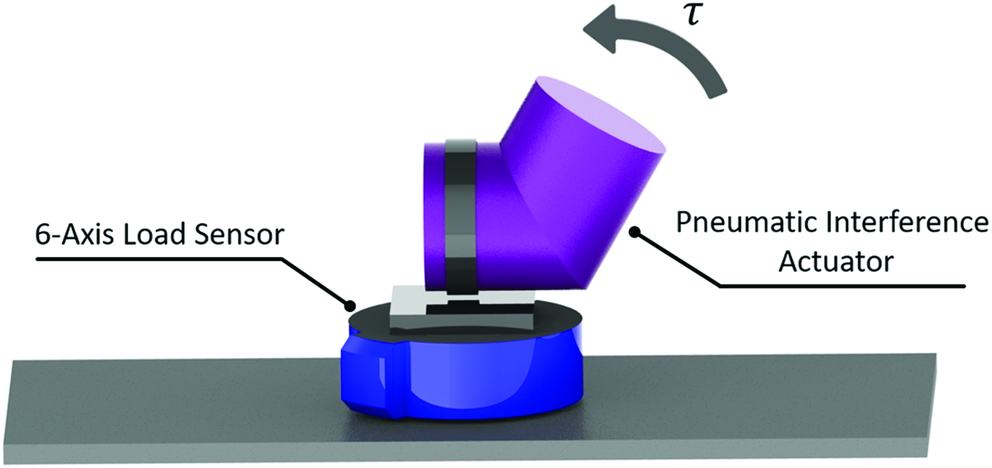
Torque measurement setup rendering. This rendering depicts a simplified representation of the torque testing setup, with key elements labeled. Color images available online at www.liebertpub.com/soro
The final testing procedure characterized the mechanical power of the PIA. To test the hard prototype version, a 317 g weight was fixed to the free end of the actuator. Each trial consisted of 5 s of data collection and five trials were completed, at each of five resting pressure levels (122.7–158.0 kPa). For the soft prototype, a mass of 345 g was used and five trials were completed at resting pressures of 146.1 and 166.8 kPa. A larger mass and shorter moment arm were used because of the compliant nature of the soft prototype. The weights were selected based on their availability, rather than the precise magnitudes of their masses. Each trial was initiated with the actuator at State 2 and no manual load applied. The actuator was then deflected in the horizontal plane to an angle of ∼15°, released, and allowed to expand to equilibrium through unconstrained angular acceleration. The transformation from the previous procedure was used to convert the load cell data to torque about the actuator's axis of buckling. This was similar to storing and releasing energy from a compressed torsion spring.
The power produced by the PIA was calculated from the torque and angle data collected during each trial. The angular velocity of the actuator was found by numerically differentiating the angle data. The power data were calculated using Eq. (9) with the empirical torque data, τ, and the corresponding angular velocity values, ω, derived from angular position data.
Data processing
The work performed was found using both the torque–angle and pressure–volume profiles for each cyclic trial. To calculate the magnitude of pressure–volume work, the portion below atmospheric pressure was subtracted from the integrated area, as it was in the mathematical derivation [Eq. (4)]. Because there is no direct measurement of internal volume, it was inferred using the geometric relationship between angle and volume [Eq. (6)], as well as using Boyle's Law. To distinguish between the two volume calculations, these pressure–volume work calculation methods are referred to as “Empirical #1” and “Empirical #2,” respectively. The torque–angle evaluation was performed using empirical torque data, as well as theoretical values based on resting pressure. For each trial, best-fit lines were generated from each data set and used for subsequent integration to calculate work (area under the torque–angle and pressure–volume curves). A fifth-order polynomial was fit to each empirical torque–angle data, third-order (Empirical #1) and second-order polynomials (Empirical #2) were fit to the empirical pressure–volume data, and third-order polynomials were fit to the theoretical data (both torque–angle and pressure–volume). The orders of these polynomials were selected to adequately represent the trajectories produced by the data. The accuracy of each theoretical work model was assessed by expressing the difference between empirical and theoretical values as a percentage of the theoretical value. The same polynomials were used to quantify the average error between the theoretical and empirical torque to assess the accuracy of the closed-form expression derived for torque. The hysteresis observed during testing was calculated by finding the area inside each torque–angle loop. The mean and standard deviation of these integration differences were computed for each torque trial. In one trial, the final deflection did not complete a full cycle and was omitted from the hysteresis analysis.
Mechanical power [Eq. (9)] for each trial was truncated to remove the initial setup period (deflecting the actuator). Data were resampled to be a function of percent stroke. Peak power was the maximum value observed during unconstrained acceleration.
Results
Torque–angle
The results of a representative trial using the hard prototype PIA (resting pressure of 144.8 kPa) are provided, with torque shown as a function of angle (Fig. 6A). During this trial, a maximum torque of 11.2 Nm was recorded at an angle of 33.9°. The soft prototype PIA, when tested with a measured resting pressure of 146.1 kPa, produced a maximum torque of 7.3 Nm at an angle of 38.6°.

Torque–angle relationships are shown for two prototype versions. Graphs depict
Hysteresis was present in the cyclic torque–angle trajectory across all pressures and both hard and soft prototypes. The hysteresis magnitude is monotonically increasing across resting pressure levels for each version of the PIA, with the highest mean hysteresis, 2.8 ± 0.59 J, occurring at a resting pressure of 167 kPa using the soft shell prototype. Across all trial pressures for the hard shell prototype (1.31–1.58 × 10⁵ Pa), mean hysteresis of 0.1–0.4 J with standard deviation of 0.04–0.06 J was calculated. For soft shell prototype trials (1.46–1.67 × 10⁵ Pa), mean hysteresis of 1.4–2.8 J with standard deviation of 0.24–0.59 J was calculated.
Pressure–volume
The instantaneous pressure throughout each trial is shown as a function of measured change in volume (Fig. 7), which was determined using the electrogoniometer data and the derived volume relationship [Eq. (6)]. The instantaneous theoretical pressure, as predicted by the resting pressure and deflection angle, was plotted with the empirical data.

Pressure–volume relationship at various resting pressures. Two empirical curves (gray) and one theoretical curve (black) are shown for the hard prototype at varied pressures. Empirical #1 lines (solid gray) show P1 (measured) plotted against volume change [calculated using Eq. (6)]. Empirical #2 lines (dashed gray) show P1 (measured) plotted against volume change (calculated using P1, P2, Boyle's Law, and initial volume). Theoretical lines (solid black) show P1 [calculated using P2, Eq. (6), and Boyle's Law] plotted against volume change [calculated using [Eq. (6)].
For all trials, the magnitude of predicted and empirical work was calculated using the pressure–volume and torque–angle curves. The empirical values were compared with the corresponding theoretical value at each pressure level, with the differences between theoretical and empirical results expressed as percentages of the empirical values (Table 1). The empirical work measured using the pressure–volume curve was within 3.2% ± 3.4% (mean ± standard deviation) of the anticipated magnitude across all trials for Empirical #1, and within 14.4% ± 8.2% for Empirical #2. When measured from the torque–angle curve, the work varied from the anticipated magnitude by ∼19.1% ± 4.4%.
P-V, pressure–volume.
Power
The peak power was calculated for all five hard prototype PIA trials at each inflation pressure. The mean peak power production was plotted for each resting pressure (Fig. 8A, B), as was the mean power stroke (with shaded standard deviation) for resting pressure of 158 kPa (Fig. 8C). At a resting pressure of 158.0 ± 0.2 kPa, peak power of 122.1 ± 10.0 W was observed. For these trials, the deflection angle was ∼38.3 ± 1.0° at the time of release. The fully soft prototype PIAs with and without a polyester cover (Fig. 4) were weighed for calculation of specific power measurement, and had masses of 35 and 17 g, respectively. For a mean peak power of 122.1 W, and a mass within this range, the actuator has a specific power of 3.5–7.2 kW/kg when inflated to 158.0 kPa and deflected 38.3°.

Peak power results. Bar graphs depict mean peak power values for
Discussion
Wearable robots often use electromechanical actuators and rigid support structures to perform mechanical work and assist the user. One potential drawback to this approach is the mass and complexity can sometimes arise, which can increase the metabolic cost of operation, reduce user comfort, and may ultimately contribute to device abandonment. The goal of this work is to investigate the viability of the PIA—a soft, rotary actuator that may be able to provide physical assistance during gait while maintaining a low mass. While electromechanical motors are well suited for many applications, reduction in mass may be beneficial for wearable robotic applications. With the proposed PIA, actuation is achieved through the inflation of a self-intersecting balloon that is constructed from inextensible material or fabric. A mathematical model was derived to describe bucking mechanics, the goal of which was to enable a quantitative design process to be used when developing soft robotic actuators.
Quantitative framework and embodied intelligence
The mathematical model derived in this study successfully described the mechanics of the PIA. For an inflation pressure of 144.8 kPa, the average torque error of 1.7 Nm was 15.7% of the peak torque, 11.1 Nm. Thus, there is an opportunity to quantitatively design the PIA using the equations presented. To vary torque–angle profile nonlinearly, changes of shape or radius as a function of length may be used in conjunction with an optimization analysis (Fig. 9). For example, once the desired torque–angle mechanics is chosen (Fig. 9A), Equations (6) and (7) may be used to optimize a balloon shape (Fig. 9B) that matches this mechanics as closely as possible when deflected (Fig. 9C). The desired torque–angle trajectory and resting pressure can be used as optimization inputs, and the output of the analysis could be the theoretical balloon shape. Using such a framework enables a quantitative design process to be implemented in the development of novel PIAs. This is the focus of future work.

Qualitative design workflow. Representative diagrams show the development of a PIA from
For tasks with known and cyclic mechanics (e.g., human locomotion), the actuators could be designed to provide the mechanics of gait by virtue of their physical configuration, potentially without the need to servocontrol torque. The “control” of torque could then be provided by simply designing the appropriate shape of the PIA. This opportunity is afforded by the premise of embodied intelligence and is particularly useful for cyclic tasks, such as human locomotion.
Theoretically, the mathematical model predicts a “preload” as a function of internal pressure. When the PIA is pressurized above atmospheric pressure, the mechanism behaves as a spring that is precompressed. That is, in theory, some nonzero torque is required to cause deflection from the rest position (Fig. 6A). This preload can be observed in Equation (7) when θ = 0, where the offset in Nm is
Performance within a soft framework
The specific power of the PIAs highlights their promise for use in wearable robotic applications. The PIAs used in this study were operating at pressure well below those typically used for McKibben actuators, which underscores their potential to operate at greater specific powers, if able to withstand higher pressures. A key difference, and active area of study, is the development of pneumatic power sources, which may reduce the specific power for the total system (see the Limitations section).
Suitability for wearable robotics
The PIA may be well suited for use in wearable robots due to the unidirectional operation and ability to deflate when not actively providing power. While unidirectional actuators are sometimes less optimal than bidirectional solutions, they have advantages for applications in wearable robotics, particularly those pertaining to the lower limbs. Previous work by Mooney et al. used a unidirectional actuator in an ankle exoskeleton that reduced the metabolic energy required for walking.4,45 The unidirectional nature permits the mechanism to “get out of the way,” where low-output impedance prevents the mechanism from interfering with the operator when the mechanism is not providing assistance. Thus, by deflating the balloon between actuation cycles, the resistance of the actuator is negligible and it may not restrict the movement of the wearer. This attribute is unique from many traditional rigid actuation mechanisms that have the potential to impede the user's biomechanics by introducing unwanted resistance. Finally, the presented PIA is rotary by nature. Thus, no linkages or bearings are required. Furthermore, the presented class of actuator (PIA) has the potential for “human-scale” torque, meaning that no transmissions would be required to increase output torque to a magnitude useful for wearable applications. These attributes may permit advantages in efficiency, complexity, and mass.
Simplicity and low cost
Beyond the performance of this actuator, the materials from which it is fabricated are unique in their availability and affordability. Robotic actuation mechanisms can be expensive and may require sophisticated manufacturing and assembly processes with tight tolerances. 43 The materials used to create these prototypes are extremely inexpensive (e.g., Mylar film acquired from potato chip bags). The fabrication process utilizes minimal specialized equipment, requiring an impulse heat sealer, sewing equipment, and hand tools. The absence of expensive or specialized machinery for tight tolerances serves to reduce the final cost of manufacture and assembly of these actuators, which will broaden their range of feasible applications. While large-scale production of refined actuators following this concept would require expanded infrastructure and manufacturing, it is still expected to be an economical process capable of producing affordable actuators. Finally, these are characteristics of the broad class of PIAs envisioned to contain many potential geometries and mechanics, implications beyond the specific prototypes presented in this work.
Limitations
There are two primary causes for the disparity between the empirical data and predictions of the mathematical model, both related to the shape of the closed volume during buckling. The first potential cause is the material from which the actuator was constructed was not totally inextensible; the Mylar film likely undergoes some strain during the deflection process. This allows the deflection angle to increase without a substantial reduction in the internal volume of the cylinder, hence the difference between the Empirical 1 and Empirical 2 calculations for volume (Fig. 7). The second possible cause for the discrepancy is that the balloon may not maintain the intended cross-sectional shape during buckling. As buckling occurs, the cross section may flatten, leading to an “oval-shaped” cross section. This contrasts with the circular cross section assumed in the mathematical model, which causes a lower volume reduction per unit of angular deflection. This effect may be more prominent for the soft version of the actuator because it does not have any rigid components to enforce the circular shape of the cross section. Future work is needed to understand the effect of these factors on the mathematic model used for design.
The hysteresis in the soft prototype may reduce the mechanical work able to be used from the actuator (Fig. 6). The hard prototype had minimal hysteresis, indicating that much of the energy would be provided to the user if the PIA was inflated from a self-intersecting position. However, in the soft version, much of the energy is dissipated by the material, leading to less that could be applied by the actuator. A significant portion of this loss may result from friction between the interior Mylar layer and the outer fabric layer that comprises the stress relief envelope. The use of a dry lubricant may reduce the friction between these layers to diminish hysteresis resulting from energy dissipation. Future work is needed to fully characterize the hysteresis and mitigate its effects.
The power measurement procedure used in this study was limited to the deflection and release of the actuator in a preinflated state. That is, instead of evacuating and filling the volume with each cycle, the system was released from a pressurized state. This protocol does not enable quantification of the delay that may be associated with filling the actuator with pressurized gas during use. Future work should include testing with a power supply, valve, and control system. Investigation of PIAs during inflation is also important because extreme deflection angles of uninflated PIAs may restrict airflow, producing unanticipated behavior.
Construction of PIAs with noncircular cross sections, as proposed in this discussion, could present challenges with respect to geometric adherence to the intended shape. An inflated volume composed of compliant material will naturally trend toward a circular cross section with even pressure distribution. Thus, certain cross-sectional shapes or internal pressures may be impractical due to the natural physics of balloon inflation.
One potential advantage for the PIA is the ability to reduce reliance on closed-loop control; however, this is only applicable if the desired actuator mechanics is torque–angle in nature. That is, if the actuator's torque is desired to be purely a function of actuator angle. This control approach has shown promise in wearable robotic applications, such as those developed for exoskeletons and robotic prostheses. However, if the desired actuator mechanics is a function of time or some nonangular phase, closed-loop servocontrol would still be necessary.
Finally, just as electric motors require batteries to supply power, operation of this class of actuator is contingent on a pneumatic energy source. There are several potential pneumatic energetic sources, with varying degrees of suitability for wearable robotic applications. Pneumatic energy can be provided by a compressor, gas storage canister, or a chemical reaction. Use of a compressor requires an additional actuator to drive the compressor, which may limit the efficiency and power-to-weight potential of the complete system. A composite canister of compressed gas, such as carbon dioxide, could potentially provide a lighter, more portable solution with the drawback of having a finite energy, and relatively poor energy density. Chemical reaction-based pneumatic energy may be a promising path to develop autonomous pneumatic actuators. Previously, hydrogen peroxide (monopropellant) was used as a fuel in other robotic actuators46,47 and may be compatible with the PIAs. This is an active area of study that spans many fields.
Conclusion
Through the use of the PIA concept, there may be an opportunity to develop novel actuators for wearable robotic applications. Reduction of actuator mass and the use of a soft, inflatable framework may improve user comfort and reduce metabolic burden, consequently helping to reduce device abandonment. An embodied intelligence approach may enable the reduction of device complexity, and control may be designed into the actuator shape. Finally, the practical advantage of low-cost materials and simple manufacturing requirements may further add to the suitability for assistive wearable robots. Substantial future work is needed to address the limitations of this study, including pneumatic energy supply, and disagreement between the theoretical and actual models.
Footnotes
Acknowledgments
We thank Prof. Carl Lira for discussions on matters of thermodynamics, and Amcraft Manufacturing (Elk Grove Village, IL) for supplying materials used in prototype generation.
Author Disclosure Statement
Tim Swift holds an equity stake in Roam Robotics, a company that produces pneumatic exoskeletons. No other competing financial interests exist.