
Abstract
Abstract
A pneumatically powered, reconfigurable omnidirectional soft robot based on caterpillar locomotion is described. The robot is composed of nine modules arranged as a three by three matrix and the length of this matrix is 154 mm. The robot propagates a traveling wave inspired by caterpillar locomotion, and it has all three degrees of freedom on a plane (X, Y, and rotation). The speed of the robot is about 18.5 m/h (two body lengths per minute) and it can rotate at a speed of 1.63°/s. The modules have neodymium-iron-boron (NdFeB) magnets embedded and can be easily replaced or combined into other configurations. Two different configurations are presented to demonstrate the possibilities of the modular structure: (1) by removing some modules, the omnidirectional robot can be reassembled into a form that can crawl in a pipe and (2) two omnidirectional robots can crawl close to each other and be assembled automatically into a bigger omnidirectional robot. Omnidirectional motion is important for soft robots to explore unstructured environments. The modular structure gives the soft robot the ability to cope with the challenges of different environments and tasks.
Introduction
S
We derive inspiration from caterpillar motion to build a modular omnidirectional soft mobile robot. Robots are expected to have the following characteristics: (1) they should be omnidirectional, which means that they should be capable of not only moving forward and backward as well as left and right but also have a rotatory motion, (2) robots should be made up of different modules, which means that when one of the modules is damaged, we can replace the damaged module instead of the whole robot, and (3) robots should be able to be reconfigured into different task-based forms.
Inspiration from caterpillars
Caterpillars exhibit different strategies for locomotion: (1) inching: this strategy is seen more often in small and thinner caterpillars. Caterpillars move forward almost one body length and form a body loop that looks like an “Ω”. (2) Crawling: this strategy is mainly seen in the larger and thicker caterpillars. Both legs of legged body segments are lifted and moved forward simultaneously. Caterpillars move forward by propagating waves of steps initiated at the posterior of the body and end at the thoracic legs. (3) Other types of locomotion: other short-term locomotion strategies are mainly used to escape, including rolling, thread-climbing, backward locomotion, and galloping. 23 The unique motion gaits of caterpillars have been mimicked by several robots, such as GoQBOT reported by Lin et al. 21 to perform the inching, crawling, and rolling form of caterpillar locomotion and nonpneumatic crawling robots.24–26 Deng et al. 22 described a novel soft machine table for manipulation of delicate objects with an inverted caterpillar locomotion approach. McHugh et al. 27 proposed a decomposition method that simplified the design problem of a high degree-of-freedom (DOF) soft robot and built a caterpillar-like soft robot. Saunders et al. 28 used a lumped dynamic model to design and optimize the gait of a caterpillar-like soft robot.
Modularization strategy
The strategy of modularization has been widely used in building hard robots. 29 Some researchers have applied this strategy in the production of soft robot for the following benefits: (1) lower financial costs: only the damaged or contaminated modules of the soft robot have to be replaced, instead of scrapping the whole robot; (2) shorter time costs: different material, size, structure, and function of the soft actuators can be combined to achieve the new features; (3) better adaptability: modules can be reassembled into different forms of robots to meet the requirements from the environments and tasks. Kwok et al. 30 reported reconfigurable soft actuators that were self-aligning with embedded magnets, which could be used to assemble a hybrid hexapedal robot. The robot was capable of different tasks, such as remote assembly and disassembly of its actuators. Nemitz et al. 31 introduced a modular worm-like robot actuated by voice coils, which could be quickly and easily assembled into any length.
Omnidirectional movement
Being able to move in various directions is necessary for soft robots to explore unstructured environments. In nature, some soft animals rely on the rotation of their heads to change the moving direction, such as snails, caterpillars, and earthworms. Some soft animals can move in all directions without turning around, such as starfish, for their radial symmetry body and octopi for their many soft limbs. This feature eliminates the need to rotate, and can be useful for soft robots to explore narrow environments. Nakamura and colleagues 32 introduced an omnidirectional robot based on snail locomotion to climb the walls of ships and gas tanks with magnets embedded. Another instance of omnidirectional soft robot was carried out by Jin et al., 20 which was shape memory alloys (SMA)-actuated and moved like a starfish.
Inspired by caterpillar crawling locomotion, a modular soft robot is designed in this work. We aim to produce a soft robot capable of moving on a plane with three DOFs, with the ability to be reassembled into different task-based forms. In this article, the basic structure and gait sequence of the robot are reported. We also present the design and fabrication of the modules with soft structure components (named as cubes) and soft actuators (named as soft cylinder), and explain how the working pressure was determined. At last, various functions achieved by the robot are shown, including (1) omnidirectional motion on a plane (translation and rotation), (2) crawling in a pipe, and (3) automatic combination.
Conceptualization of Omnidirectional Movement
Caterpillar crawling gait sequence
This study focuses on the crawling gait of caterpillars as shown in Figure 1a, where the caterpillar moves by controlling its flexible body to propagate traveling waves.33,34 As the caterpillar moves forward, it lifts up the legs at the posterior segment from the ground and contracts the corresponding parts of the body, so the legs at the posterior segment move forward and then anchor to a new position. The adjacent legs are lifted up at this time and swung forward while the first legs touch down to the ground. Other legs all repeat this motion cycle, following the order from the posterior segment to the head, and the body moves a step forward.
The basic gait sequence of the soft robot
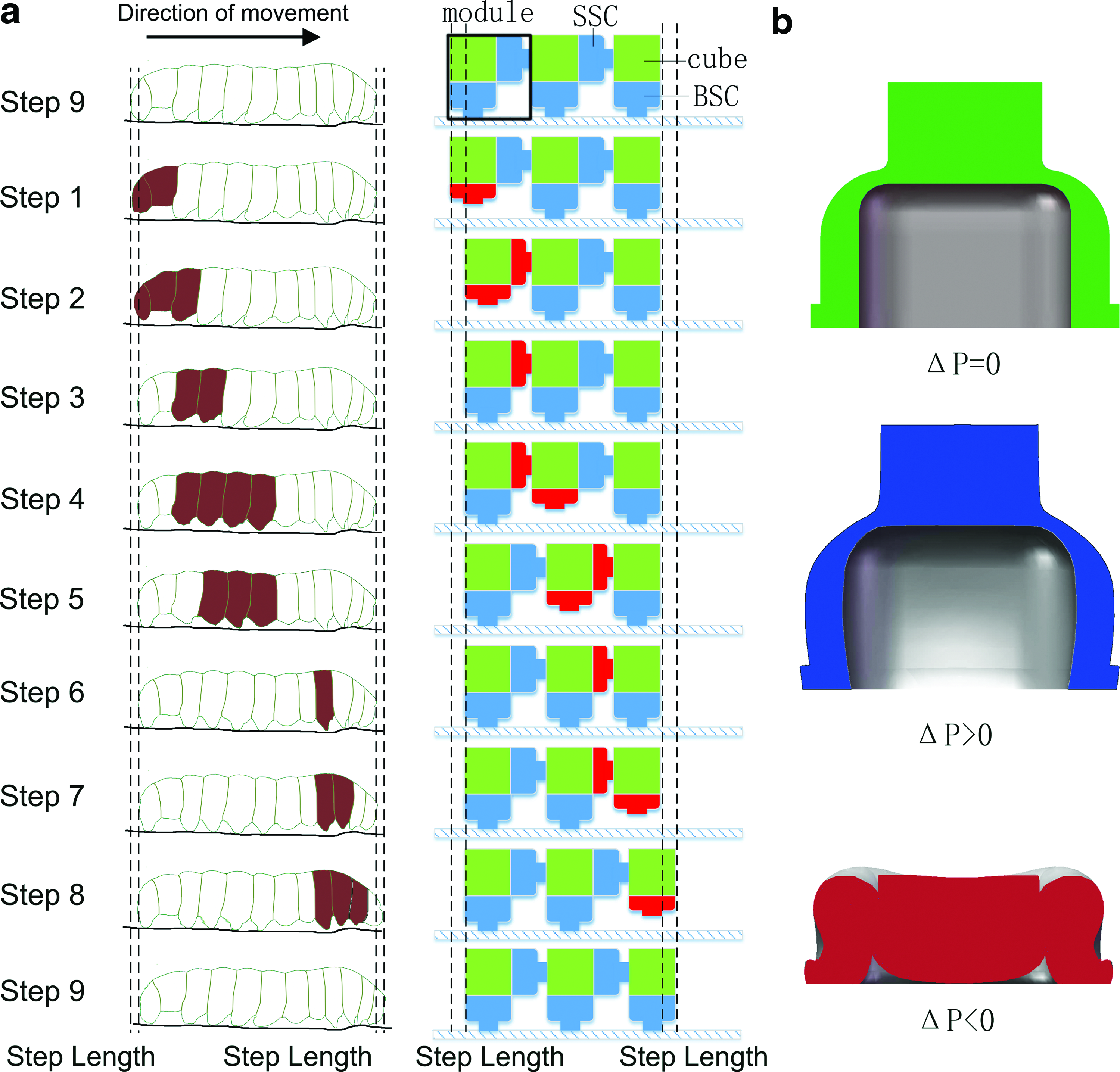
A preliminary model consisting of three modules is designed to mimic the crawling gait of the caterpillar (Fig. 1a). The modules of the robot are inspired by the segments of the caterpillar and the control of the modules is inspired by the movement of segments. Each leg of the caterpillar goes through two phases during each crawl, the swing phase during which the leg is lifted and moved forward, and the stance phase during which the leg is in contact with the ground or substrate. 23 During each cycle, all the three modules of the robot are also lifted, moved forward, and contacted with the ground as the crawling gait of the caterpillar. Each module is built by two different parts, the cubes served as the structure part and the soft cylinders fixed to the sides (named as SSC) and bottom (named as BSC) of the cubes served as actuators. The SSCs and the BSCs are in the same shape and are actuated pneumatically. Each soft cylinder is connected to a solenoid valve through a separate silicone tube. By controlling the solenoid valve, the soft cylinder contracts under a negative pressure and restores under a positive pressure (Fig. 1b). By contracting and restoring, the BSCs simulate the actions of the legs and the SSCs simulate the forward movement of the body.
The crawling gait can be achieved by three modules acting from rear to front. The progress of each module can be divided into three actions: (1) BSC contracts to remove the contact point from the ground, (2) SSC drives the forward movement, and (3) BSC restores and anchors to a new contact point with the ground.
Omnidirectional crawling gait of the soft robot
To achieve the motions with three DOFs, the robot has to produce propagating waves in two orthogonal directions for a two-dimensional translational motion, and two waves in opposite directions for the rotation. Therefore, we expend the preliminary model from a 1 × 3 rank to a 3 × 3 array (Fig. 2a). In this case, the traveling wave is propagated not only back and forward but also along the left and right. The robot can reach an arbitrary point on a plane in any angle. Two gaits of advancing and rotation are shown in Figure 2b and c, which follow the actuation timing in Figure 2f. Groups 6 and 7 in Figure 2f should be ignored for the gait of advancing. The nine steps of advancing and rotation are tabulated in Table 1.

The number of each group for advancing, rotating, and pipe crawling is shown in the first picture of Figure 2b, c and e.
BSC, soft cylinders fixed to the bottom; SSC, soft cylinders fixed to the sides.
A pipe-crawling form
By removing column 1 and column 3 of the omnidirectional soft robot, the movement of the robot in the pipe can be achieved (Fig. 2d). This version of the robot can stably crawl in the pipe, and avoid tilting with the SSCs on the side. With more modules added, this robot can be connected to any length. Crawling gait of the pipe-crawling form is shown in Figure 2e. The crawling cycle also consists of nine steps, following the actuation timing presented in Figure 2f. Groups 6 and 7 shown in Figure 2f should be ignored for the gait of pipe crawling. The nine steps of pipe-crawling gait are tabulated in Table 1.
Design and Fabrication of Modules
Material selection of the soft parts
The soft cylinders, the cubes, and the support chips are fabricated using the mold and casting approach. The molds required are made of ABS thermoplastics using a three-dimensional printer (Makerbot replicator Z18) with a resolution of 0.1 mm. We use a silicone with higher elastic modulus (Dragon skin 30; Smooth-On) to build the cubes and the support chips, and an extremely soft silicone (Ecoflex 00-30; Smooth-On) to build the soft cylinders. Since the material of the cubes has a much higher elastic modulus, the cubes basically keep still when the soft cylinders contract or expand.
Structure of one module
All the parts used to form a module are shown in Figure 3a. We have two kinds of soft cylinders, SSC and BSC. All the cylinders are of the same shape (top left and top right of Fig. 3a), but magnets are only embedded in SSC for assembly.

As shown in Figure 3b, each module has a hollow cube surrounded by soft walls with a thickness of 3 mm. There are five holes in the top surface and one hole in each of the other surfaces. Silicone pipes go through these holes from the top surface to other surfaces, connecting the soft cylinders with the valve. The number of the pipes is equal to the soft cylinders employed, dependent on the type of the module (Fig. 3c). Magnets are embedded inside the “free” surfaces without soft cylinders. The support chips are also glued to the “free” surfaces to prevent the modules from sagging.
Design of magnetic assembly
Round magnets with a diameter of 14 mm are embedded both in cubes and in the SSCs. With correct orientation of the magnetic pole, modules are capable of reassembly. When the SSC and free surface of different modules are close to each other, they will automatically connect (Fig. 3d). Neodymium-iron-boron (NdFeB) magnets are used to maximize the strength of connection with a limited mass, based on the high remanence per unit mass. 24
Experimental Design
The actuators are designed to switch between negative and positive pressure to perform a contraction–recovery cycle. We choose the working pressure for the soft robot according to the following criteria: (1) large displacement/flow ratio, (2) large displacement/energy cost ratio, and (3) sufficient output force. Several experiments are carried out to determine the properties of the soft cylinders, including the BSCs and SSCs.
The displacement–volume hysteresis curves and pressure–volume hysteresis curves
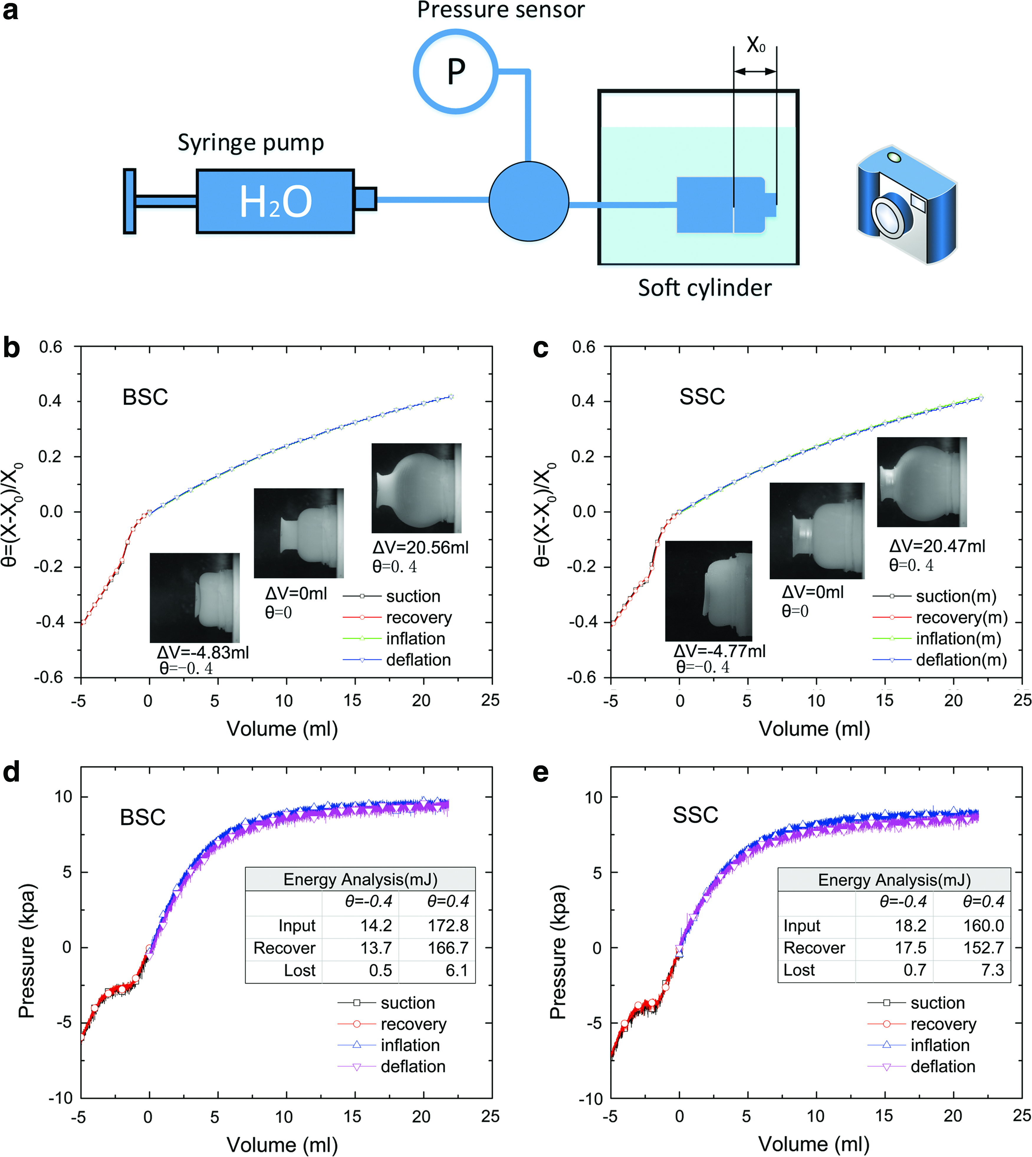
Displacement–volume (DV) hysteresis curves and pressure–volume (PV) hysteresis curves of the SSC and the BSC are observed in quasi-static measurements. To minimize the effect of gravity, one module is submerged in a glass tank filled with water. We squeeze the soft cylinders under water to remove all the air from the soft cylinders and the silicone tubes. A syringe pump, a pressure sensor, and the soft cylinder are then connected through a tee joint. A camera is placed perpendicular to the direction of motion. Since water is incompressible, we can measure the volume of water flowing in and out of the cylinder. We define a parameter θ as the strain where θ = (X-X0)/X0, where X is the length of the acting part of the cylinder and X0 is the original length. The measurement consists of four steps: (1) inflation, the soft cylinder is inflated from initial state to pressurized state by pumping water into it; (2) deflation, the soft cylinder is deflated from pressurized state until it returns to initial state; (3) contraction, the soft cylinder contracts from initial state by extraction of water; and (4) recovery, the soft cylinder recovers to initial state after contraction. The pressure and displacement during the four steps are recorded by the pressure sensor and the camera (Fig. 4a). The DV hysteresis curves and PV hysteresis curves of SSC and BSC are shown is Figure 4b–e.
The force–displacement hysteresis curves
Since the BSCs shall support the weight of the load and the SSCs shall overcome the resistance during recovery, we measure the force–displacement (FD) hysteresis curves of the soft cylinders at a pressurized condition in a process of inflation and squeezing.
The experimental setup is shown in Figure 5a. The module is fixed on a sliding board, with a dynamometer placed in the end of the screw rod. The soft cylinder is connected to a pressure control system whose inner pressure is controlled by a feedback system during the experiments.
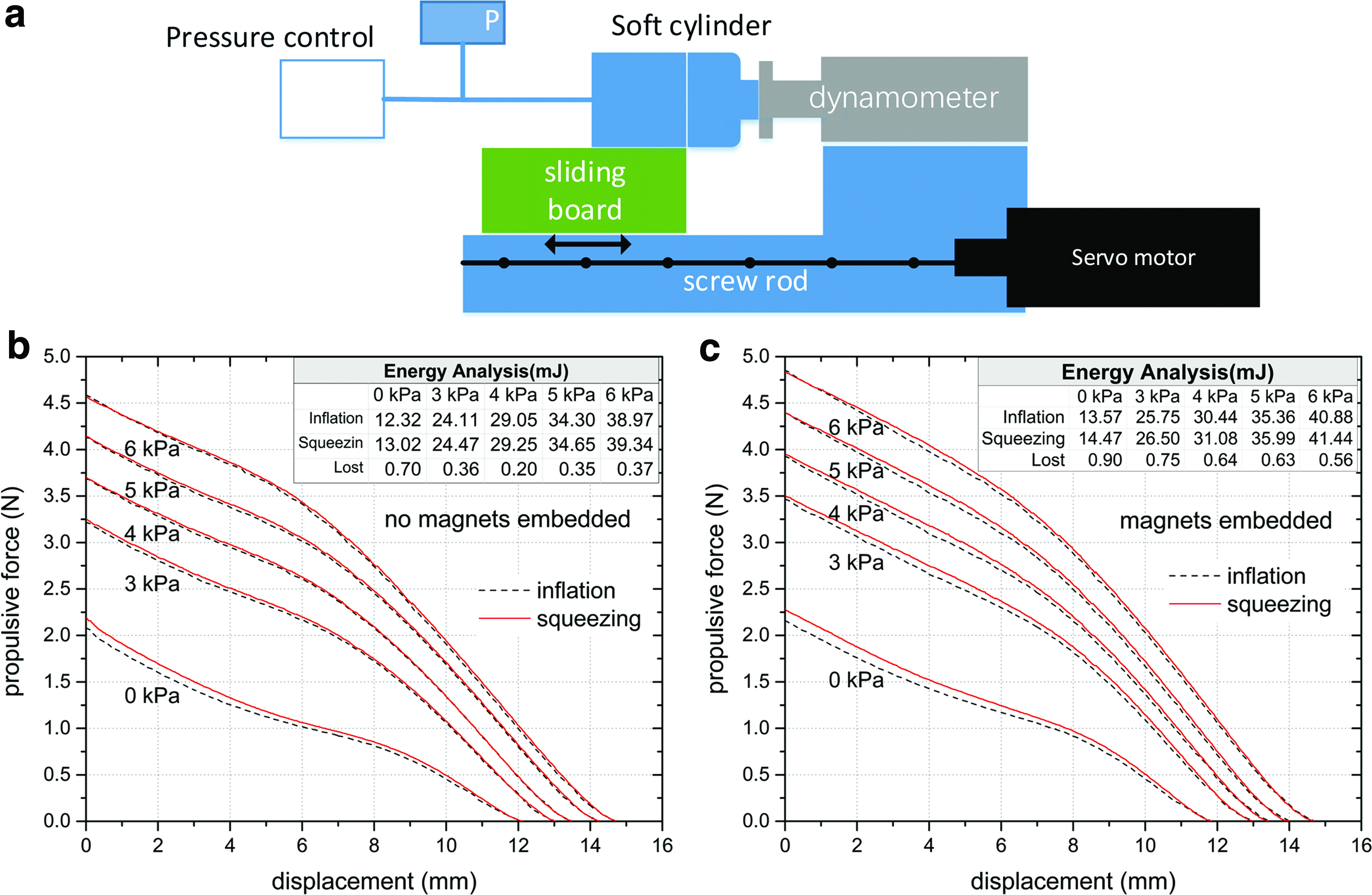
The soft cylinders are connected to a negative pressure at about −20 kPa to reach their maximum contraction before the tests, and this displacement is set as the start position. We then start the servo motor so that the soft cylinder approaches the dynamometer under the premise of zero contact pressure. The inner pressure of the soft cylinder is then changed to different positive pressures, so the soft cylinder applies a force to the dynamometer. Measurement of force starts from the maximum contraction to the maximum elongation (inflation) and return to the start point again (squeezing) at a speed of about 6 mm/min. The FD hysteresis curves produced by the BSC and the SSC under different positive pressures are shown in Figure 5b and c.
Results
Determining the working pressure for the soft cylinders
All the soft cylinders of the soft robot are driven by a vacuum source and a pressure gas source to simplify the design. The positive pressure is chosen to be about 5 kPa for the following reasons: (1) in the process of inflation and deflation, the DV hysteresis curves become more flat as the volume of fluid increases, which means the volume of fluid required to produce a unit of displacement is increasing (Fig. 4b, c). From the PV hysteresis curves, it is observed that the slope is dramatically decreasing after 5 kPa, which means it consumes much more volume of fluid to produce a unit of pressure (Fig. 4d, e). The internal volume of the soft cylinder only increases about 3 mL at 5 kPa, which means the consumption of flow is acceptable. (2) The contraction process can produce a deformation of θ = −0.4 by extracting around 5 mL of liquid, while an elongation of θ = 0.4 consumes about 20 mL of liquid. The PV hysteresis curves indicate that the energy required to produce a positive elongation of θ = 0.4 for both SSC and BSC is about 10 times larger than the contraction process of θ = −0.4. Since the progressive displacement is more energy dissipated relative to the negative displacement, the pressure of 5 kPa is low enough to avoid too much energy consumption. (3) The weight of a module ranges from about 50 g to about 90 g, which depends on the type of the modules, and the pressure of 5 kPa is sufficient for the BSC to support its own weight and for SSC to overcome the resistance during recovery (Fig. 5b, c).
Vacuum degree of 10 kPa is enough to achieve the action of the robot. However, using a lower pressure can accelerate the contraction process. In the latter tests, we use a vacuum degree of 20 kPa to drive the robot.
Controls for crawling gaits
Crawling in one direction
The omnidirectional soft robot crawling in one direction on a plane is shown in Figure 6. The crawling gait based on caterpillars is implemented by actions of the soft cylinders to create a traveling wave from the rear toward the front. The traveling wave results in a forward motion with a velocity of 18.5 m/h. (Supplementary Movies S1 and S2; Supplementary Data are available online at www.liebertpub.com/soro).

Rotation
If the modules are actuated in a rotation cycle as shown in Figure 2c, the modules on both sides will move in the opposite direction, thus driving the robot to rotate.
In our test, the first and third columns of the robot produce opposite traveling waves, then the first and third rows produce traveling waves in the opposite direction. All soft cylinders are actuated in this way, to eliminate the distortion caused by the twist. In the test, the robot rotates with an angular velocity of 1.63°/s with a standard deviation of ±0.19°/s or 2.09 ± 0.25°/gait cycle. However, the center is offset about 2.5 cm during the rotation of ∼180° (Fig. 7 and Supplementary Movie S3).

Crawling in a pipe
By removing the two side columns, the omnidirectional robot deforms into a pipe-crawling form, which is capable of crawling in a pipe with an inner diameter of 80 mm (Fig. 8 and Supplementary Movie S4). It is still actuated following the crawling gait we presented. Because of the adaptability of the soft cylinders and the flexibility of the material, the robot can work in pipes whose inner diameter varies from 75 to 85 mm.

Automatic combination of two robots
Two omnidirectional robots using different modules are capable of automatic combination (Fig. 9 and Supplementary Movie S5). One of the 3 × 3 matrix is modified by using three different modules so that it has three SSCs on one side to enable the combination. After the two 3 × 3 configurations are combined into a 3 × 6 configuration, the merged robot still moves with the omnidirectional crawling gait.

Discussion
We designed a pneumatically powered, reconfigurable omnidirectional soft robot. The robot is capable of movement in X and Y coordinates and rotation. The working pressure of the soft cylinder is determined from several experiments to confirm the properties of the soft cylinder.
The modules can be reconfigured into different task-based forms. These functions can also be achieved by hard robots, for example, using a hard cylinder to replace the soft cylinder. For hard robots, it might be very complicated to perform the highly precise synchronous motion, but the flexible structure can easily deal with the problem. In this work, the matching of two 3 × 3 configurations is easily completed without precise control (Supplementary Movie S4). The disadvantage is that the accuracy of motion is limited, such as the offset during the rotation process (Fig. 7 and Supplementary Movie S2) and the crawling in one direction (Supplementary Movie S1).
Conclusion
We propose a reconfigurable omnidirectional soft robot based on the locomotion of caterpillars. This pneumatically driven soft robot is capable of moving with three DOFs on a plane and being assembled into different task-based forms. Omnidirectional movement and reconfigurable features are important in exploring unstructured environments for soft mobile robots.
The design presented here has the following limitations: (1) it is still tethered, and this limits the use of the robot; (2) modules cannot automatically disconnect; (3) it lacks directional feedback control, and large deflections may arise during long-distance motion; and (4) no information is exchanged between the modules. One possible improvement is to install the pumps, controllers, electromagnets, and sensors into the cubes. Although embedding more components is difficult for the current modules, this approach shall be possible by optimizing the design and the materials in future.
Footnotes
Acknowledgments
This work is supported by the National Natural Science Foundation (No. 51475415 and No. 51521064) and Zhejiang Provincial Natural Science Foundation for Distinguished Young Scholars (No. LR15E050001).
Author Disclosure Statement
No competing financial interests exist.
References
Supplementary Material
Please find the following supplemental material available below.
For Open Access articles published under a Creative Commons License, all supplemental material carries the same license as the article it is associated with.
For non-Open Access articles published, all supplemental material carries a non-exclusive license, and permission requests for re-use of supplemental material or any part of supplemental material shall be sent directly to the copyright owner as specified in the copyright notice associated with the article.