
Abstract
Abstract
Molded silicone rubbers are common in manufacturing of soft robotic parts, but they are often prone to tears, punctures, and tensile failures when strained. In this article, we present a fabric compositing method for improving the mechanical properties of soft robotic parts by creating a fabric/rubber composite that increases the strength and durability of the molded rubber. Comprehensive ASTM material tests evaluating the strength, tear resistance, and puncture resistance are conducted on multiple composites embedded with different fabrics, including polyester, nylon, silk, cotton, rayon, and several blended fabrics. Results show that strong fabrics increase the strength and durability of the composite, valuable in pneumatic soft robotic applications, while elastic fabrics maintain elasticity and enhance tear strength, suitable for robotic skins or soft strain sensors. Two case studies then validate the proposed benefits of the fabric compositing for soft robotic pressure vessel applications and soft strain sensor applications. Evaluations of the fabric/rubber composite samples and devices indicate that such methods are effective for improving mechanical properties of soft robotic parts, resulting in parts that can have customized stiffness, strength, and vastly improved durability.
Introduction
E
Durability of soft robotic structures is ultimately limited by the fact that unreinforced elastomers provide poor tear resistance, especially once a tear has started. Despite this, unreinforced elastomers usually have low elastic modulus, allowing significant uni- and biaxial stretch. While strains are high in these conditions, stresses are low when failure occurs, which indicates limited load capacity. These factors limit practical robotic applications, such as skins, end effectors, and wearable devices, since these soft and weak materials cannot endure the forces or pressures typical of the device itself or from snagging or bumping objects in the environment.
Thus, while elastomers are easy to use, many robotic devices that use them share potential weaknesses in strength and durability, which could be addressed by this research. Like humans, robots manipulating objects and working in real-world environments will be damaged. For example, instrumented robotic hands2,3 and tactile fingertips 1 mounted on those hands are designed for robots to sense and manipulate real-world objects. Like humans, they are bound to suffer from cuts and abrasions and will eventually rip and fail under load. Similarly, soft strain sensors or robotic skins4,5 “feel” physical interactions through deformations of the soft substrate in which miniature sensors are embedded. As this research shows, however, unreinforced elastomers, typical of these and many other applications, are weak and prone to failure when punctured and stretched, which this research addresses.
In this article, we investigate a method of strengthening molded RTV silicone rubber parts through fabric compositing. The RTV silicone rubber materials used in this work, including Mold Max 40 (MM) and Ecoflex 000-35 (EF), are commercial products made by Smooth-On, Inc., which have 24-h and 2-h cure time, respectively, at room temperature. Other similar RTV elastomers usually require from less than an hour to a full day at room temperature to cure, although cure time could vary with specific materials selected and special catalysts used. A multistep molding process is developed to embed fabric in RTV silicone rubber to form the rubber/fabric composite. Six fabrics consisting of natural, synthetic, and blended fibers are examined for their potential to provide varying levels of strength and elastic modulus. The fabrics include polyester, nylon, polyester/cotton blend, rayon/spandex blend, silk, and cotton. A series of ASTM standard material tests are conducted on rubber specimens with and without fabric reinforcement to evaluate their tensile strength, tear resistance, and puncture resistance. Results from these tests are then used to identify parameters of mechanic models to predict composite behaviors. Case studies of two soft robotic applications are then presented. The first is a reinforced pneumatic bladder in the Smart Shoe, 11 demonstrating the application of fabric compositing in an elastomeric pressure vessel with complex geometry where stiffness, flexibility, and structural support are important. The second case study is of a reinforced strain sensor, 5 highlighting the capability of stretchable fabric to make sensors more resistant to puncture and tear, hence improving the potential of soft compliant skin for robots. Both case studies demonstrate that fabric compositing improves strength, functionality, and resistance to damage.
Reinforced elastomeric structures have been investigated previously. The soft spatial manipulator by Marchese and Rus 7 uses different wall thicknesses to reinforce and control directional stiffness and resulting deflection caused by pressurized chambers. McKibben actuators 8 wrap an inextensible braided sleeve around an elastomeric membrane such that pressurization causes the braid to bulge, shortening the actuator. The braid wears on the bladder, however, and can reduce life. Shan et al.13,14 developed a nonlinear, flexible, matrix composite membrane model for these actuators and further designed variable stiffness structures using a series of fluid-filled flexible matrix composite tubes. The actuator developed by Polygerinos et al. 9 uses a circumferential thread wrapped around the bladders to limit bulging while allowing the bladders to stretch axially and cause bending. This thins unreinforced rubber between the threads, which undermines durability. Composite reinforcement proposed in this article could address these issues by offering protection against thinning due to pressurization, wear, physical interactions, and aging of rubber material. This has been done to a limited degree with rubber seals by Yang et al., 15 but only one fabric is examined and only tensile strength was evaluated. This article examines additional fabrics suitable to different applications and also evaluates puncture and tear resistance. Ultimately, this article further validates the composite model from the work by Yang et al. 15 and includes additional characteristics.
This article makes several contributions. The main contributions of the article are the manufacturing process for embedding the fabric, experimental evaluations using different fabric/rubber composites, and derivation of an extended composite model and its material coefficients. Such validated models are valuable for researchers designing and applying these composites in soft robotics.
Hence, another contribution of this work is the finding that certain fabrics are better suited to improving mechanical properties of rubber structures, in particular soft robotic applications. As summarized in Table 1, based on the results presented later, composites with strong fabrics, such as polyester or nylon, enhance tensile strength, tear resistance, and puncture resistance, but strain is severely limited and sudden failure occurs at maximum strain. This could be valuable in pneumatic or hydraulic devices to limit rubber bulging and strengthen thin walls, thus stiffening the device for increased load capacity. Stretchable fabric composites, using materials such as rayon/spandex, Table 1, are demonstrated to maintain low elastic modulus across large deformations while enhancing tear and puncture resistance, but with sudden failure. Such materials are suitable for applications such as robotic skins, soft elastomeric sensors in instrumented fingers or hands, and soft fluidic actuators. Cotton composites, Table 1, support less load, but fail in multiple small failures, sequentially relieving stress, before catastrophic failure, which could again be useful for robotic skin.
Composites include Mold Max 40 + Polyester (MM + PLY), MM + Rayon/Spandex (MM + RS), MM + Cotton (MM + CT), and Ecoflex 000-35 + Rayon/Spandex (EF + RS). Typical unreinforced elastomers include silicone, MM, and EF used in this work, Polyurethane, natural rubber, and thermoplastic elastomers (TPE).
Letter and symbol representations: L–Low, M–Medium, H–High, N–No, Y–Yes, ▲–No Data.
When comparing to common elastomers,16–18 Table 1, these new silicone-based composite materials can offer superior material properties and can be configured into a wide range of elastic moduli and compliances, via different choices of embedded fabric and rubber materials, with enhanced tensile strength and good resistance to tear, puncture, and environmental factors, such as temperature, oils, acids, and alkalis. The weaknesses of unreinforced elastomers are obvious. Silicone rubber is known to be weak in tensile strength and can be torn or punctured to failure easily, but it is resistant to environmental factors, such as temperature, oil, acid, or alkali. Polyurethane rubber has higher elastic modulus and is stronger. However, its poor resistance to environmental changes (temperature, moisture, and acid) and poor elastic properties, including strong hysteresis, rate dependence, and softening stress/strain behavior under large strain, 19 greatly limit its applications for making response-critical soft robotic devices. Natural rubber and most TPE are cheaper for mass production, but require heated injection molding machines and possibly specific vulcanizing agents and procedures. Thus, they are more difficult to make in a laboratory environment than commercially available liquid silicone or polyurethane rubber that can be mixed and casted into almost any desired shape at room temperature. Besides, natural rubber and most TPE are prone to failure with exposure to extreme temperatures, oil, acid, or alkali.
Two soft robotic case studies, Figure 1, have then contributed to validate the hypothesized benefits of these material properties. The first focuses on a pneumatic bladder where different composites result in different compressive stiffnesses, ultimately leading to ideal composites for different applications. The second case study examines instrumented robotic skin, demonstrating significantly increased tear resistance and durability.

Fabric Characteristics
Fabric characteristics are key to the mechanical properties and durability of the fabric/rubber composites in soft robotic applications, where robotic parts are subject to cyclic loading and often lead to tearing and puncturing. Fabric improves strength while rubber allows elastic deformation and provides structural properties. Fabric characteristics such as strength and stretchability, as well as rubber permeability and absorbency, are highly dependent on fabric composition. Fabric is made with a complex process where fibers are first spun into yarns or threads and then woven together. Fiber composition, amount of fiber twist to make a yarn, number of yarns, amount of yarn twists to make a thread, weave density, and thread crimp all affect fabric characteristics. 20 Thus, the level of reinforcement achieved via fabric compositing varies greatly with fabric characteristics discussed below.
In this article, six common fabrics, including polyester, silk, nylon, 65%-polyester/35%-cotton blend, cotton, and 95%- rayon/5%-spandex blend, are evaluated and used to make fabric/rubber composites, Table 2.
Fabric strength
Fabric is usually composed of two sets of orthogonal yarns, passing over and under one another to make a patterned network of threads. These threads provide strength to the fabric by resisting tension along two fiber directions, often called warp and fill directions. Thus, the strength of a fabric sample along a weave direction is the sum of the strength of all threads in that loading direction. In this article, to quantify the fabric strength, the breaking strength of a fabric and its ultimate elongation are found by stretching a set of three specimens (25 mm wide, 150 mm long) on an Instron® (Illinois Tool Works, Inc.) test machine and averaging the values among all three specimens following the ASTM test standard D5053. 21 Furthermore, denier, 22 defined as the linear mass density of a fiber or a thread, is estimated by weighing a unit area (0.305 m by 0.305 m) fabric and calculating the mass per unit length, [mg/m], per thread. Tenacity, 22 known as the textile strength or the strength of a unit linear density thread, [N-m/g], is defined by the division of the breaking strength of each thread over the denier and is calculated for all six fabrics.
The test results, in Table 2, show both fabric strength per specimen and textile strength per denier for all six fabrics used in this article, sorted by breaking strength. Polyester fabric consists of high-density polyester fibers and is the strongest fabric and second strongest per tenacity. It can elongate to 40% of its original length before breaking. Silk is the second strongest fabric, but natural silk fiber has the highest tenacity due to its ultralow denier, indicating that silk fibers are the strongest per unit linear density. Or, in other words, silk fibers are the lightest per unit strength. However, silk fabric is the least stretchable with only ∼14% ultimate elongation. Nylon is as stretchable as polyester and relatively strong as well, but it is lighter than polyester in terms of linear density or denier. Cotton fiber and the fabric made of cotton are weak. However, when blended with stronger polyester fibers, polyester/cotton blend fabric becomes 63.7% stronger than cotton fabric, but it breaks at a similar level of 20% elongation. Strength of the polyester/cotton blended fiber and fabric is improved when compared with cotton. Rayon/spandex blend fabric is very weak in terms of strength and tenacity even though it has the highest fiber density among all six fabrics. However, rayon/spandex fibers demonstrate elastic behavior across ultrahigh deformations. Thus, polyester is 5.8 × stronger than rayon/spandex, but the latter has 4.8 × higher elongation at break.
These results suggest that certain fabrics are better suited to particular applications. Strong fabrics, such as polyester and silk, are suited to supporting high loads, such as strengthening a bladder. In contrast, elastic fabric, such as rayon/spandex, is suited to providing support in applications requiring low elastic modulus, such as in a strain sensor. Directional actuators may require a combination of materials to provide rigidity in one direction and compliance in another. This is discussed further in the section of composite material experimental results.
Permeability and absorbency
Permeability and absorbency of the fabric provide bonding with the rubber. Liquid permeability of a fabric allows liquid rubber to penetrate the fabric between the weaves. This forms connections and constraints between the rubber layers, encapsulating the fabric layer, and provides major bonding to hold the composite together. However, liquid permeability of fabric is not easy to measure and is dependent on the viscosity of the liquid rubber. In this article, permeability is characterized qualitatively as “high,” “median,” or “low” through visual inspection of thread spacing via a microscope, Figure 2a–f and shown in Table 2. Tight weaves with low permeability, such as polyester and silk, Figure 2a and b, make it difficult for liquid rubber to penetrate the fabric. The result is more of a “sandwich” structure where the layers could delaminate at failure. However, fabrics with slightly loose weaves, such as cotton, Figure 2e, and the blended materials, Figure 2d and f, allow higher permeability and provide improved adhesion by establishing physical connections between the rubber layers through the weaves.
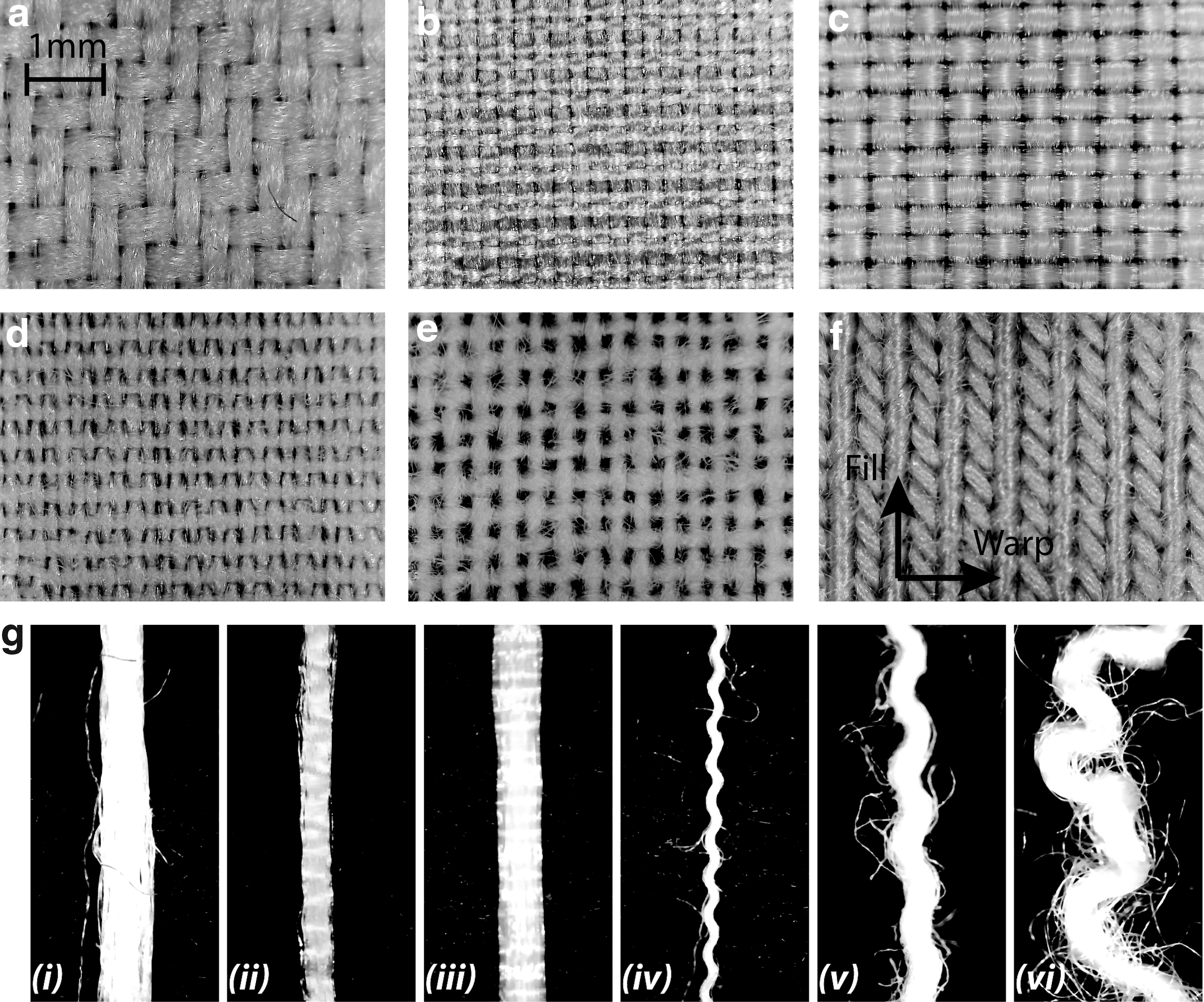
Microscopic view of six fabrics and their threads on a black background.
Absorbency23–26 of the fabric threads also contributes to bonding strength by absorbing liquid rubber into the thread. Thread irregularity and roughness help establish interactions between fibers in individual threads and the liquid rubber, thus creating improved bonding strength. Threads made of synthetic fibers, such as polyester, nylon, and silk, Figure 2g i–iii, are usually very smooth, thus lacking such interactions and have low absorbency. Cotton thread is rougher due to short and irregular cotton fibers, Figure 2g v, and thus has higher liquid rubber absorbency. A fabric blended with synthetic and natural fibers (e.g., 65% polyester, 35% cotton, Figure 2g iv) enjoys the high strength of polyester and the high absorbency of cotton fibers. Rayon, which is an artificial fabric, has high absorbency because of the irregularities in its thread construction, 26 Figure 2g vi. A corresponding qualitative measure of fabric absorbency is then presented in Table 2 based on the discussion above.
Flat Composite Manufacturing
Manufacturing flat fabric/rubber composites, typical of test specimens, robotic skin, and smart insoles, is more straight forward and is discussed first. Although the layup method has been widely used to manufacture many rigid composites, such as fiber/glass and carbon fiber composites, applying such a method with liquid rubber is relatively new and challenging. Manufacturing details and proposed procedures are presented below to provide guidance for soft robotic applications.
This section discusses manufacturing procedures for flat fabric/rubber composites using the hand layup method. Embedding fabric is challenging due to the high viscosity of the uncured silicone rubber, which makes it difficult to manipulate the fabric without permanently entrapping air bubbles. Therefore, proper manufacturing process design and handling of the embedded fabric during manufacturing are critical to forming a strong composite. Otherwise, the fabric may trap air bubbles, not laminate properly, and ultimately fail when loaded. Special processing as described below is required since fabric can easily trap bubbles.
Composite materials are added layer by layer in a flat level open mold. The bottom layer of rubber must be manufactured first, forming a substrate for subsequent layers. Liquid rubber is first mixed and then degassed in a vacuum to eliminate bubbles inadvertently formed during mixing. In this article, a sufficient amount of liquid rubber is poured in the mold and allowed to self-level to form the desired thickness of the bottom layer.
The fabric layer is then laid up by hand onto the substrate as follows. Fabric must first be cut into the desired shape and prepared by flattening and coating with rubber. Ironing is usually required to eliminate wrinkles in the fabric. Wrinkles naturally trap air and cause the fabric layer to become uneven. Ironing assures that the fabric is smooth and flat to conform with the flat substrate. Stiffening agents, such as starch, are not recommended since they affect absorbency of the threads and permeability of the fabric. Flattened fabric is then coated and wetted thoroughly by pouring a small amount of liquid rubber over it, which is then worked in with small spatula and excess material is removed. Wetted fabric allows the spaces between the threads to fill with rubber and allows the rubber to be absorbed by the threads, both of which promote bonding and help limit bubbles. While uncoated fabric can be easier to manipulate and may still bond with liquid substrate, it has difficulty absorbing rubber and is more likely to form air bubbles, and is thus not recommended.
The wetted fabric is laid onto the leveled substrate evenly across the width of the contact area, proceeding from one end of the mold gradually toward the other, Figure 3a. Ideally, this process is done when the substrate is still in a liquid or semicured state, which helps prevent bubbles and allows maximum bonding strength after curing. In the case of a fully cured substrate, which may be necessary for embedding components, sufficiently wetted fabric could still be applied if the bonding surface on the cured rubber is free of contaminants (e.g., dust, oil, and moisture). Contamination could be removed by wiping with high-purity isopropyl alcohol, pure acetone, or both sequentially.

Air bubbles must be removed after laying the fabric on the substrate. Gently working bubbles to the edges of the fabric and allowing to escape are recommended. Minimum force must be applied to avoid compressing uncured substrate since excessive force deforms the substrate and causes it to become uneven, possibly forcing material out of the mold. Applying vacuum is less effective and possibly counterproductive, and is not recommended to remove bubbles under the fabric. Wetted fabric acts like an impenetrable membrane and makes it almost impossible for bubbles to pass through the fabric. Instead, applying vacuum causes bubbles to naturally expand and coalesce, which causes larger scale debonding. As a result, vacuum cannot effectively evacuate air bubbles from under the fabric and is not recommended.
Another layer of rubber is then poured over the fabric layer to complete a three-layer fabric/rubber composite. It is worth noticing that rubber used to mold this top layer is required to be degassed after mixing and before pouring. Therefore, the degassed rubber, forming the top layer, can merge with the wetted fabric without forming air bubbles. This process can be repeated if multiple fabric layers are needed. In general, it is important that rubber work time, including mixing, degassing, and molding time, is strictly controlled within its pot life, leaving sufficient time to allow self-leveling and bubble removal during manufacturing of each layer.
The thicknesses of the rubber layers above and beneath the fabric may be varied, allowing the fabric to be molded in a desired plane within the composite structure. Strain would be limited in the plane where fabric is embedded due to the limited stretchability of the fabric, like the concept of a principal axis in mechanics. Rubber layers remain elastic, however. Thus, stiffness variations due to differences in rubber thickness on the two sides of the fabric would result in different mechanical behaviors as the composite bends in different directions. For example, thin rubber on one side and thick rubber on the other side of the fabric would allow larger bendability toward the thinner rubber side, Figure 3b, whereas molding the fabric in the middle plane would result in equivalent stiffness on either side.
Curved Composite Manufacturing
This section discusses manufacturing challenges and presents a general, step-by-step fabric compositing procedure for curved structures. The manufacturing process of a composite bladder is provided as an example in detail, but it could potentially be modified as well to fit other soft robotic applications, such as McKibben actuators 8 and soft spatial actuators.7,9
Manufacturing curved composite structures is significantly more difficult due to increased complexity in geometry and procedure. Similarly, composite materials are manufactured layer by layer. However, because every curved layer has a slightly different curvature or thickness, different molds with appropriate dimensions for each layer are required to construct each curved layer on the previous layer. Moreover, embedding the fabric layer is especially difficult since it is difficult for the embedded fabric to stay in place during molding. Thus, special design and processing are required to make high-quality composites.
Flexible mold construction
First, a more complex mold, as opposed to a simple flat mold used in manufacturing the flat composite, is required to shape the curved structure. Recently, 3D printing7,9,10 has been widely used in making such molds to construct delicate structures. However, the number of 3D-printed parts to make the mold increases quickly as the molding geometry becomes more complex since easy demolding is required to avoid breaking the delicate structures. Assembling and disassembling the mold then become more difficult. Wang and Minor 11 presented a method combining 3D printing and liquid rubber casting to make flexible rubber molds for casting a complex soft bladder network model with thin and fragile wall structures. Such a rubber mold is flexible, thus allowing low-stress demolding. It is recommended for applications with delicate structures, such as large membrane structures, that are fragile and prone to friction or resistance during demolding. In the bladder manufacturing process presented here, a flexible mold is adopted Wang and Minor 11 although a properly designed 3D-printed mold may also work.
The flexible mold construction first starts with making a 3D-printed Positive Model, usually made of plastic or resin, that includes fine features of the curved structure, Figure 4a. A two-piece rubber mold, Figure 4b, is then constructed in two steps by casting liquid rubber on two sides of the Positive Model. The two pieces of the mold should be designed and constructed to be easily assembled and disassembled as required by the multistep layup manufacturing procedure. For example, the Mold Base, Figure 4b–i, is first molded to the opening of the bowl-shaped bladder top surface.

Composite bladder manufacturing. Inner surface fabric placement:
The Mold Insert is then manufactured by pouring rubber into the assembly of the Positive Model and the rubber Mold Base. Appropriate release agents must be applied on both the inside and outside of the Positive Model and the first piece of rubber mold to allow easy separation and avoid damaging the rubber mold during demolding. Release agent should also be applied to the Mold Insert to allow demolding at the end of the process.
Substrate construction
Fabric can be embedded in different planes in the composite structure: near the inner surface, in the midplane, or near the outer surface. Each requires different processes and molds. In the case of embedding fabric near the inner surface, the wetted fabric could become the substrate layer by wrapping it directly over the Mold Insert, Figure 4c. Rubber material attached to the fabric would form a thin layer in between the fabric and the Mold Insert, although details of the fabric embedding process are presented in the following subsections.
In the cases of embedding the fabric layer in the midplane or near the outer surface, a rubber layer needs to be molded over the Mold Insert, which then forms the substrate for the fabric layer to be molded onto. A two-piece 3D-printed Substrate Mold, Figure 4c'-i, is specifically designed to form the rubber substrate layer. Again, 3D-printed molds require minimum cleaning since rubber does not bond to plastic or resin, and thus release agent can be avoided, allowing the substrate to form a better bonding surface. A flexible rubber Mold Base is not recommended since release agent would be needed, which contaminates bonding surfaces.
Fabric preparation
To prepare the fabric for embedding, it first needs to be cut to the proper shape and then wetted thoroughly with liquid rubber. Fabric dimensions should be based on the shape of the curved surface that it is going to be attached to. Here the fabric template is formed using the SolidWorks flattening tool applied to the slanted surface of the bladder. The surface is extended sufficiently to allow the material to wrap over the top of the bladder and to overlap the ends of the material when wrapped around the mold, enhancing strength. In the bladder manufacturing process, the template is then used to cut a piece of fan-shaped fabric, Figure 4c. The top and bottom of the bladder do not use fabric reinforcement since they interface with other components, but this is beyond the scope of this article. Rather, the key point in this application is to reinforce the sidewalls to improve pressure vessel properties of the bladder.
The fabric is then prepared with rubber similarly to the flat composite manufacturing in the previous section. The fabric is wetted thoroughly with rubber, which is worked in with spatula. Excess rubber is then removed.
Fabric wrapping
The wetted fabric is then applied to the Mold Insert, Figure 4c, or the substrate, Figure 4c'-ii, described previously using a manual layup procedure. One end of the wetted fabric is applied first and then gradually wrapped around the substrate to assure that air bubbles are not entrapped. Sufficient tension is necessary to assure complete contact of the cloth with the substrate, which squeezes out air bubbles in the process. Ultimately, the wetted fabric is wrapped completely around the substrate, resulting in the two ends of the fabric overlapping to form a joint in the cured part. Tension must be limited since viscous friction of the liquid rubber is generally used to hold the fabric in place. Likewise, excessive tension can squeeze out the liquid rubber and result in insufficient rubber for bonding.
Fabric overlapping
Fabric folding and overlapping are a necessary aspect of manufacturing with fabric composites over complex curved surfaces since it is impossible for a flat piece of fabric to uniformly cover the surface. Fabric folds must be formed properly to ensure strength and durability when fitting a piece of flat fabric onto a curved surface. Non-overlapped stand-up wrinkles, Figure 5a, are weak and easy to separate under tensile load, whereas overlapped folds, Figure 5c, have enhanced shear strength in the folded area provided by multiple layers of fabric. When loaded, strain concentration occurs in the areas where the reinforced fabric layer is discontinued, highlighted in yellow lines in Figure 5. Rubber delamination is more likely to happen in these regions as strain increases.

Illustrations of embedded fabric folds and strain concentrations.
In the case of a stand-up wrinkle, Figure 5a, the vertical fabric segments and the rubber in the middle are, primarily, in a tensile loading mode. Fabric reinforcement is missing in the loading direction at the bottom of the wrinkle. Small material separation, or fracture, caused by stress concentration, would continue to develop until the wrinkle is stretched and stress is evenly distributed along the fabric. In contrast, in the case of an overlapped wrinkle, Figure 5c, the horizontal fabric segments and the rubber around them are, primarily, in a shear loading mode. The embedded fabric is folded in the horizontal direction to cover the entire area and limit strain continuously along the loading direction, thus limiting potential fractures from propagating.
Simple finite element analysis (FEA) in Abaqus Standard (Dassault Systèmes) was carried out to demonstrate the fabric overlapping idea. The composite wrinkles were modeled as a 3D planar shell (10 × 2 mm, with a thickness of 20 mm; embedded fabric thickness is set to 0.1 mm), Figure 5b and d, in which Mold Max 40 material test data were applied to the hyperelastic rubber model and the fabric Young's modulus was set to 1 GPa in an isotropic elastic model. The composite behavior under tensile load was generally correct in that it showed that rubber elements between stiff fabric layers undergo large tensile and shear deformations. However, the isotropic fabric material model made the fabric layer hard to bend or stretch. As a result, the accuracy of this model might be affected and will need to be addressed by more sophisticated models in future work. Likewise, advanced FEA models would be able to estimate material delamination, but a more thorough study of the fabric/rubber interaction and microrupture is required in future work.
It was also discovered in previous experiments that a curved composite bladder wall with several equally spaced small folds, as shown in Figure 5a, was more prone to structural failure whereas a larger overlapped fold combining those small ones was stronger when fitting the same curved surface. Such a trend was also highlighted by FEA results, Figure 5e, that indicate that a stand-up wrinkle is much weaker than an overlapped wrinkle when the same amount of strain is applied. Thus, the overlapping folds are preferred over stand-up wrinkles for enhanced structural strength and reliability.
An extra layer of wetted fabric, which we call a “patch,” should be applied if weak areas are anticipated. For example, a patch should be applied if stand-up wrinkles are formed during manufacturing, especially where rubber is squeezed out from under the wrinkle. Likewise, a patch should be applied if there is insufficient overlap between two sections of fabric. Patches can also be applied if failure occurs, but careful surface preparation is required. In all of these cases, “patches” provide an extra layer of reinforcement and ensure reliability.
The size of the patch or overlapping fabric, Figure 6, should be large enough to provide shear resistance and limit potential failure caused by fracture propagation. It is related to the bonding strength between the fabric and the rubber substrate. Consider a unit area of a fabric, Figure 6b, the green region in plane with the fabric indicates rubber thread bonding area, which is directly related to the rubber absorbency of the thread. The black area indicates through-thickness permeation of liquid rubber and, thus, is bonded with rubber through the hole. Fabric composite bonding failure occurs when fabric starts to separate from the rubber substrate due to tensile strain,
where

As a result, for an overlapped fold, Figure 5b, or a joint, Figure 6a, to bear a load force F and its corresponding shear deformation
Therefore, it is recommended that the size of the fabric overlap discussed in this section and the previous subsection should be estimated and designed based on these rules.
Clamping
A two-piece 3D-printed clamp is designed to firmly encapsulate the folded fabric directly onto the surface of the Mold Insert, Figure 4c, or a rubber substrate, Figure 4c'-ii, depending on the location of the fabric layer in the composite. Note the clamps in Figure 4c and c'-ii have different internal dimensions due to the thickness variations of the substrate. The thickness of the wetted fabric and folds needs to be accounted for when designing the clamp to allow enough liquid rubber inside to serve as substrate or bonding agent. The clamp is then carefully assembled and pressed together firmly to encapsulate the wetted fabric with folds inside to cure. It is vital that the inner surface of the clamp is clean and not sprayed with release agent since the wetted fabric layer needs to be molded around with rubber again later.
Once the wetted fabric layer is cured, the clamp can be removed, leaving the hardened fabric closely adhered to the Mold Insert surface or rubber substrate. Extra caution must be taken to ensure that the surface of the cured fabric layer is not contaminated when removing the clamp. Wiping the surface with high-purity isopropyl alcohol and pure acetone sequentially is recommended to ensure bonding strength in the following step.
Outer layer molding
Before molding the outer rubber layer around the cured fabric layer, air bubbles formed on the surface of the cure fabric layer in the previous step need to be filled with liquid rubber. It is recommended to apply a thin layer of liquid rubber on the cured fabric layer to fill all bubbles as well as form a liquid surface that merges easily with liquid rubber in the mold later.
It is also important to note that air bubbles formed inside the closed mold are very difficult to evacuate. Unlike molding thin rubber sheets with a large open mold, removing air bubbles from closed molds, or molds with deep thin grooves, is challenging. Air bubbles are trapped by large viscous drag from liquid rubber with the solid mold closely around it. Moreover, the embedded fabric adds more friction and drag stops bubbles from moving. Worse, applying vacuum causes the bubbles to expand and pushes liquid rubber out of the mold. Bubbles trapped deep inside the mold most likely stay in place or even combine into bigger bubbles. Thus, proper coating and clamping processes discussed below are crucial to avoid air bubbles.
To mold the outer rubber layer, degassed liquid rubber is first poured into the Mold Base. A little extra rubber should be used to assure complete filling of the mold. The Mold Insert, with cured fabric layer closely attached to it, is then slowly set into the Mold Base, Figure 4d. A small pressing force applied to the top of the Mold Insert is suggested to slowly press the two-piece mold together. Thus, rubber coating on the fabric layer and the liquid rubber in the Mold Base could merge smoothly without forming bubbles. Excess material would be squeezed out as the two-piece mold closes.
A fabric-reinforced rubber composite bladder is finally built with the embedded fabric molded close to the inner surface, Figure 4e, through steps shown in Figure 4c. Likewise, the fabric can be embedded in the middle plane, Figure 4e', or near the outer surface through steps shown in Figure 4c'.
Fabric/Rubber Composite Model
The mechanical behaviors of the fabric/rubber composite can be predicted through mechanic models. Therefore, the design and properties of the soft robotic parts made through fabric compositing could be evaluated analytically.
In this section, the constitutive model from Yang et al. 15 is extended to capture complete uniaxial tensile responses for different fabric/rubber composites. Multiple hyperelastic models (e.g., Neo–Hooke, Mooney–Rivlin (M-R), Ogden, and Polynomial) were evaluated by fitting the tensile and compression test data for the MM silicone rubber. The M-R constitutive model is selected for the rubber material since it offers good characterization of the material behavior as indicated later in Figure 7h and Table 4. Likewise, the constitutive model from Yang et al. 15 combines the M-R hyperelastic rubber model and the fabric and rubber/fabric models, further demonstrating that the M-R model is effective in estimating fabric-reinforced rubber composite behavior. Since Yang et al. 15 provide limited results, this article extends their model to better describe composite behavior and provides validating results.

Engineering stress/strain curves of all seven materials:
For the fabric/rubber composite in this work, the total strain energy can be expressed as the sum of strain energy of the rubber substrate, WR, the strain energy of the embedded fabric, WF, and the interactions between rubber and fabric,
The strain energy of rubber, WR, is described by the Mooney–Rivlin hyperelastic model and can be written as follows:
where
The strain energy of the fabric and the fabric/rubber interaction are adopted from biotissue materials
27
and can be written as follows:
where k1 and k2 describe the property of the embedded fabric and the interaction between rubber and fabric, respectively.
Based on tensor analysis, the Cauchy stress tensor
where p is a Lagrange multiplier that associates with material incompressibility, and has a physical meaning to represent the hydrostatic pressure;
where
Moreover, the relationship between the nominal stress
Thus, the nominal stress
In the case of a uniaxial tensile test, the deformation mode can be characterized in terms of the principal stretches,
However, this stress/strain relationship does not capture the composite softening effect due to fiber microruptures,28,29 observed in our results with multiple fabric/rubber composites, presented later in experimental results and Figure 7. In this work, Equation (12) is extended by including an extra term,
After substituting nominal stretch
Hence, five material constants,
Experimental Evaluation
Understanding the mechanical properties of materials is critical to helping engineers design next-generation soft robotics. To quantify and evaluate mechanical properties of the fabric-reinforced rubber composites, three sets of tests, including tensile strength, tear resistance, and puncture resistance tests, were performed on an Instron test machine. The six fabrics characterized previously were used to construct composites with the Mold Max 40 silicone rubber (Smooth-On, Inc., cures in 24 h at room temperature). Unreinforced pure silicone rubber samples were used as the control group. Corresponding test methods and results are presented. Discussion of results at the end of the section highlights that particular composites are better for improving strength and rigidity, maintaining elasticity with large deflections, and providing durability, which are important considerations for soft robotic skins, actuators, fingers, and so on.
Tensile strength
The tensile strength test evaluates stress/strain relationships when the composite is under uniaxial tensile load. Tensile tests highlight that some composites greatly improve strength, while others demonstrate elastic behaviors under large deformations.
Sample preparation and test apparatus
Testing was performed following the ASTM D412 test standard. 30 A flat sheet of silicone/fabric composite was first made with a uniform thickness of 2 ± 0.2 mm using the technique described in the Flat Composite Manufacturing section. Dumbbell-shaped specimens were then cut. Dimensions, including thickness, width, and length, of each specimen were measured and recorded before testing for quality control and stress and strain calculations after testing. Three specimens were tested for all six fabric composites as well as the unreinforced pure silicone rubber, which served as a control group. Extension and load data were recorded on the control computer.
Tensile strength, ultimate elongation, modulus, and toughness
Figure 7 shows engineering stress/strain relationships of all composite and unreinforced rubber tensile tests with three samples per material. Rayon/spandex were tested in both fill and warp directions due to the differences in fabric construction, Figure 2f. Figure 8 plots the average engineering stresses of three specimens in a group and their standard deviations in shaded colors, where the differences in material modulus (e.g., stiffness) are clearly highlighted by the slope of the stress/strain curves.

Average stresses (solid lines) and standard deviations (shaded boundaries) of all seven types of materials (six composites and an unreinforced rubber) in uniaxial tensile tests. Average stresses are plotted to the lowest strains among three specimens in each group.
During the tensile tests, it was noticed that several groups of composites had multistage failures before the dumbbell specimens came to a catastrophic failure, discussed later in the “Multistage failure mode” subsection. Therefore, multiple peaks could be seen in some stress/strain curves, Figure 7a, c, d, and g. In this article, tensile strength per composite was found as the average stresses of three specimens at their first rupture points, labeled with crosses in Figure 7. Average tensile strength of three specimens is reported in Table 2.
Tensile strength, characterized by maximum stress, is improved in most fabric composites. Percentage of reinforcement achieved in each composite compared to unreinforced pure silicone rubber is calculated and reported in Table 3. Key findings are highlighted: (1) four out of six composites are significantly stronger than unreinforced silicone rubber, polyester composite is the strongest at 3.86 × the unreinforced; (2) when comparing with pure fabric strength in Table 2, silk is the second strongest, however, the silk/rubber composite becomes weaker than nylon or polyester/cotton composites; (3) cotton and rayon/spandex composites are weaker than pure silicone rubber under tensile load. While the fabric/rubber composite strength is mainly contributed by the fabric strength, it is also highly dependent on fabric characteristics as well as rubber/fabric interaction.
Embedded fabric affects composite elastic modulus by limiting strain along two fiber directions. According to Table 2, only rayon/spandex fabric shows high stretchability (∼200% ultimate elongation), while other conventional fabrics are not as stretchable with 14.7–40.4% ultimate elongation. As a result, rayon/spandex composite elongates ∼120% before breaking and is highest among all composites, Table 3. It is much less than the elongation of rayon/spandex fabric or silicone rubber alone (both at ∼200%). Such a decrease in ultimate elongation is likely due to fabric/rubber interaction inside the composite that induces constraints and causes stress concentrations in its microstructures, although this hypothesis is subject to future investigations. Other fabric composites have similar levels of ultimate elongation as their embedded fabrics.
Composite modulus is represented by the slope of stress/strain profile, Figure 8. It indicates the composite structural stiffness and thus the ability to resist tension. Polyester, polyester/cotton blend, and silk composites have high modulus, ideal for stiff strain-limiting applications. Nylon and cotton composite moduli are median. Rayon/spandex composite shows almost identical stress/strain curves in two different fiber directions. It has the lowest modulus among all composites and requires the least load to stretch.
Softening effects are seen in multiple composites before they fail, such as silk and rayon/spandex composites. Such effect shows much earlier at ∼20% strain for rayon/spandex composite. The softening effect causes difficulties for the constitutive model by Yang et al., 15 which characterizes fabric and fabric/rubber interaction with an exponential-based term that cannot capture such an effect. These results justify the proposed model, Equation (14), which better describes the softening behavior.
Tensile toughness describes the energy capacitance or load capacity of a composite when plastically tensioned without fracturing. 31 Thus, toughness can be represented by the area under the stress/strain curve. Here, this property is estimated via the product of tensile strength and ultimate elongation, Table 3, which calculates the triangular area under the stress/strain curve. The unreinforced pure silicone rubber is toughest, whereas all fabric/rubber composites have reduced toughness. Polyester and nylon composites have similar toughness, while their strength and ultimate elongation are improved over unreinforced rubber. While rayon/spandex composite is lower in strength than unreinforced rubber, it is still reasonably tough. The rest of the composites have low toughness with cotton composite being the least tough at only ∼10% of the toughness of pure silicone.
Multistage failure mode
Multistage failure behaviors were seen in most composite specimens. Before complete tensile failure of the specimens, the embedded fabric layer broke at one to two spots, while the silicone rubber layers remained intact and elastic. Stress dropped to the level of 1–2 MPa consistently due to the limited strength of the silicone rubber supporting the load. With additional strain application, the composite layers were again loaded and stresses could increase.
Composites embedded with strong fabrics, including polyester, nylon, polyester/cotton blend, and silk, Figure 7a–d respectively, tend to have a large stress drop first, indicating an initial failure of the embedded fabric. A smaller stress drop follows due to failure of rubber layers at the same place. Some test data did not show such a two-stage failure behavior because the test machine did not continue to stretch the specimens to complete separations, and thus, such data were not recorded in all tests.
In comparison, most cotton fabric composite specimens broke at two spots before complete failure, Figure 7g. Smaller stress drops were seen due to the low strength of the cotton fabric. Fabric breaks at multiple locations would frequently occur incrementally due to the weakness of the cotton fabric compared to rubber. Thus, when the fabric would break at a location, the rubber would continue to stretch at that location until stresses in the fabric composite were sufficient to cause another failure at a different location. Ultimate failure occurred with continued strain application at one of these break locations, typically after the two fabric failures.
Multistage failure behavior was not observed in the rayon/spandex composites. This was because the rayon/spandex fabric was sufficiently elastic that it could elongate with the rubber substrate. It can be seen from Figure 7e and f and Table 3 that the rayon/spandex-reinforced rubber composites have large elongations, like the pure silicone rubber. Therefore, when the composite breaks at large strain (over 110%), sudden release of the load on either fabric or rubber would cause overload on the other, leading to catastrophic failure of the entire composite.
Constitutive model parameters
The averaged tensile stress/strain data of each composite material are fit to the constitutive model in Equation (14) and used to estimate the material coefficients, Table 4. The rayon/spandex composite has slight variations in material coefficients in the fill and warp directions. The model predicted uniaxial stress/strain relationships are then calculated and plotted in red dashed lines in Figure 7. The model matches experimental results well for all composites, verifying the proposed model from Equation (14) for predicting tensile behaviors of fabric-reinforced rubber composites. Such validated uniaxial models are useful for modeling and FEA, 11 which support design and analysis of soft robotic parts using fabric composites in future work.
Tear resistance
Tear strength is another vital criterion that determines the strength and durability of elastomers. Tears start with tiny fractures that can propagate quickly under load, resulting in failures that can be catastrophic. Results highlight that fabrics made of synthetic fibers significantly improve tear resistance.
Sample preparation and test apparatus
The tear strength test was conducted following the ASTM D624 test standard. 32 Type B tear test method was performed. As per the test standard, specimens were cut from a uniformly molded fabric-reinforced silicone rubber sheet with a desired overall thickness of 2.3 ± 1.0 mm. Fabric reinforcement was molded roughly in the middle plane of the composite sheet using the method presented previously. Tear strength was found via the division of the maximum force and the median thickness of each sample. Three specimens were tested for each material and results were averaged. The same grippers and test machine from tensile tests were used.
Test results
It can be seen from Table 3 that fabrics made of synthetic fibers, such as polyester, nylon, and rayon/spandex, significantly enhance the tear strength of the composites. The polyester composite has the highest tear strength at 564% of unreinforced rubber. Nylon and rayon/spandex composites have similar high tear strength at ∼350% of unreinforced rubber. In contrast, silk and cotton fabrics, made of natural fibers, only provide limited strengthening. The cotton fabric-reinforced silicone rubber is only 137% of unreinforced rubber, but the 65% polyester/35% cotton blended fabric composite has an intermediate tear strength of 262% of unreinforced rubber. Hence, the addition of polyester to cotton achieves nearly double the tear strength while also providing the excellent bonding and permeability of the cotton fabric.
Puncture resistance
Puncture resistance is important for robotic parts that frequently interact with the physical world and potential hazards, such as sharp corners or pointy needles.
Sample preparation and test apparatus
The puncture resistance test was performed with the guidance of the MIS-STD-3010 standard. A test specimen holding fixture and a puncturing probe, as per MIS standard, were manufactured and assembled on the same Instron test machine used in the prior tests. The specimen holding fixture consists of two metal plates to clamp a test specimen between them with 1-inch holes at their center to allow a probe to load the material. Sandpaper was used inside clamps to prevent slipping. The probe was formed from 0.5-inch-diameter steel rod machined to a 1/8-inch (3.2 mm) spherical radius at the tip with a 2-inch (50.8 mm)-long taper. Five pieces of 2-by-2 inch (50.8 × 50.8 mm2) specimens with thicknesses of 1.5 ± 0.2 mm were tested for the unreinforced rubber and all six composites. Again, the fabric was molded roughly in the midplane of the composites.
Test results
Like tensile strength and tear resistance test results, composites made with synthetic fabrics, for example, polyester, nylon, and polyester/cotton, demonstrated significant puncture resistance at 219–474% of pure rubber. Composites using embedded cotton and silk fabrics made from natural fibers demonstrated slight improvements at 117% and 140% of pure rubber. Rayon/spandex composites provided median reinforcement at 155% of pure silicone.
Discussion
It can be seen from the test results above that fabrics, such as polyester, nylon, and polyester/cotton, enhance tensile strength, tear strength, and puncture resistance at the same time. Thus, they are suitable for toughening structures and reducing strain in soft robotic applications, such as pressure vessels or pneumatic bladders. Rayon/spandex is highly stretchable and remains elastic, but weak in tensile strength. However, it is relatively tough and could resist large tear load, indicating its potential to reinforce elastic robotic parts, such as robotic skin sensors and soft bending actuators. Composites using synthetic fabrics or synthetic blends, for example, polyester/cotton, have significant enhancement of mechanical properties. On the contrary, composites using all natural fabrics, for example, cotton and silk fabrics, are relatively weak and thus not suitable for improving composite strength. It is noted, however, that the natural fabric composites are stiffer, which can be useful for improving stiffness of soft robotic parts. The lower strength and sequential failure of the cotton composites could suit them for providing gradual mechanical load relief.
Case Study I: Pneumatic Bladder
This section presents a case study of reinforced pneumatic bladders designed for the Smart Shoe. 11 The shoe physically renders the shape of terrain in a virtual reality environment using an array of controllable bladders in the shoe sole. This demonstrates the feasibility and benefit of applying the different fabric composites in pressure vessels. It also demonstrates the potential for applying fabric composites in soft robotic fluidic bending actuators.
Pneumatic bladder-based Smart Shoe background
The Smart Shoe 11 is a novel instrumented haptic footwear for rendering both gross and fine terrain features through a shoe sole using a controllable bladder array. Each bladder is instrumented individually with an embedded valve, pressure sensor, range finder, and microcontroller that control the bladder. Bladders are passively deflated when the valves are open and a user steps on the shoe. Control of bladder array deflation creates the sensation of stepping on terrain with different shapes and slopes. The compliant structure allows the bladders to reinflate if the valves are opened when the user lifts their foot during the swing phase of their gait.
While the original Smart Shoe 11 is capable of rendering terrain features that are not seen on other haptic devices, it has strength and durability issues that have led to the research of an improved bladder system. One major advancement is the proposed stand-alone bladders, Figures 1a and 9a, which will ultimately be combined to form a new bladder array in future work. These new pneumatic bladders were first made of pure silicone rubber, namely Mold Max 40. However, when compressed by the weight of the user, the closed unreinforced bladders bulged due to increased internal pressure.

Adding reinforcement provides significant benefit to the bladders. Reinforcement has potential to reduce bulging, which increases vertical stiffness of the inflated bladders when the valves are closed. This stiffness allows improved haptic display since stiffer bladders are easier to perceive and should be able to be controlled to better display a wider range of terrain impedance. Likewise, rendered terrain height and slope can be improved since the stiffer bladders deflect less when loaded, making the difference between an inflated and deflated bladder more significant. Most importantly, life and durability can be improved significantly by reinforcement since bladders undergo large displacements and extreme buckling.
Composite bladders
To select a desired composite to reinforce the Smart Shoe bladder, all six fabrics evaluated in the previous sections were utilized to make composite bladders using procedures a-b-c-d-e in Figure 4. All bladders were sealed by gluing to a rubber substrate using the Sil-Poxy silicone adhesive (Smooth-On, Inc., cures in 2 h at room temperature). Grinding and cleaning of the bonding surfaces were performed to ensure bonding strength.
On preliminary cyclic compression testing, material delamination was observed in polyester, nylon, and silk composite bladders due to limited fabric permeability and absorbency, Table 2, resulting in poor bonding strength between fabric and rubber layers. Although these fabric/rubber composites were strong as per tensile, tear, and puncture tests in the previous section, their smooth and tight weaves tended to repel liquid rubber and stop rubber from permeating through the weaves to establish bonding between layers. Such a weakness in bonding strength of these composite bladders is fatal under extreme cyclic buckling, limiting durability. On the contrary, the cotton composite bladder bonded well, but broke under large compression due to fabric and composite weakness indicated previously; Tables 2 and 3, respectively. Thus, these fabric composites are not suitable for constructing the Smart Shoe bladders, which require strong and durable materials.
Further testing of the bladders was limited to the remaining materials and was compared to an unreinforced bladder. The materials included the polyester/cotton composite bladder, which provides the strength and durability of polyester and the superior bonding of cotton. Tests also included the rayon/spandex composite bladder. Such composites are compliant like the unreinforced rubber, but with significantly increased durability. While such compliance may not be appropriate for the Smart Shoe, it can certainly be used in applications where compliance is important, such as in directional fluidic bending actuators used in soft robotics.
Bladder experimental evaluations
Uniaxial compression tests were implemented on the ankle foot simulator testbed,33,34 using only its vertical degree of freedom. A piece of flat aluminum plate was attached to the bottom of the ankle load cell to compress the bladder against an AMTI force plate, which measured the force in vertical direction. Bladders were compressed at 10 mm/s for 30 mm, held on for a second, and then released at the same speed. Bladders were first tested in the inflated state and then the deflated state by cutting small holes to let air evacuate during compression. The control computer measured compression displacement and force simultaneously using the force plate.
Bladder buckling, Figure 9a, varied due to different wall stiffnesses, Figure 9b and c. When inflated, the unreinforced bladder bulged under compression. The inflated rayon bladder bulged similarly since the embedded rayon/spandex fabric has low elastic modulus. Polyester/cotton bladder, on the contrary, buckled inward even with high internal air pressure, resulting in high stiffness and enhanced load capacity, Figure 9b. Such inward buckling behavior is similar to the deflated bladder behaviors, indicating that the polyester/cotton composite bladder wall is so stiff that bulging in nearly nonexistent, even with increased internal air pressure. Although these bladders are not instrumented and are not able to measure internal pressure, future prototypes will include electronics and sensors to allow full functionality of the bladders and Smart Shoe.
The bladder force-versus-compression plots, Figure 9b and c, indicate bladder vertical stiffness. When inflated, Figure 9b, the polyester/cotton bladder shows significantly higher stiffness over the other two after the initial compression. Rayon/spandex bladder bulges, Figure 9a. It is more compliant and is only a little stiffer than the unreinforced bladder. When deflated, Figure 9c, the polyester/cotton bladder is the stiffest, especially when nearly fully compressed. In contrast, the rayon/spandex bladder and the unreinforced bladder are both compliant and buckle relatively easy.
In summary, the polyester/cotton bladder is much stiffer and is the stiffest among all three bladders. Such enhanced structural stiffness is promising for making a better haptic Smart Shoe, as well as making rubber pressure vessels with enhanced load capacity. The rayon/spandex bladder is almost as compliant as the unreinforced bladder, but is much less prone to tear or puncture, Table 3. Such compliant reinforcement can be used to create durable soft actuators, possibly combined with stiff composite materials to make directional actuators. 9 Compliant composites could also be used to create rugged soft bladders for absorbing loads passively.
Case Study II: Soft Strain Sensor
Soft strain sensors constructed with silicone elastomer with embedded liquid metal traces, by Chossat et al., 5 are popular in robotics. They work like human skins and can endure and measure large and complex deformations, while traditional film-based or force sensors, such as force-sensitive resisters, strain gauges, or piezoelectric load cells could not. However, low strength and limited tear resistance of the soft silicone substrates pose limitations to their applications. In this section, fabric compositing is applied to a soft strain sensor built with the same materials and methods used by Chossat et al. 5 to demonstrate the feasibility and effectiveness of our technique in strengthening such sensors, possibly enabling new sturdy robotic skin.
Silicone gel and fabric/gel composite evaluations
The mechanical properties of the silicone gel (Smooth-On Ecoflex Gel, Shore hardness 000-35) and the rayon/spandex fabric-reinforced silicone gel were investigated with tensile, tear, and puncture tests using the same ASTM test standards applied in the previous sections. Rayon/spandex fabrics were selected for compositing since they have the highest stretchability among the fabrics, making them the most compatible with the gel. Test results, shown in Table 5, indicate that the rayon/spandex fabric/gel composite significantly improves tensile strength (43 × ), tear resistance (59 × ), and puncture resistance (4.2 × ), compared with pure silicone gel. The composite's ultimate elongation is reduced, but is still quite large (∼200%).
When compared with silicone rubber composites, the fabric/gel composite and fabric/rubber composites reach a similar level of tear resistance (∼16 kN/m) despite the different substrates used. This indicates that the embedded rayon/spandex fabric ultimately provides such reinforcements. Puncture resistance of the rayon/spandex fabric gel (∼16 N) is 420% of pure silicone gel, whereas fabric compositing achieves 155% of the silicone rubber composite.
Uniaxial tensile data were gathered as per ASTM D412 on pure silicone gel and the fabric/gel composite. The material coefficients were then found by fitting uniaxial tensile test data to the constitutive model in Equation (13). For pure silicone gel,
Soft strain sensor construction
The silicone gel was used as substrate material to embed a eutectic metal alloy (Galinstan, Geratherm Medical AG) consisting of 68.5% gallium (Ga), 21.5% indium (In), 10% stannum (Sn), melting point −19°C, as the conductive sensing component. Two pieces of silicone gel, one with empty traces molded by 3D-printed traces and the other flat piece, were coated with a thin layer of liquid gel and then bonded together to seal the empty traces. Liquid metal was injected by a syringe from one end of the trace while internal air was sucked out from the other end with another syringe until the entire trace was filled with Galinstan and air was extracted. Wires were later inserted to make interfaces with the circuit. The fabric-reinforced soft strain sensor was embedded with a layer of elastic rayon/spandex fabric at the bottom layer after the sensor was constructed.
Evaluations
Uniaxial tensile tests were performed to evaluate the soft strain sensors with straight parallel traces, see Figure 10a and b. A simple noninverting op-amp-based circuit (Fig. 10c, op-amp gain = 21) was used to amplify the voltage over the soft strain sensor that was in series with a 20 Ω resistor, supplied together with 2 V DC. When the strain sensor was loaded at 50 mm/min on an Instron test machine, the output voltage of the op-amp was measured and recorded by an NI (National Instruments) DAQ card at 1 kHz.

From the results, shown in Figure 10d, both unreinforced and reinforced sensors show capabilities to measure elongation through changing output voltage. While the unreinforced strain sensor endures over 200% strain before failure, it only induces 0.62 V output voltage difference per 100% strain and ripped apart at low load, ∼7 N. The rayon/spandex fabric-reinforced strain sensor also has low elastic modulus, even though it does not elongate as much as a pure silicone gel-based sensor. It shows better sensing resolution (1.20 V per 100% strain, nearly 2 × as much as the unreinforced sensor) and better input/output linearity. Since the thick and compliant gel could easily yield to pressure and could not be tightened like rigid material inside the material grippers, the fabric-reinforced strain sensor slipped under large load. However, the reinforced sensor could endure ∼20 N of load before the slip started.
Therefore, it is clear that fabric compositing using elastic fabric is applicable and potentially beneficial in reinforcing elastomeric strain sensors or robotic skins.
Conclusion and Future Work
In conclusion, this article presents a fabric compositing method to improve mechanical properties of molded rubber parts, which are common in soft robotics. This work first discusses and evaluates the key fabric characteristics that affect composite strength and integrity. Detailed discussions of the manufacturing process of both flat and curved composite structures then address the manufacturing challenges and present recommended procedures, providing guidelines for making similar flat fabric/rubber parts or pressure vessel-type parts.
The extended constitutive model proposed in Equation (14) adds a term to an existing model to characterize the fabric/rubber composite behaviors completely. The cause of the softening effect is still not clear. The authors hypothesize that the softening is related to the complex interactions at the fiber/rubber and fiber/fiber level, possibly relating to other microstructure interactions and failures. However, more in-depth study on large deformation fabric/rubber interaction, such as crimp strain, 35 and continuum mechanics modeling are suggested for future work, but are beyond the scope of this article.
Extensive composite material tests, including tensile, tear, and puncture tests, demonstrate that certain fabrics are better suited to improving mechanical properties of rubber structures, in particular soft robotic applications. For example, composites with strong fabrics, such as polyester or nylon, enhance tensile strength, tear resistance, and puncture resistance. Thus, they could be useful in pneumatic or hydraulic devices, such as bladders or soft robotic bending actuators, to limit rubber bulging and strengthen thin walls for stiffer structures and increased load capacity. Stretchable fabric/rubber composites, such as those using rayon/spandex, are demonstrated to maintain low elastic modulus while enhancing tear and puncture resistance. This is suitable for applications such as robotic skins, soft elastomeric sensors in instrumented fingers or hands, or even as part of robotic actuators where compliant segments combined with rigid segments determine the direction that the actuator bends.
This work further demonstrates two soft robotic case studies to validate the hypothesized benefits of the fabric compositing method. The first focuses on a pneumatic bladder, where bladders made in different elastic modulus composites show different compressive stiffnesses, indicating ideal properties in the Smart Shoe or other applications where different stiffness bladders are required. It is worth noting that the strongest fabrics, such as polyester and nylon, are not suitable for strengthening the bladders due to limited bonding strength, leading to material delamination under cyclic buckling. This suggests the consideration of fabric permeability and absorbency when designing soft robotic parts. The second case study demonstrates the ability to improve tear and puncture resistance for soft strain sensors, which could allow this technology to be applied to robotic skins in future work.
Future work should include further material tests to more fully characterize these materials. Equibiaxial tension, volumetric tension and compression, and shear tests would allow more thorough characterizations of composite properties and would help develop a more accurate constitutive model. These results would allow more precise estimation of the material behavior under complex loading scenarios and ultimately indicate different failure modes, besides strain-based failures. Long-life application of these fabric/rubber composites requires fatigue and creep tests, which are important since both fabric and rubber suffer constant microstructure failures. Thus, progressive failure needs to be studied. Characterization of fatigue and creep would allow direct estimation of the effectiveness and, ultimately, life of the device. Likewise, material degradations in chemicals and extreme temperature environments are also crucial for reliable soft robotic applications of the composites in challenging environments.
Although the fabric/rubber composite is not completely new, some composite properties, such as fabric/rubber bonding strength, composite hysteresis response, and failure modes, are still open to evaluations. These properties are closely related to the fabric/rubber interactions and are often highly dependent on fabric properties, such as permeability and absorbency. A better understanding of such microstructure interactions, potentially through carefully designed tests, would be beneficial to expanding the existing energy function-based constitutive model for failure predictions. Thus, related failure modes, such as material delamination, fatigue, or creep, may be mathematically characterized and potentially avoided before ultimate device failures occur. The authors provided qualitative measures in the Fabric Characteristics section, although more extensive material tests, including fabric/rubber bonding tests in tension and shear directions, and fabric liquid permeability tests could allow estimation of the parameters in Equation (1) and Equation (2). The fabric/rubber bonding strength, as well as the dimension of a fabric fold in Equation (3) and Equation (4), could also be estimated. In this work, the fabric fold and overlapping are made to be large enough to avoid separation. Such sizing could be optimized through modeling in future work.
Hysteresis responses are seen when loading and unloading the composite bladders, Figure 9b and c. Since the unreinforced bladder seems to have the smallest hysteresis, the authors hypothesize that such hysteresis response is related to the fiber shear motion inside each thread and, more generally, the fabric/rubber interactions. However, due to the scope of this article, such response should be discussed further in future work with evaluations of fabric/rubber interactions at different levels, including fiber, thread, and fabric.
Finally, more extensive FEA study of complex soft robotic parts, like a pneumatic bladder or a pressure vessel, may demonstrate the ability to estimate device behaviors with additional material model and test data (e.g. biaxial or volumetric models and test data). While most soft robotic parts need to undertake cyclic load and large deformation, it may also be necessary to further evaluate the elastic versus plastic properties of the composite, depending on applications.
Footnotes
Acknowledgments
This material is based on work supported by the National Science Foundation under Grant No. 1162617.
The authors thank Dr. Brittany Coats for providing valuable suggestions. The authors also thank Jeff Kessler for helping with the material tests in the Structural Integrity Laboratory at the Department of Mechanical Engineering, University of Utah.
Author Disclosure Statement
No competing financial interests exist.