
Abstract
Abstract
This article presents the structure, design, and motion control of an inchworm inspired pneumatic soft robot, which can perform differential movement. This robot mainly consists of two columns of pneumatic multi-airbags (actuators), one sensor, one baseboard, front feet, and rear feet. According to the different inflation time of left and right actuators, the robot can perform both linear and turning movements. The actuators of this robot are composed of multiple airbags, and the design of the airbags is analyzed. To deal with the nonlinear performance of the soft robot, we use radial basis function neural networks to train the turning ability of this robot on three different surfaces and create a mathematical model among coefficient of friction, deflection angle, and inflation time. Then, we establish the closed-loop automatic control model using three-axis electronic compass sensor. Finally, the automatic control model is verified by linear and turning movement experiments. According to the experiment, the robot can finish the linear and turning movements under the closed-loop control system.
Introduction
A
Most of the soft crawling robots are capable of performing both linear and turning movements, 5 and some even have the ability of jumping, rolling, and swimming.6,7 Many of the soft crawling robots come from the natural creature.8,9 In the nature, the organisms are basically composed of soft materials such as muscles and skin. These flexible materials can store a large amount of elastic potential energy, which can be useful for adapting to the variety of living environments. 10 Among the soft crawling robots, 11 pneumatic soft crawling robots have their particular advantages, such as fast moving speed, strong carrying capacity, and large deformation. Fei designed one kind of deformable spherical modular soft robot which can perform linear movement.12,13 Shepherd et al. designed a pneumatic crawling robot with four feet. 14 It contains the main body and four feet, and each part can be inflated independently. Multi-gait movement of this robot can be realized by changing the inflation sequences. On the basis of this study, Majidi integrated the air pumps, solenoid valves, and the flexible part of the robot into the body of the robot and created an untethered soft robot. 15
In the article, we design a multi-airbag differential drive soft crawling robot, inspired by the inchworm's movement pattern. This robot consists of two columns of paralleled airbags, one baseboard, front feet, rear feet, and one sensor. The design of the actuators is analyzed. This robot can perform both linear and turning movements, according to the paralleled structure and the different control patterns. The linear movement pattern and the turning movement pattern are presented. Because of its turning motion ability, it can avoid the obstacles. Because of its soft structure, it has the potential to be applied to the complex and varied natural environment. This robot is made of silicone rubber, which is extremely nonlinear. To realize the automatic control of this soft crawling robot, we use radial basis function (RBF) neural networks 16 to study the turning ability of this robot and create the mathematical model among inflation time, coefficient of friction, and deflection angle. We establish the closed-loop control model with the three-axis electronic compass sensor (HMC5883L) and the RBF model. Finally, the RBF neural network model is verified by experiments of linear and angle-specified turning movements.
Structure Design and Locomotion Principle
The movement pattern of this soft crawling robot is inspired by inchworm. In the nature, inchworm uses the front legs as anchors when the body bends, so that the center of the body moves forward. And when the body stretches, inchworm uses its back legs anchoring the ground, which also makes the center of the body move forward. In that case, inchworm uses its front and back legs sequentially as anchors to make a crawling movement. The design idea of the front and rear feet comes from the front and back legs of the inchworm. Front and rear feet are used as anchors sequentially to realize the locomotion of the soft robot.
The design of the soft robot
The differential drive soft robot consists of two parallel columns of multi-airbags, one sensor, top layer, middle layer, bottom layer, front feet, and rear feet. As shown in Figure 1, the top layer, bottom layer, and the multi-airbags are made of silicone rubber. The top layer, middle layer, and bottom layer constitute the baseboard. In Figure 2, the function of the middle layer is to prevent the baseboard expanding, so it is made of nonductile flexible materials, such as paper. The front and rear feet are used as anchors when making a movement, and they are made of high frictional materials such as foam tape (VHB-3M), which is made of polyacrylate, produced by 3M company.
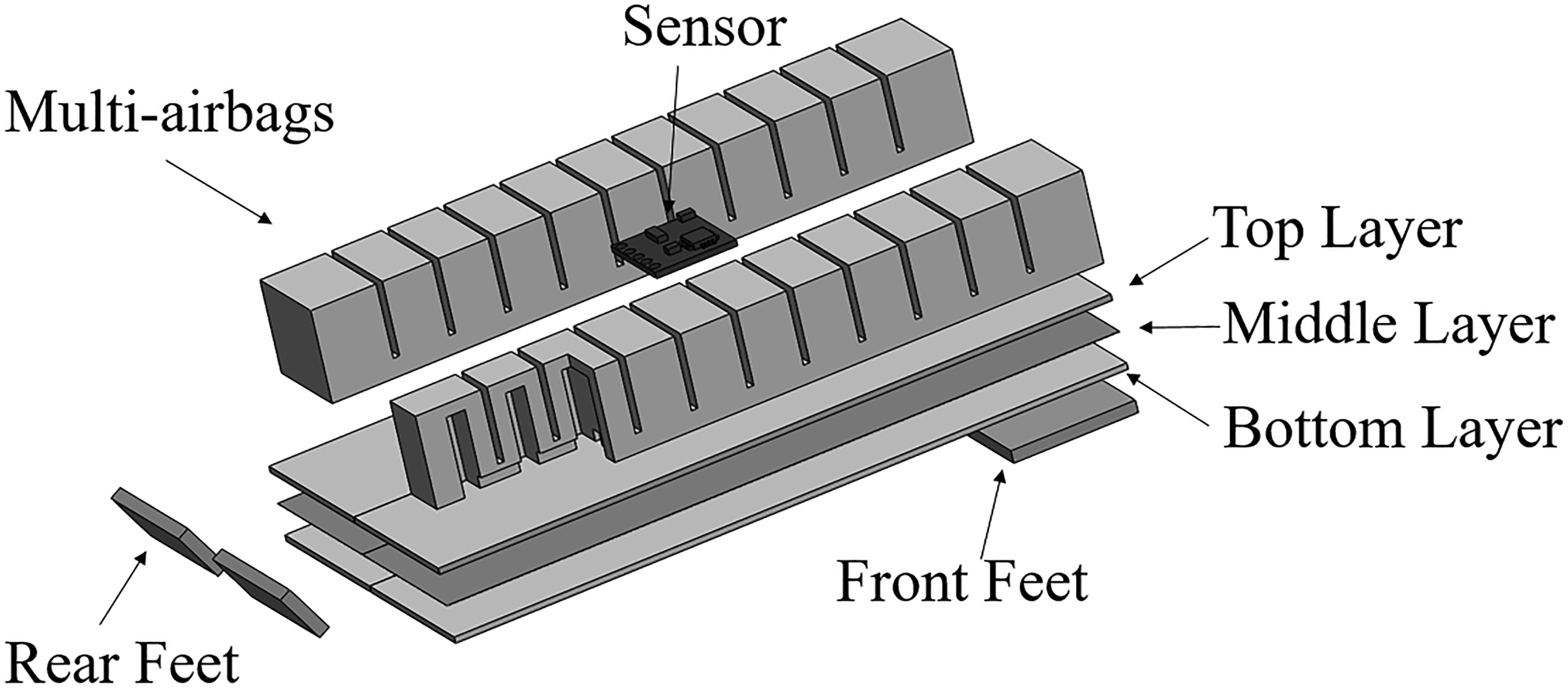
The explosive view of differential drive pneumatic soft robot.
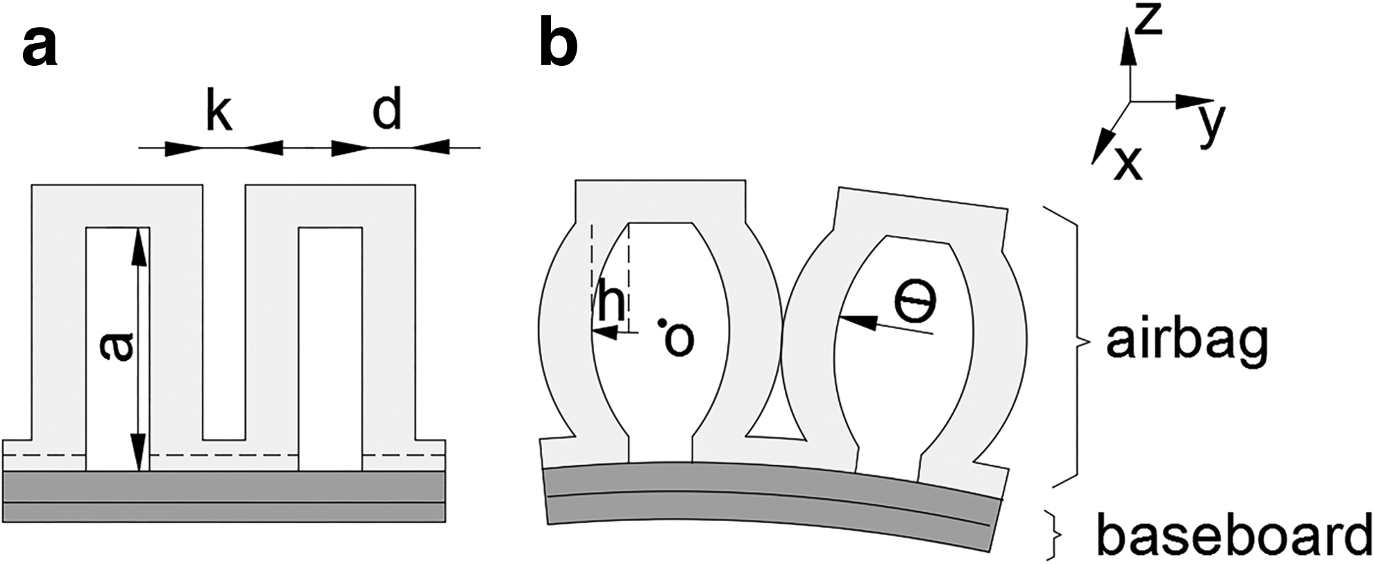
Cross section of two airbags,
In Figure 1, the three-axis electronic compass sensor is embedded in the middle of the actuators with silicone rubber. During the movement, the middle section will keep the sensor at a relatively stable state.
The differential device contains two columns of multi-airbags, and each of them is an actuator. There are 11 airbags in one actuator. Each airbag of one actuator is connected by the gas slot which is in the bottom of the airbags (Fig. 1). There are two tubes, and each tube is inserted into the middle airbag of the actuator. While inflating, the gas through the tubes reaches the middle airbag of the actuator and then reaches each airbag through the gas slot. At the same time, each airbag expands with the increasing pressure of the air chamber to drive the robot bends. The purpose of the middle layer is to prevent the baseboard expanding with the air chamber, but only bend with the actuator. The diagram of the inflated airbags is shown in Figure 2b; the length of the baseboard remains constant after inflating because of the paper layer. When the bending angles of the two actuators are the same, the differential drive robot makes a linear movement, otherwise the differential drive robot makes a turning motion.
The design of the airbags
The actuators of this robot are composed of multiple airbags (PneuNets17,18). The bending of the actuator depends on the inflating of the airbags. Thus, the design of the airbags is important. Figure 2 is the cross section of the airbags. The design of the airbags is based on the Yeoh model,
19
which is widely used on incompressible materials.
where W is the strain energy density function. E is the strain energy.
To get the displacement of any point in the inflated wall, we study one of the airbags. In Figure 2b, h is the maximum displacement of the airbag's inflated wall, and the coordinate origin
where a is the height of the wall. b is the width of the wall. And
To simplify the function, we construct the function
With all the functions above, the strain energy E can be obtained.
The functional relationship between the deformation h and the air chamber's pressure P can be calculated using virtual work principle. The strain energy of the inflated wall equals to the work of the pressure along the displacement of the Y-axis.
where
In this Equation (10), the deformation h increases with the pressure P. To achieve a larger deformation h and a smaller pressure P, a smaller thickness d is desirable. However, decreasing the thickness d will reduce the strength of the walls and reduce the maximum acceptable pressure. The thickness of the wall is selected as 2 mm. In addition, the deformation h increases with the height and the width of the inflated wall. However, to reduce the dimension of the airbag, a height of 12 mm and a width of 20 mm are selected. The deformation of the airbags causes the bending angle of the actuator. The distance k between the airbags reduces the expansion effect of the airbags, so a smaller distance k is desirable, and a distance of 1 mm is selected. The specific parameters of the airbag are summarized and shown in Table 1.
The movement patterns
The differential drive soft robot can not only move forward but also turn left and right. The different movement patterns depend on the different inflation sequences.
The linear movement pattern
The differential drive soft robot can move forward when the two actuators bend simultaneously. The structure of front and rear feet is shown in Figure 1. The front feet and rear feet are both two rectangular rubber plates, and the size of the feet comes from experiments. The front feet are attached under the baseboard. The rear feet are attached at the back of the robot, and the angle between the baseboard and the rear feet is 60°. In Figure 3, there are five modes in a linear movement cycle. State A shows the original position of the robot, in which the front and rear feet are at the deflated state. State B is the inflating process. During the inflating process, the contact area between the front feet and the ground is larger compared with the rear feet. In that case, the friction force of front feet is larger than the friction force of rear feet. Because of the larger friction force, the front feet are used as anchors. And the rear feet move forward with the bending of the actuators until the inflating process is finished. C shows the inflated state, at which the rear feet fully touch the ground and the robot meets the maximum bending curvature. However, the front feet and the ground are in line contact. At the deflating process D, the friction force of the rear feet is larger compared with the front feet. During the deflating process, the rear feet are used as anchors due to the larger static friction force. And the front feet move forward with the stretching of the actuators. State E shows the final position of the robot. The forward moving distance is H in one linear movement cycle. In general, this robot uses its front feet and rear feet sequentially as anchors when it bends and stretches.

The schematic diagram of the linear movement pattern.
The turning movement pattern
The differential drive soft robot makes a turning movement because of the different bending angles of the two actuators. To make a most efficient turning movement, only one of the two actuators is inflated or deflated during the turning movement process. Figure 4 is the schematic diagram of the right-turning movement pattern. State B is the inflating process of the left actuator. The front feet anchor the ground due to the higher friction force. And the left actuator meets the maximum bending curvature at the state C. At the deflating process D, the friction force of the left rear foot is higher compared with the right rear foot. Then, the robot deflects toward the lower frictional side and makes a right turning movement. With the method of independently inflating, the robot can get the maximum deflection angle. From the original state A to the finial state E, the robot makes a right-turning angle of
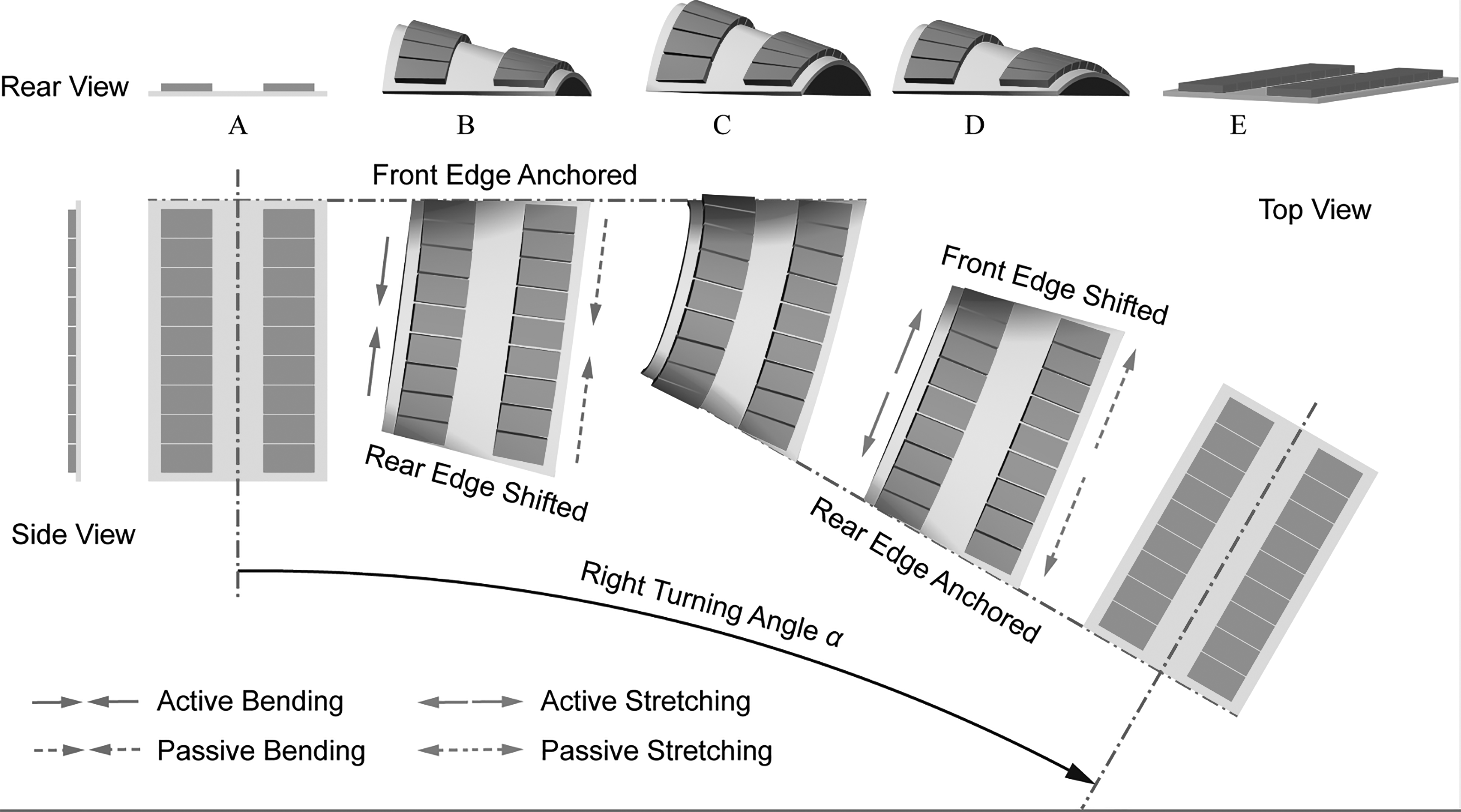
The schematic diagram of the turning movement pattern.
The RBF Control of Differential Drive Soft Robot
We establish the closed-loop control model to control the linear movement and the turning movement using three-axis electronic compass sensor and the RBF model. The purpose of the linear movement control is to keep the robot moving in the same direction. When the robot deflects from the original direction, it has the ability to self-correct. And the turning movement control is to make the robot turn to the specified deflection angle with the maximum speed. The RBF model is needed in the linear movement control and the turning movement control.
RBF is an artificial neural network that uses RBFs as activations, which is widely used to deal with the nonlinear partial differential equations. The differential drive soft robot is mainly made of silicone rubber, the expansion model of which is extremely nonlinear and complex. Instead of studying the nonlinear expansion mathematical model, we use RBF neural networks to study the turning ability of this robot on three different surfaces and create the mathematical mapping among frictional coefficient, deflection angle, and inflation time. Inflation time is essential for the closed-loop control of the robot, and to get the appropriate inflation time automatically, the working condition (frictional coefficients) and the azimuth angle are needed.
Figure 5 is the closed-loop control circuit of the differential drive soft robot, which mainly contains power source (DC12V), air pump (30 L/min), reduction valve, electromagnetic valves (MAC-35A), microcontrollers (Arduino UNO), and the soft robot. We use two two-position three-way solenoid valves to control two actuators' inflation and deflation. The inflation and deflation of the actuators are independent.

The closed-loop control system of differential drive soft robot.
RBF neural networks
RBF networks have three layers as follows: an input layer, a hidden layer, and a linear output layer. The input layer consists of the input vector, the hidden layer contains the nonlinear RBF activation function, and the output layer is a scalar function of the input vector.20,21
In RBF model, the neuron number of the input layer is n, represents the dimension of the input vector n, and the dimension of the output layer is m. From the input layer to the hidden layer, the RBF is commonly taken to be Gaussian:
where x is the input vector, ci is the center vector for neuron i, ui is the output of the neuron i,
The output of the networks is:
where yj is the output of neuron j in output layer,
At last, the input layer and the output layer can be expressed as (13). According to the input vector, we can get the output vector.
RBF networks are typically trained by a two-step algorithm. The first step is unsupervised, and we choose K-means clustering method. 22 The second training step is supervised, and we use the least squares method 23 to get the weight between the hidden layer and the output layer.
The control of differential drive soft robot
The RBF model of differential drive soft robot contains input layer, hidden layer, and output layer. The input vector contains the deflection angle
To collect the experimental data, we experiment on three different surfaces: the acrylonitrile butadiene styrene (ABS) plastic, the plywood, and the glass, as it is shown in Figure 6. Different surfaces have different frictional coefficients, which are 0.6, 0.7, and 0.8 by measuring. This RBF model can be applied to a variety of working environments with different roughness by adding the frictional coefficient as one of the inputs. We collect K groups of experimental samples by controlling the different inflation time and different surfaces and obtaining the corresponding deflection angle

Three different surfaces,

Experimental data (red circles) and RBF training data (surface) among deflection angle, frictional coefficient, and inflation time,

The RBF control logic diagram of differential drive soft robot.
According to the experiment, the maximum deflection angle is recorded as
The control of linear movement
The purpose of linear movement control is to keep the robot moving toward the initial direction. The robot can self-correct its azimuth angle when it deflects from the initial direction.
Step A: using the three-axis electronic compass sensor to record the initial azimuth angle
Step B: using the air pump to inflate the actuators synchronously with the maximum inflation time
where N is the inflation times of the self-correction phase,
And the deflection angle of each correction is:
Step C: we put the deflection angle
Step D: the robot is continuously moving in the same direction by repeating step B and step C.
The control of turning movement
The control of turning movement is to make the robot turn to the specified deflection angle with the maximum speed.
Step A: we give the robot a specified deflection angle
Step B: the azimuth angle after k times' deflection is
Step C: we repeat step B until
Figure 8 shows that to get the corresponding inflation time t, the deflection angle
Experiments and Results
These experiments are carried out under room temperature. The experimental devices include air pump (30 L/min), reduction valve, high speed electromagnetic valves (MAC-35A), control unit (microcontrollers and the printed circuit board), power source (DC24V), the air pipes (

The top view of the linear locomotion on the ABS plastic surface,

The top view of the turning motion on the ABS plastic surface,
Linear locomotion experiment
Figure 9 shows the linear locomotion process of differential drive soft robot on the ABS plastic surface. The distance of each grid on the experimental platform is 50 mm. In linear movement experiment, left and right actuators are inflated and deflated synchronously. After nine cycles' linear locomotion, the azimuth angle is detected by three-axis electronic compass sensor. If the robot deflects from the initial azimuth angle, the robot produces corrective movement, which is controlled by the control unit. Figure 9a shows the robot at the initial state. Figure 9b shows the position of the robot after nine cycles' linear movement. At this moment, robot deflects from the initial azimuth angle without the use of self-correction. Figure 9c is the self-correcting process with RBF model. Figure 9d shows the position of the robot after self-correcting process, the robot back to the initial azimuth angle.
Turning motion experiment
Figure 10 shows the left-turning motion process of differential drive soft robot on the ABS plastic surface. The aim of this experiment is to make the robot turn to the specified deflection angle with the maximum speed. In this experiment, we give the robot a 30° deflection angle to test the specified deflection angle turning ability. Figure 10a shows the robot at the initial state. Figure 10b shows the first inflation process. At this process, the bending of the left actuator is caused by the inflating of the right actuator. The rear foot of the right side can completely touch the ground to provide maximum friction force. Figure 10c is the final state after the whole turning process.
Results and discussion
The experimental data of the differential soft robot on three different surfaces are shown in Figure 11. Figure 11a shows the linear movement experimental data. The linear movement process includes nine cycle's linear movement and one corrective movement. After nine cycle's linear movement, the differential drive robot slightly deflects to the left side. And then the robot turns back to the initial direction after the self-corrective process. The deflection speed is proportional to the frictional coefficient, which can be seen in Figure 11a. However, the average speed in the initial direction is no big difference among different frictional coefficients. The linear displacement of the robot is about 192 mm after 10 cycles' locomotion (nine linear locomotion cycles and one self-correction cycle). The locomotion time is 19.5 s, and we can get the average moving speed which is 9.85 mm/s (in Fig. 9). And the robot is continuously moving toward the same direction with nine cycles' linear locomotion and one cycle's self-correction.

The experimental data of the differential soft robot on different surface,
Figure 11b shows the left-turning movement experimental data with different frictional coefficients. This differential drive soft robot has different turning ability in different surfaces. And the turning ability is proportional to the friction force between the robot and the ground surface. It takes the robot 13 cycles to finish the 30° turn on the ABS plastic surface with the frictional coefficient of 0.8. However on the plywood surface and on the glass surface it needs 16 cycles and 17 cycles, respectively. Under these working environments, the average turning speed is from 1.23 to 0.88°/s. This turning movement model has a high turning accuracy, which can be seen in Figure 11b. This RBF model can be applied to a variety of working environments with different roughness, not only the three surfaces.
Conclusion
In this article, a differential drive soft robot is built. It is composed of two columns of paralleled airbags, one baseboard, front feet, rear feet, and one sensor. This robot can perform differential motion, according to the different inflation time of the left and right actuators. Linear movement pattern and turning movement pattern are presented. RBF neural network model is used to train the turning ability of this robot. We collect the experimental data on three different surfaces: the ABS plastic, the plywood, and the glass and create the mathematical model about inflation time, frictional coefficient, and deflection angle. And the closed-loop automatic control model is established by the use of three-axis electronic compass sensor. Finally, the RBF neural networks model is verified by the linear and turning movement experiments. According to the experiment, this linear motion model can keep the robot moving toward the same direction, and the average speed of the linear locomotion is 9.85 mm/s on the ABS surface. In the above experimental condition, the turning movement model has a high accuracy rate, and the average turning speed is from 1.23 to 0.88°/s. Because of the robot's soft structure, it can be applied to the complex and varied natural environment. This robot could also be useful in earthquake rescue and reconnaissance missions where humans or rigid robots are not capable of accessing. Furthermore, to improve the accuracy of RBF neural network model, we will increase the experimental data by performing the experiments on more surfaces with different frictional coefficients. The future work will focus on the integration of this kind of soft robot and apply it to different environments.
Footnotes
Acknowledgment
This work was supported by National Natural Science Foundation of China (grant no. 51475300).
Author Disclosure Statement
No competing financial interests exist.