




Abstract
Abstract
A fully reconfigurable, pneumatic bending actuator is fabricated by implementing the concept of modularity to soft robotics. The actuator features independent, removable, fabric inflation modules that are attached to a common flexible but non-inflating plastic spine. The fabric modules are individually fabricated by heat sealing a thermoplastic polyurethane-coated nylon fabric, whereas the spine is manufactured through fused deposition modeling 3D printing; the components can be assembled and dismantled without the aid of any external tools. The replacement of specific modules along the array facilitates the reconfiguration of the actuator's bending trajectory and torque output; likewise, the combination of inflation modules with dissimilar geometries translates to several different trajectories on a single spine and allows the actuator to bend into assorted, unique structures. A detailed description of the actuator's design is thoroughly presented. We explored how reconfiguration of the actuator's modular geometry affected both the steady state and the dynamic characteristics of the actuator. The torque output of the actuator is proportional to the magnitude of the pressure applied. The actuator was excited by sinusoidal and square pressure inputs, and a second-order linear fit was performed. There were no perceived changes in its performance even after 100,000 inflation and deflation cycles.
Introduction
P
As an example of the fluidic actuator, the soft pneumatic bending actuator translates forces derived from pressurized air into a curling motion. Designs of fluidic actuation systems regularly overlook air as a means of pressure transmission due to its compressibility and, instead, employ water or petroleum-based oils. Nevertheless, air remains a popular choice in soft-robotic applications due to its inherent lack of hazardous effects, unparalleled availability, and comparatively negligible mass. These advantages are evident in several soft pneumatic bending actuators that have been developed for various applications.
These actuators are composed primarily of hyperelastic materials (such as silicone rubber) that are capable of sustaining high strain deformation with minimal degradation in structural integrity. The injection of pressurized air into specifically designed air channels causes predetermined sections of these channels to expand and deform as dictated by the geometry of the bounding surface. A common technique used to induce bending is to employ antagonistic elements that operate synergistically. Pressurized air acts on the boundaries of the expanding section that would usually cause linear motion of the actuator; however, this deformation is opposed by an inextensible restraining element that is paired to the expanding section. Such a pairing is arranged in a physically unbalanced manner and applies a bending moment onto the structure, which causes it to curl or bend.
Shepherd et al. 22 pioneered the Pneu-Nets bending actuator and the concept was quickly improved on by Mosadegh et al. 4 Other examples of bending actuators include the fiber-reinforced actuator,6,23 a bending actuator capable of withstanding extreme pressures developed by Yap et al. 24 and a rigidized beam. 25
The presence of complex geometries along the fluid path limits the available methods for fabricating these actuators. Currently, soft lithography methods appear to be the most widely used. 26 A preliminary mold is first used to produce a casting with the complex geometries of the air channels. This casting is then transferred to a secondary mold to seal the structure. The antagonistic element can be integrated into the elastomeric body2,4,5,8 or can be applied externally. 27 Additive manufacturing technology has also been applied to soft robotics.24,28,29 Actuators fabricated through this process are primarily homogenic and are mainly composed of only a single material, making it difficult to insert a separate antagonistic element. Careful consideration of the placement of material must be given to ensure that eccentric forces are generated on pressurization.
Current designs and fabrication methods usually result in the end-product having a fixed structure and functionality; most pneumatic bending actuators feature a fully integrated structure that does not allow for any post-assembly modification. As a result, current bending actuators are limited to a single actuation profile. However, practical applications require the characteristics of soft robotic actuators to be versatile and adaptable. 30 For instance, maintenance robots must be able to perform a number of dissimilar jobs in a single facility 31 ; soft robotic grippers attached to these robots must be able to handle all these tasks adequately. A soft robotic exoskeleton may also potentially benefit from an actuator's adaptability by allowing it to fit to the unique anthropomorphic measurements of various users. Adaptability and versatility enhances a soft actuator's economic viability since a single unit can be employed to accomplish various tasks, as opposed to having a specific actuator for each task.
One way to accomplish this versatility is to design the actuator with a high degree of modularity, so that its components can be readily reconfigured and replaced. Achieving such modularity has two significant implications. First, modularity in actuator design enables mass production of its components. 32 This can result in the cost-effective deployment of soft-robotic systems. Second, the reconfigurability of such an actuator (as a direct consequence of its modularity) permits control strategies to achieve certain desired actuation profiles.
De Falco et al. 8 was able to develop an actuator with the capability to trace assorted trajectories by embedding several pneumatic actuators into a single assembly, with each individual actuator requiring its own pneumatic line. Overvelde et al. 33 developed an inherently unstable segmented actuator that can radically alter its actuation profile on the addition of pneumatic segments. However, changing a single segment of their actuator affects the performance of every other segment and, thus, complicates the effective implementation of their system. Various modular soft actuators that are non-pneumatic in nature have also been developed. Mathijssen et al. 34 presented a series-parallel actuator with the ability for selective activation for performance variation.
To enhance modularity in soft-robotic actuators, we developed a novel pneumatic bending actuator that is fully modular and, hence, can be readily reconfigured post-fabrication. We achieve this modularity by connecting several independent inflatable modules to a common, flexible but inextensible spine. Both the kinematics and the kinetics of the actuator can be changed by removing and/or replacing a number of the modules in the actuator, with the key attribute that the effect of any such change is localized at the modified site. This enables the actuator to achieve a variable bending profile.
An overview of the design of this novel actuator and some initial experimental results of its performance have been summarized in an earlier article. 35 This article significantly extends those preliminary results by presenting a detailed description of the mechanism that grants the actuator its distinct modularity and intuitiveness, and a comprehensive treatment that describes the effects of the actuator's modularity on its mechanical properties. Specifically, we introduced a more detailed treatment of the structure of the modular, pneumatic, bending actuator capable of post-fabrication reconfiguration, including the locking method employed to mate the modules to the spine. We also demonstrated a variety of possible reconfiguration paradigms, as well as various bending geometries. Finally, we quantified the changes in both the steady state and transient properties of various actuators as their geometries are altered.
Actuator Design
The actuator functions by pneumatically and structurally connecting the independent inflation modules through a common spine. The spine itself is mainly constructed out of a flexible variant of thermoplastic polyurethane or TPU (NinjaFlex; NinjaTek, Inc.), and it is manufactured on a LulzBot Taz 6 fused deposition modeling 3D printer, using techniques established by Yap et al. 24 A 3D model is first generated by using industry standard computer-aided design packages, and it is translated into g-codes by the Lulzbot edition of Cura (GNU GPL). Table 1 lists the printing settings of the spine.
In contrast, the inflation modules can be fabricated by hand-using techniques that we have previously developed. 25 The modules are essentially pneumatically sealed fabric bladders; the fabric primarily comprised a nylon weave, attached with a TPU backing. During fabrication, a piece of fabric is first hand cut to size, and a circular hole is created. A barbed, pneumatic connector is then inserted through the hole, and it is sealed by applying a continuous bead of silicone epoxy (Silpoxy, Smooth-on) along the interface of the fabric and the connector; the module is then placed inside an oven and is cured at 60°C for 15 min. The module is then folded onto itself, and it is sealed on the top and side edges. Sealing is established by applying pressure using any hot metallic object (e.g., clothes iron and impulse sealer); the high temperatures melt and bond the TPU backing. The appearance of the components after fabrication is illustrated in Figure 1.

The actuator is composed of a common spine and multiple inflation modules.
After fabrication, assembly is performed through the insertion of the modules into the spine; tools are not necessary to assemble the actuator. Figure 2 illustrates the process of assembly. To begin insertion, a module is pushed down into the slot. The geometry of the slot itself is intended to interfere with the tip of the pneumatic connector. On insertion of a module, two sections of the slot deform to allow the connector to enter. Figure 2B shows the first section of deformation (the locking section) and deforms during the initial portion of insertion. As the connector is pushed further into the spine, the conical tip of the connector encounters a secondary hole (the pressure seal). The diameter of this hole is smaller than the dimensions of the conical tip, and the connector is forcibly inserted into the second hole. This difference in diameters is responsible for generating a pneumatic seal between the pressurized sections of the actuator and the atmosphere.

The modules are attached to the spine through simple insertion using the hands.
Insertion is completed when the locking section snaps back into place; at this time, there is no physical interference between the locking section and the cylindrical portion pneumatic connector; and the locking section is perfectly mated with the connector. However, the locking section acts as a physical stop, preventing any movement in any direction, and combats the effect of pressure forces onto the connector. As such, the pneumatic connector not only acts as a channel to distribute air but also serves as the structural member that holds the modules in place and prevents them from dislodging or ejecting. Due to the deformation caused by the connector, insertion of a module causes a minute bend on the actuator (∼3°/module).
The primary feature of the actuator is its ability to modify its bending trajectory based on the synergistic interactions of the various inflation modules installed. Figure 3 portrays a number of techniques that can be employed to vary the bending trajectory. We have previously proved that the trajectory and, by extension, the torque output of the actuator is primarily dependent on the magnitude of the pressure supplied to the actuator, and the geometry of the modules utilized. 35 When at rest, all modules are in a collapsed state. When a stream of pressurized air is injected to the actuator, however, the affected modules inflate to a geometry as designated by the design. It is paramount that there is significant intersection between the inflated geometries of the adjacent modules. This intersection generates contact forces that are then transferred to the spine, and it generates a bending moment that causes the spine to curl. The degree of bending can then be modified based on the characteristics of the inflation modules attached, with larger modules increasing the curvature of the bend, and smaller modules having the opposite effect.

Examples of the activated state of the actuator are illustrated. Changing the interference mechanics between adjacent modules creates a localized variation in actuation.
Combining inflation bladders of different sizes, thus, allows for a localized variation in curvature along the length of the actuator. It is, therefore, possible to configure the actuator to create different bends, unlike the traditional circular bending trajectory of established pneumatic bending actuators. Conversely, the inserted modules do not necessarily have to possess the capability to inflate; plugs may also be attached that simply seal the spine at the installed location. This creates a section in the actuator wherein no bending occurs and the segment will remain straight; however, the plugged section will be unable to apply or resist any forces, torque, or bending moment. The application of any external forces on the actuator, regardless of the point of application, will cause the actuator to bend at the plugged sections. If that amount of compliance is not desired, the actuator can instead be assembled with suitably sized modules so that these modules would be tangential to each other on inflation. Pressurization of an actuator configured, as such, will still result in a straight, localized section, but the section is now capable of resisting external forces. Combining these techniques results in unique bending paradigms and trajectories; several embodiments of the distinct capabilities of the actuator are seen in Figure 4.

Various heterogeneous bends were achieved by combining different inflation modules; the reference shapes are drawn in the white boxes.
Methodology and Results
Actuator variation
To explore the effects of the modular nature of the actuator on its performance, components of various geometries were fabricated; all the modules fabricated for the purposes of the succeeding experiments were designed to inflate as spheroids. In turn, these components were combined to create nine different designs with dissimilar geometric morphologies, with all other features (e.g., locking geometry and overall spine stiffness) held constant. Specifically, the following properties of the structure were altered: module count or the number of modules installed (n), module spacing (D), diameter of the module at the centroid (d), and the length of inflatable section of the module (L). These quantities are summarized in Table 2 and Figure 5.

n, number of installed modules; D, spacing between adjacent modules; d, diameter of the module at the centroid; L, length of inflatable section of the module.
By changing these parameters, the interaction properties between adjacent modules are also changed. Specifically, the force between the modules is highly dictated by the contact area of these modules and can be approximated by Equation (1), and the subsequent equations.
35
Table 3 lists the definitions of the utilized variables in these equations.
The free bending deflection of any actuator is determined by equating the bending moment resulting from the interaction of the modules, and the bending resistance of the modular spine.
The bending resistance (Mres) is dependent on the structure of the modular spine and was experimentally determined by using the method in Ref.
35
The spine we utilized had a bending resistance described by Equation (6).
Characterization platform
The majority of the experiments and measurements performed were accomplished by using a common platform (Fig. 6). One end of the actuator was mounted on a supporting structure by means of a screw clamp, rendering the supported side, or the “fixed end,” completely restrained from movement. During every experiment, the actuator was clamped 20 mm into the fixed end and was oriented in such a way that bending opposes the direction of gravity. On securing the actuator, an MEMS-based inertial measurement unit (STMicroelectronics LSM9DS1), or IMU, was attached to the fixed end to record any unwanted tilts or misalignment of the actuator; this measurement was necessary to correct any inaccuracies in the collected data due to a misalignment. The IMU is then attached to the “free end” and allows the platform to record its angular position in real time at a minimum sampling frequency of 140 Hz; this process is further explained by Figure 7.
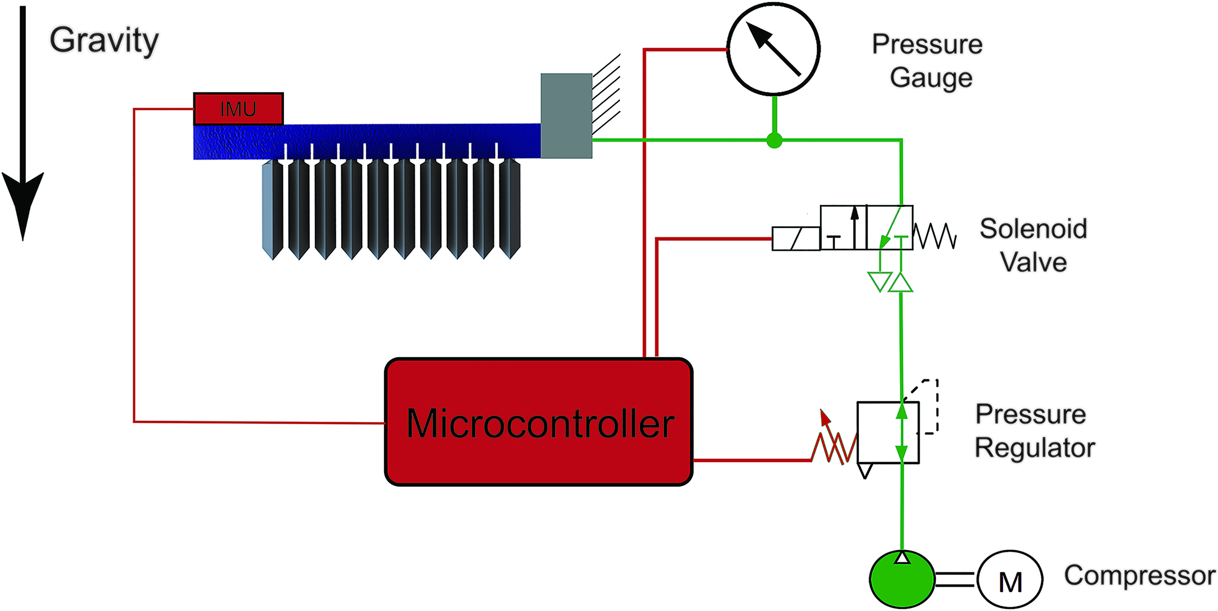
A schematic diagram of the characterization platform utilized for the majority of the experiments. A microcontroller simultaneously controlled the actuator and recorded the data from the IMU. IMU, inertial measurement unit. Color images available online at www.liebertpub.com/soro

Pressurized air is supplied by a compressor, whereas flow into the actuator is governed by a modified electromechanical pressure regulator (SMC Pneumatics, IR1000-01); the regulator itself is an off-the-self, purely mechanical, diaphragm-type regulator but is coupled to a stepper motor. The stepper motor consequently allows for the electronic control of any experiment utilizing the platform. Pressurized air from the regulator is then passed to a solenoid valve (SMC Pneumatics, S070) before being fed into the actuator; the solenoid valve provides the platform the ability to instantaneously pressurize or depressurize the actuator (e.g., non-unit step inputs or impulse inputs). Similarly, a pressure sensor (Freescale Semiconductor MPX5500DP) is attached to the pneumatic line of the actuator and simultaneously acquires data at the same sampling frequency.
The valve, the regulator, and the sensors are attached to a microcontroller board (Arduino, Mega 2560 R3) configured to perform both as a data acquisition module and control unit, allowing the full automation of all data acquisition activities. Each measurement taken with the platform was repeated three times.
Failure determination
Static pressurization tests reveal that the actuator can be reliably pressurized up to a maximum of ∼150 kPa before failure occurs. It was further observed that failure can present itself in two manners: by leaking or by module ejection. Rapid and sudden over-pressurization of the actuator resulted in the sudden, but temporary failure of the ejection lock and the expulsion of modules. Gradual over-pressurization of the actuator beyond 150 kPa only resulted in the leaking of air, overcoming the pressure seal; and, as such, the further application of higher pressures into the actuators will only result in a marginal and insignificant change in actuator position. Though the actuator can still function at this state, it is rendered uncontrollable and was considered as having failed. In some cases, gradual pressurization beyond 150 kPa still resulted in the ejection of the modules, though this phenomenon only occurred sporadically.
Fatigue testing was also performed to verify that the actuator can maintain its performance after multiple cycles. Three 5-module samples (design 9) were mounted onto the characterization platform and were applied with a square wave pressure input. A 5-module design was chosen to minimize the necessary frequency of the input as a higher module count corresponded to longer cycle times. 35
The inputs have peak values of 0 kPa and 100 kPa and were achieved by setting the regulator to a constant 100 kPa setting, and cycling the valve repeatedly. The cycling frequency was set at 0.125 Hz, and the experiment was run for at least 100,000 cycles. IMU readings were extracted after periodic intervals during testing, and Figure 8 shows the results. The recorded bending angle values did not deviate significantly during testing; the samples had a mean bending angle of 39.702° ± 1.128°. Discrepancies in the recorded values can be attributed to signal noise as well as to unavoidable external disturbances.

Results of the longitudinal fatigue testing. The graph shows the recorded bending angle readings of the three samples as the test progressed. Color images available online at www.liebertpub.com/soro
Static performance
An experiment was performed to determine how an unrestrained actuator will perform under static conditions, with its movements unrestrained. For each measurement taken, an identical sample was pressurized to its point of failure. The actual sample was then injected with a pressure of 5 kPa less than the failure point; the pressure was then reduced in 10% increments and was allowed to stabilize for 60 s. After stabilization, an IMU reading was recorded and the regulating system reduced the applied pressure once again. The cycle is repeated until the sample is completely depressurized.
Design 1 (Fig. 9A) was able to achieve an absolute bending angle of 194.210° ± 0.1564°. It can be seen that changes in the number of inflation modules installed aggressively affect the free bending performance of the actuator. Design 3 achieved a bending angle of 72.280° ± 0.808°, whereas design 2 only achieved 24.823° ± 0.448° at 150 kPa. Concurrently, (Fig. 9B, C) increasing the contact area offered a similar effect to the actuator due to the fact that the amount of force applied by adjacent modules is dictated not only by the pressure inside these modules but also by the magnitude of the contact area, with larger contact areas offering higher force outputs.

The results of the static free bending experiment as actuator geometry is varied. The dashed lines show the results of the predictive model.
Similar to the results presented in Ref. 35 analysis of the free steady state bending results immediately illustrates an actual limit to the amount of bending any such actuator can achieve. The bending rapidly rises at pressures of lower magnitude but quickly begins to taper off as pressure is increased. One consequence of such an interaction, however, is the relatively smaller increase of the bending angle in response to increasing pressure inputs due to the non-linear profile of the bending resistance of the spine, 35 compounded with the fact that higher bending angles will result in smaller contact areas due to the increased separation between adjacent modules.
Meanwhile, an area of note is the presence of significant deformation even after complete depressurization (i.e., 0 kPa). We suspect that the persistence of the deformation even after 60 s of depressurization is due to the viscoelastic properties of TPU. 36 Eventually, every sample returned to their original forms though a number of samples required as much as ∼180 s of rest. The results also indicate that the provided physical model sufficiently describes the static free bending performance of various configurations of the actuator. Though the model tends to over-estimate the actuators bending angle, it still successfully follows the characteristic trends in its trajectory. and is thus a useful tool in predicting the steady state performance of the actuator.
Another aspect of the actuator explored was its ability to carry loads; one measure that reflects this ability is an actuator's blocked torque output on pressurization. A separate experimental platform first utilized in Ref. 35 was adopted and is illustrated in Figure 10. An actuator was attached on two arms with one arm fixed to the frame, and a free arm connected to a carbon rod. The rod is then supported by two, low-friction ball bearings, anchored to the frame. The free arm is able to rotate freely and effortlessly but can be fastened to a static torque sensor (Forsentek, FT01) to facilitate torque measurement. For this experiment, the arms were kept in a straight position, translating to a 0° bending angle for the actuator, and with the midspan of the actuator coinciding with the center of rotation of the free arm. Five-millimeter-wide straps were placed in between each inflation module to fully restrain the actuator from bending.

The actuator attempted to curl on pressurization and applied torque unto the two arms; the now locked free arm then transmitted this torque measurement to the sensor. Similar to the general platform, an identical, customized, electromechanical pressure regulation system, and microcontroller board controlled and monitored the pressure in the actuator. The same microcontroller also received the torque sensor readings. Further, a pressurization procedure similar to the static free bending experiment was implemented; identical samples were also utilized in this experiment. The entire cycle is repeated three times for each sample.
Overall, all designs showed a highly linear correlation between the pressure input and the torque output, with the torque curves having a mean linear coefficient of determination of 0.9961 ± 4.452 × 10⁻³ as seen in Figure 11. It was observed during the course of the experiment, however, that the actuator can sustain significantly less pressure when loaded. Design 1 was able to sustain a pressure of 103.00 kPa ±1.84 kPa while delivering 2.68 N-m ± 0.14 N-m of torque. Design 8 sustained the least pressure at 53.73 kPa ±0.69 kPa, delivering 1.80 N-m ± 0.02 N-m.

The results of the static torque experiment. Color images available online at www.liebertpub.com/soro
Meanwhile, variations in the configuration of the actuator are instinctive. Increasing or decreasing the number of inflation modules results in a proportional change in the torque output of the actuator due to the corresponding increase or decrease of the moment arm. However, the increase in the number of inflation modules also reduces the maximum pressure an actuator can contain, with design 4 only sustaining 77.21 kPa ±0.18 kPa with a torque output of 3.02 N-m ± 0.05 N-m. We suspect that the early onset of failure is due to the possible inconsistencies in the alignment of the modules during assembly. When the misaligned modules are inflated and make contact, these misalignments create a secondary force component that increases the magnitude of the ejection forces on the pneumatic connector; however, an in-depth investigation is beyond the current scope. Analogous to the previous results, increasing the contact area also increased the torque output for a given pressure input but also decreases the maximum pressure.
Dynamic performance
Some applications, particularly those in an industrial setting, may necessitate the rapid actuation of a robotic device utilizing the actuator and, as such, the actuator's transient response was also measured. Each actuator variant was excited with sinusoidal pressure inputs of various frequencies; these frequencies ranged from 0.005 to 2 Hz, with peak-to-peak values of 0 and 100 kPa, having durations lasting for at least three cycles. For these measurements, the characterization platform was modified to increase the response time of the platform. We utilized a fully electronic pressure regulator (SMC Pneumatics, ITV0031-2US) to generate the sinusoidal input, whereas the remaining portions of the platform remained unchanged. The results of these measurements are summarized in Figure 12. Alternatively, we simulated the step response by cycling the solenoid valve to generate slow square waves (8.33 × 10⁻³ Hz). The lower peak of the square waves was held constant at 0 kPa, whereas the higher peak was increased incrementally from 15 to 150 kPa. The results of these measurements are summarized in Figure 13.

The time domain response of the actuator due to sinusoidal excitation.

The bode diagrams of the various design variants. The derived transfer functions comparing actual actuator pressure to bending angle are superimposed. The actuator's bandwidth varies exponentially with the total inflated volume of all the attached modules. Color images available online at www.liebertpub.com/soro
Examination of the time-domain waveforms for the sinusoidal inputs (Fig. 12) shows that both the trajectory and pressure curves of design 1 also resemble a sinusoid. However, a more detailed observation of these waveforms reveals that the inflation and deflation characteristics of the actuator are asymmetric—the lower peak of the trajectory waveform resembles more of a sawtooth, whereas the higher peak is similar to a typical sine function. This discrepancy is not present in the pressure waveform. The difference between the two peaks is consistent with the static free bending test and can be attributed to two primary factors: the decreasing available contact area as the bending angle increases, and the exponential correlation between the spine's bending resistance and the bending angle.
Meanwhile, the application of higher frequencies resulted in the attenuation of the bending angle response. Application of frequencies beyond the actuator's bandwidth reduced the maximum bending angle that the actuator was able to achieve—these waveforms prevented the actuator from reaching its steady state trajectory. Geometry variations also significantly altered the actuators' bandwidth. We have previously demonstrated that the number of the attached inflation modules negatively influences the actuation speed of the actuator, 35 with additional inflation modules decelerating the rate of inflation; specifically, the total volume of the attached modules affects the bandwidth exponentially, whereas module spacing only contributes a minimal effect (Fig. 13). We estimated the bandwidths for designs 2 and 7 using linear extrapolation, whereas linear interpolation was used for the rest of the variants. The decrease in bandwidth can be attributed to the increased amount of air that is needed to be injected in the actuator. Moreover, a second-order linear system fit, in the form of a transfer function, was done to quantify the response of the actuator variants; each of the fitted transfer functions' zero and poles are listed in Table 2. The fitted functions match the experimental data's gain and phase values in the bode diagrams to a large extent, with the exception of design 1's plot.
Application of the square wave pressure inputs illustrated in Figure 14 indicate that the actuators resemble that of an overdamped, second-order system. However, the response times are clearly dependent on the magnitude of the pressure input, with rise times differing as much as 4.9 s at 15 and 150 kPa (design 8). Overall, the actuators exhibit an inversely proportional relation between rise times and applied pressure. Such a correlation is, indeed, expected as the physics of the actuator dictate that the application of higher pressures translate to the generation of stronger forces and by extension, greater acceleration of the spine's structure. It can also be observed that the utilization of larger modules, and application of an increased number of modules negatively affects rise time. This behavior is consistent with the previous results.

The results of the square wave excitation as actuator geometry is varied.
In addition, further scrutiny of an extended portion of the response to a square wave reveals the asymmetry between inflation and deflation trajectories (Fig. 15). The deflation section of the trajectory has a more relaxed curve when compared with the inflation section, and this disparity is not present in the pressure waveforms. The asymmetry can be primarily attributed to the dissimilarities between inflation and deflation conditions. During inflation, the applied positive pressure applies a constant force on the actuator that is opposed by the elasticity of the spine. The opposing force is at a minimum when the spine is straight and, as such, the net force on the actuator is at its maximum at the beginning of inflation. The conditions during deflation are contrasting due to the fact that the pressure inside the actuator and the forces it generates are constantly declining as the spine straightens, which correspond to a slower deflation curve.

The full response waveform of the square wave excitation experiment as applied to design 1 at 0–100 kPa.
Discussion
The use of independent inflatable bladders as modular components in a pneumatic, bending actuator significantly extends its capabilities. Typical pneumatic bending actuators suffer from short fatigue life; reconfigurability is effectively insignificant for such devices due to the fact that the device may fail soon after reconfiguration due to its fragility. In contrast, our actuator can sustain its level of performance even after 9 days of persistent usage. In the event that failure does occur, we have observed that failure events have no effect on the capabilities of the actuator. Leaking actuators can return to their normal operating parameters once pressure has been returned to normal levels. Actuators who suffered from module ejection also behave in an identical manner wherein the reinsertion of these modules will see the failed actuator return to regular operation as well. Both instances of failure have no effect on quantitative performance metrics and, in fact, we were not able to detect any dissimilarities, whether visually or mechanically, between newly fabricated actuators and those who have suffered failures.
Careful selection of dissimilar modules allows the actuator to be mechanically programable and thus, trace diverse bending trajectories without the need to redesign and reconstruct the device. The simplicity of the underlying mechanism to vary the actuator's operational characteristics allows a user to easily tune its steady state performance. An increase in the contact area of the attached modules will result in greater torque outputs and more pronounced bending trajectories; this relationship is, indeed, predicted by the provided static model. As seen in the free bending results, particularly of designs 7 and 8, a 10-mm increase in the inflation diameter of the attached modules doubled the actuator workspace even if only six modules were attached; its blocked torque output also experienced a 100% increase. However, the results from the Dynamic Performance experiments show that the application of larger modules, or the installation of additional modules, resulted in a decrease of actuation bandwidth, as evidenced by the exponential correlation between total module volume and bandwidth (Fig. 12). As such, a designer must carefully balance the steady state characteristics of the actuator and its ability to achieve its steady state condition in a timely manner.
Meanwhile, the blocked torque output showed a highly linear correlation to applied pressure. This linearity suggests a simple control architecture will suffice if the actuator is operated in a completely static manner. However, both the steady state free bending results and the magnitude-dependent step response times indicate that the actuator is a highly nonlinear system when spatially unrestrained. Nevertheless, the fit of the derived second-order transfer functions' magnitude bode diagram (Table 2, Fig. 12), to that to the measured responses' diagrams suggests that the linearized system can be reliably predicted by these transfer functions. Their poles also indicate that the actuator behaves as an overdamped second-order system with an extremely dominant slow pole. This further simplifies the necessary control algorithms that are required to effectively use the system.
Conclusion
We presented a modular, pneumatic bending actuator that is capable of post-fabrication reconfiguration. Multiple, independent, replaceable inflation modules are attached to a common, flexible but inextensible spine. The reconfigurability of the actuator allows it to trace multiple bending trajectories without refabrication. This increases the versatility of the actuator by translating this reconfigurability into the ability to tune not only its bending trajectory but also its blocked torque output and dynamic characteristics as well. We have shown how variations in bladder configuration affect its bending performance. Geometry variation is achieved by leveraging the modularity of the described actuator. Operational performance can be easily and intuitively altered by replacing modules along the array; the interaction between these modules controls how the actuator behaves and is primarily driven by the magnitude of the contact area between the adjacent modules and the inflated volume of the modules themselves. The blocked torque output of the actuator can be proportionally controlled by the supplied pressure. Though an unrestrained actuator behaves as a nonlinear system, the derived second-order transfer functions show that it is possible to linearize the system and simplify its operation. Though these functions are suitable for most applications, the simplified transfer functions are not able to capture the richer dynamics of the actuator and thus, further investigation of an analytical model is warranted.
Footnotes
Acknowledgment
This work was supported by the Singapore Millennium Foundation (R397-000-258-592).
Author Disclosure Statement
No competing financial interests exist.