
Abstract
Abstract
Fluidic mechanisms have stimulated research and development in minimally invasive surgery instrumentations, because of their good performance in limited size and their force/torque generation with respect to other types of actuation systems. Fluidic solutions can be divided in two major classes: (i) elastic fluidic actuators and (ii) piston–cylinder actuators. Elastic fluidic actuators generate lower forces with smaller displacements; nevertheless, piston–cylinder solutions require seals, which can generate friction and require maintenance costs for a good reliability. The proposed solution is based on a hybrid soft–rigid actuation, which aims to overcome the limitations of both previous solutions while preserving the main advantages of the overall fluidic approach. This approach results in very compact, powerful, and low-cost actuators, which are highly customizable and adaptable to specific constraints, in medical applications but even beyond. This article proposes a novel design of hybrid soft–rigid actuators to be used as basic mechanical joints for enabling pitch and roll degrees of freedom for a miniature robotic arm. Forces up to 1.4 N and up to 2.77 N have been obtained for the above joints, respectively, and even better performance can be reached (up to 3 N) with further improvements, as demonstrated in this article.
Introduction
R
In recent years, research for MIS tools has shown a growing attention to implementing and introducing fluidic actuators, which can provide interesting performance in terms of generated stroke and force in endocavitary applications, even at small scales. 2 Fluidic actuators enable compact and efficient solutions, offering advantages with respect to other types of actuation, last but not least being more silent, lightweight, and normally lower cost. 3 They are often more adaptable to medical constraints than traditional motors, which require bulky gears and distal mechanisms, depending on direct-drive or tendon-drive actuation approaches, respectively. Differently from shape-memory alloys and thermal actuators, fluidic solutions operate at ambient or body temperatures. Unlike electrostatic actuators, piezoelectric, electromagnetic motors, or electroactive polymers, fluidic actuators do not require electrical connections, being safer and usable in the presence of radioactivity or magnetic fields (e.g., under MRI).4–6
For these reasons, several novel robotic arms and manipulators based on fluidic actuators have been developed for different applications over recent years. An interesting example is the BionicCobot robot produced by the company Festo Ag. & Co. 7 It has been developed by assembling seven pneumatic joints characterized by two antagonistic pneumatic chambers. This allows a stiffness regulation and a safer human–machine interaction.
Several soft continuum robots, based on fluidic actuation or obtained by combining it with tendons, have also been develeped.8–10 These systems take inspiration from nature with the aim to overcome limitations of rigid structures and obtain infinite degrees of freedom (DoFs). Among them, an interesting example has been provided by Hawkes et al. 11 They designed a pneumatic soft robot which navigates constrained environments through the growth of a thin membrane. Such solution fits in a very good way the requirement of robots at centimeter scale or more.
In general, fluidic actuators can be divided in two major classes: elastic fluidic actuators and piston–cylinder ones.2,6 The first class is characterized by inherent compliance and high backdrivability, which are fundamental features for the safety of MIS procedures. Nevertheless, these actuators have the main drawback of generating low forces compared with the piston–cylinder ones. Elastic fluidic actuators include membrane actuators, balloon actuators, bellow actuators, and artificial muscles or fluidic artificial muscles (FAM) (Fig. 1). 12

Classification for elastic fluidic actuators.
Membrane actuators are simple corrugated diaphragms which are deformed by injected fluid (Fig. 1a, b).2,13 This configuration is not able to limit the stroke in a preferential direction and results in a very limited mechanical efficiency, with limited displacements.2,13,14 Balloon actuators are based on 3D balloons, placed in joint position, which allow a bending motion by their isotropic strain (Fig. 1c, d).2,14 Nevertheless, these actuators are able to produce larger displacements, they are characterized by very low forces. Indeed, to produce high output forces, high inlet pressures are required, with the risk of bursts. Consequently, more robust body walls are necessary, thus further limiting the stroke and the overall system efficiency.
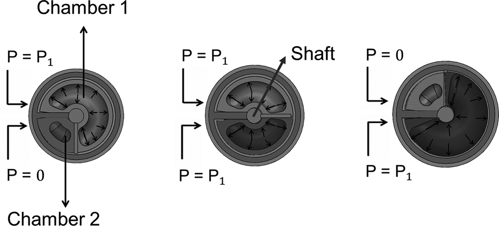
Bellow actuators are characterized by a folded geometry that retains the strain in a specific direction. An interesting solution is represented by the STIFF-FLOP actuator (Fig. 1e).5,14,15 It is constituted by a silicone cylindrical actuator with three equally spaced chambers for the fluidic actuation, and a central one, for the integration of a granular jamming chamber devoted to stiffness tuning. The fluidic actuator is hosted into an external bellow structure, which limits the radial strain thus enhancing the longitudinal one. This system can generate a linear or a bending motion. Another interesting bellow actuator, this time rotary-type, is shown in Figure 1f. 16 It is very similar to vane fluidic motors, but it is characterized by two folded elastic chambers. Due to the folded configuration of the system, the height of the vane has to be higher than the radius for guaranteeing the mechanical stability. For this reason, a slim configuration is not possible. In general, when thin and long, bellow actuators have stability problems and their production process is more complicated than for other types of elastic actuators.
In FAM, braided fibers or other organized structures translate an isotropic strain of a balloon into a contraction (Fig. 1g, h).17,18 These are the elastic actuators able to achieve the largest forces, 19 but they generate strokes which are limited to the initial actuator length (the maximum stroke is about 15–20% of the initial actuator length). 20
Other actuators use circular fibers around the elastic structure rather than bellows. 21 An example of a rotary actuator made by this technique is presented by Fras et al. 22 The main problem in this case is that, when the chamber is strained, these fibers separate and they cannot constrain anymore the radial expansions, with the high risk of bursts. 14
Piston–cylinder actuators generate large forces and displacements, but they require low friction seals for an appropriate working, which are challenging to manufacture, especially in miniaturized systems (Fig. 2). In fact, traditional contact seals, such as O-rings, cause high static and dynamic friction. 23 A possible solution is the use of clearance seals, based on very tight tolerances. Therefore, for guaranteeing zero leakages, tolerances have to be in the range of 1 μm or less 24 and this involves high production costs. Moreover, the friction is high, although lower than O-rings, and in the presence of eccentricity, leakages increase. A very high accuracy is required during the assembly phase. Another alternative is the use of liquid seals, but they support only low pressures and have to be combined with clearance seals to obtain acceptable values for the inlet pressure. 25 Finally, hermetic seals, made of rolling layers, which isolate the driving fluid, can be also used. An example of a vane fluidic motor characterized by two balloons, used as hermetic seal, is described in Pourghodrat and Nelson. 26

Seal solutions for piston–cylinder actuators (adapted from De Volder and Reynaerts 2 ).
The objective of this article is to present the design and the validation of a hybrid soft–rigid fluidic actuation system. It aims to overcome the limitations of fluidic solutions reported above by integrating two soft actuators into a rigid yet simple mechanical structure, which appropriately shapes the elastic parts during actuation. This concept is close to a hermetic seal solution, but it differs from traditional hermetic seals with regard to the use of rolling membranes, which have been replaced in this work by soft actuators. A first example of such approach is presented in Izzo et al., 27 where the hybrid concept has been used for realizing a normally open surgical end effector. This system is characterized by a compliant soft actuation system, entirely within a rigid gripping mechanism. The soft actuator is in contact with a rigid piston-like structure, which translates up and down in dependence on its strain. A pretensioned elastic band lets the gripper open since it undergoes a major lever of tension when the gripper is closed. The gripping force is 5.78 N at 0.2 MPa. However, in that case, the return system is based on the stored elastic force of the soft actuator and of the elastic band. It makes the elastic reopening of the gripper slow and difficult. No antagonistic solutions have been proposed for that mechanism.
Materials and Methods
Concept and design overview
To obtain a valid alternative to the fluidic actuators described in the previous section, the hybrid soft–rigid concept proposed in this work has to comply with several constraints.
The devised concept has to preserve the compliance and the high backdrivability, typical of the elastic class and fundamental for all MIS applications. At the same time, the efficiency of the elastic system has to be preserved and large strokes must be generated. Dedicated structures which could make difficult the manufacturing, for example, inextensible braided fibers, have to be avoided, but the strain has not to be isotropic.
Compared with traditional piston–cylinders, the hybrid concept aims to overcome the problems of the seals, thus limiting friction forces and permitting to obtain a low-cost system, at least in principle. This is a relevant advantage for MIS applications, where disposable tools at low cost are more and more requested. Another important aspect is the possibility of applying high inlet pressures, which permit to produce high output forces (see Concept and design overview section), which are desirable even for performing basic surgical tasks. For the same reason, the force used for the strain of the soft actuator itself has to be kept low. The output force target depends on the surgical application. For example, transanal endoscopic microsurgery (TEM) requires force less than 1.5 N. 28 In laparoscopy, manipulation and retraction forces range from 5 N up to 10 N, but they are not normally achieved in miniaturized systems. Nevertheless, for most tasks in endocavitary surgery, such as tissue manipulation and cutting, forces in the range of 1–2 N are sufficient.29–31 Peirs et al. verified in vivo that the maximum peak force for suturing skin, muscle, and liver tissue is 2.3 N. 32 Thus, the target output force can be a couple of Newton, at least for a proof of concept.
The mechanical structure has to be simple to minimize production costs and facilitate the assembly phase. The final solution should result in very compact actuators, which are highly customizable and adaptable to specific sizes, imposed by medical constraints. For general applications in MIS, the actuators should have a diameter ranging from 12 mm for MIS or NOTES (Natural Orifices Transluminal Endoscopic Surgery) applications 15,29,33 to 30 mm for SPL (Single Port Laparoscopy) applications. 34 For a preliminary design, a diameter of 14.5 mm was considered to facilitate the prototyping phase and the proof of feasibility. Indeed, actuator designs can be scalable down to 10 mm or less, since there are virtually no mechanical limitations differently from traditional systems (i.e., traditional motors, cable mechanisms, and traditional contact seal fluidic solutions).
Two identical soft components have been integrated in a single hybrid soft–rigid actuator to enable bidirectional motion of the joint (Figs. 3 and 4). In this way, traditional problems of pure soft actuators (i.e., unmanageable elasticity of the soft material) are overcome. Thanks to the presence of two identical soft components, a pressure control can be applied in each of them to reach a specific joint position with a specific force, thus enabling the actuator bidirectional movement and an antagonistic behavior. Once the desired position has been reached, by increasing the pressure in each chamber, the stiffness increases in turn; consequently, a controlled stiffness variation can be obtained. Thus, at low inlet pressure values, the system preserves compliance and high backdrivability, which are fundamental features when taking the instruments in or out of patient's body, especially in emergency cases.5,35 At the same time, high stiffness can be reached during surgical procedures, allowing greater output forces and more precise movements.

Schematic representation of the actuation working principle for the pitch motion (
Schematic representation of the actuation working principle for the roll motion (
The selected fluid flowing in the soft actuator chambers depends on the desired characteristics of the final system. In general, pneumatic actuators are characterized by a low viscosity and are lighter than hydraulic ones. This is a huge advantage in miniature channels, to prevent high pressure losses caused by viscous flows. The use of air or CO2 is less harmful in the event of leaks, which can affect other electronic or mechanical components, the long-term maintenance is easier, and it prevents the problem of the return lines since the exhaust gases are not to be collected. 4 On the other hand, hydraulic actuation is characterized by a lower compressibility of the fluid and, consequently, by a larger force and an improved accuracy in positioning. 2 In general, hydraulic actuators, driven by physiological liquids, are safer during surgical procedures, while reducing the risk of bursts. However, in hybrid soft–rigid actuators, the rigid structure prevents from bursts and also leakages are limited, thus combining advantages of the abovementioned actuation systems, both hydraulic and pneumatic.
In an initial proof-of-concept phase, air actuation is simpler to be implemented, thus air has been used as driving fluid in this work. Other physiological liquids could be employed.
Considering the above described specifications, basic modular joints (pitch and roll) have been designed for integration into a multi-DoFs tool for MIS, thus providing higher dexterity and flexibility for different surgical tasks. The actuators exploit the deformation of two identical soft actuators, due to fluid pressure inlet, to produce a mechanical effect onto a rigid structure in which soft actuators are embedded (Figs. 3 and 4). This results in high compliance and backdrivability. In addition, the effective directionality of soft actuators is preserved since there is the rigid external structure to contain the strain within a predetermined range. It permits also to apply high inlet pressure and to change the system stiffness.
Hybrid soft–rigid actuators are hermetic, and then they support both hydraulic and pneumatic actuation and do not require seals. Stringent tolerances of the manufactured mechanical parts are not necessary anymore (except for limiting the surface friction of the rigid structure), thus resulting in low production costs. In addition, low-cost devices can be disposable, thus improving safety and reducing contamination risks.
EcoFlex 0030 silicone (Shore A; Smooth-On, Inc., Macungie) has been used for the soft actuators to limit the portion of the output force necessary for the material strain. In fact, this material provides high deformation with low pressures. In addition, it is biocompatible, low cost, and even resistant to high temperatures during possible sterilization processes. 36
The actuators' design aimed to minimize the volume of silicone parts to obtain more compact actuators still showing a good range of motion. In both joints, the rigid structure is characterized by a fixed part used to contain the soft actuators, and a mobile one on which the soft actuators act. The rigid structure for the pitch actuator is shown in Figure 5. In this case, the mobile part is a fork coupled with a shaft characterized by a plate on which the two soft actuators work in antagonistic configuration. It has a ±180° range of motion. Also, in the roll rigid structure, there is a shaft with a plate, on which the two soft actuators act (Fig. 6). The range of motion is again ±180°. SolidWorks CAD (Computer Aided Design) software has been used for the design of the joints.

Rigid structure of the pitch actuator.

Rigid structure of the roll actuator.
Thanks to their small size and intrinsic modularity, these two joints can be combined freely to obtain different robotic tools for specific surgical tasks.
Static model of the hybrid soft–rigid concept
Modeling the soft–rigid concept helps to steer and improve the design phase and to set up appropriate validation processes. For this reason, a theoretical model has been implemented for estimating the appropriate geometry of the soft actuators, which allows a minimum initial volume of silicone, yet being able to generate the movements of the rigid structure and the output forces required for a specific task. In addition, the theoretical model permits to obtain a relationship between the inlet pressure and the displacement of the joint, useful for the control system. As in Bao et al., 37 a static model has been applied. For the initial phase, a cylindrical soft actuator in a rigid cylindrical structure was considered (Fig. 7). It is characterized by an internal empty cylindrical chamber that expands under the effect of pressure.

Schematic representation of the hybrid soft–rigid actuator considered for the model.
The force equation is the following:
F is the output force, P the inlet pressure, Fa the friction force between the silicone chamber and the internal part of the rigid structure, and Fs the elastic force of silicone. Fa can be written as:
Fs can be written as:
In this way, when the output force is equal to zero, P can be written as:
Considering the stretch
This model allows for the analysis of the relationship between the inlet pressure and the silicone elongation when the structure is constrained within a rigid structure.
Starting from it, the same approach can be used to find a relationship between the inlet pressure and the rotation angle in rotary actuators (Fig. 8).

Schematic representation of the hybrid soft–rigid model in a rotary configuration.
Indeed, considering the initial and the final angles
Also in this case, according to the volume conservation principle, it is possible to obtain
Then, the relation between the inlet pressure and the final angle can be written as:
Considering the stretch
With the objective of completing Equations (10) and (16) and leaving only the pressure (P) and the stretch (
Manufacturing of hybrid soft–rigid actuators
Fabricating the hybrid actuators requires different steps. The first one consisted in the manufacturing of the soft parts by casting techniques. Molds have been designed considering sizes established in the previous paragraph, and then they have been produced by a 3D printer machine (3D SYSTEM PROJET HD 3000). Once the molds have been realized, part A and B of EcoFlex 0030 have been mixed (1A:1B by weight) and, to eliminate bubbles, the mixture was left for 10 min in a vacuum pump, poured into molds, and again put in the vacuum pump for 10 min. Finally, it was cured at 60°C for 3 h. The final soft actuators are shown in Figure 9.
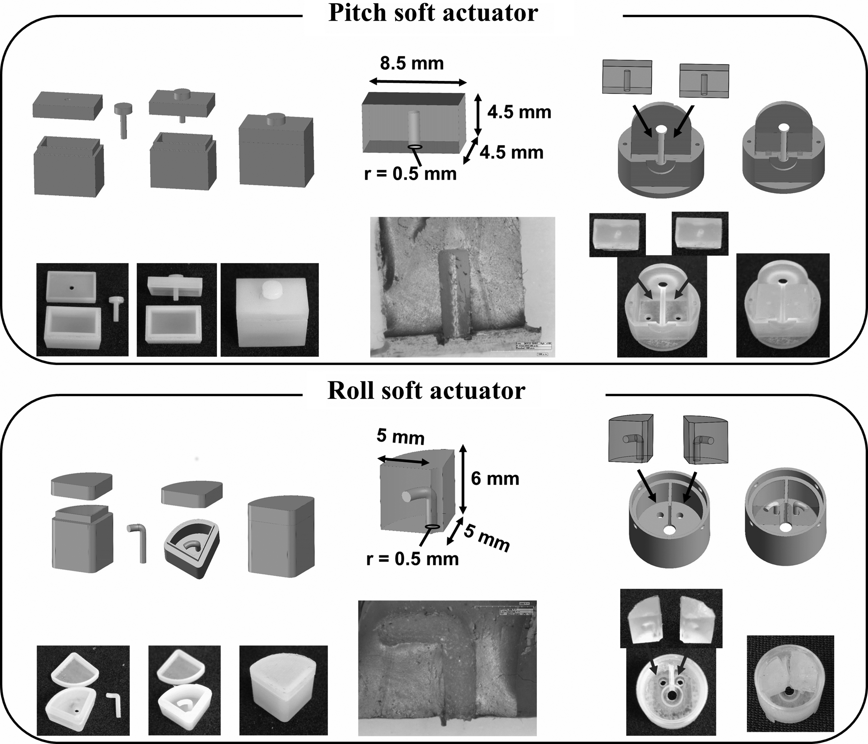
Top, mold and assembly for the soft actuator of the pitch joint; below, mold and assembly for the soft actuator of the roll joint.
The two soft actuators unconstrained by the rigid structures and just expanding with air pressure like balloon actuators are shown in Figure 10.

The second step was dedicated to the fabrication of the rigid parts, which were realized by using the 3D printer again, at least for this preliminary phase. In fact, the objective here was to obtain rapid prototypes for qualitative tests and for confirming the proposed working principle.
The third step was the integration of the soft actuators in their respective rigid structures and their connection with tubes using a silicone glue, “Sil-Poxy” (Smooth-On, Inc.). Final actuators are shown in Figure 11.

Results
Material characterization
To verify the described model, the mechanical properties of the silicone EcoFlex 0030 have been investigated to obtain the formulation of the tension (
Uniaxial tension and compression tests were carried out by an Instron Materials Testing Machine. The sample geometry was a standardized 2-mm-thick dumb-bell test piece ASTM (American Society for Testing and Materials) number D412 Type C for tension tests. These tests were carried out with five samples for each silicone type, subjected to five loading cycles at 400% engineering strain level and 10 mm/min speed deformation. For the compression tests, five cylinders with a diameter of 20 mm and a height of 20 mm were used for both materials. For each sample, five tests have been done at 75% engineering strain level and 10 mm/min speed deformation. Then, the mean engineering stress–strain curves have been evaluated for both silicones (Fig. 12a, c).

On the basis of these data, the true stress–strain curves of EcoFlex 0030 and EcoFlex 0050 have been calculated (Fig. 12a, c), using the formulations reported below:
A computational/experimental approach was applied to compare four theoretical models for silicones (Neo-Hookean, Mooney–Rivlin, Yeoh, and Ogden Model), based on a nonlinear theory of the elasticity, and to identify the model that best replicates the trend of the true stress–strain curve.38,39 In this way, it is possible to obtain a formulation of the silicone true stress, in terms of tension (
A MATLAB script was used to identify the material constants of the four theoretical models. The model which best replicates the trend of the stress–strain curves is the Ogden one for both EcoFlex 0030 (Fig. 13) and EcoFlex 0050 (Fig. 14 and Table 1).

Comparison between engineering tension

Comparison between engineering tension
R2 Values for Different Theoretical Models
By supposing a uniaxial stress condition, the Ogden model is based on the Principal Cauchy Stress equation reported below, which depends on the stretch
Equation (13) can be used for the true tension (
Model validation
The model validation has been carried out to verify the ability of the theoretical model to replicate the hybrid soft–rigid concept. The final aim was to compare the relationship between the inlet pressure and the elongation described by Equation (10) with the experimental values. For this reason, experimental tests were done by replicating the system geometry described in Figure 7. In this cylindrical system, the external radius of the tested soft actuator (re) was 4.5 mm; this is constrained by the presence of the rigid structure, with which it is in contact. The rigid structure has been produced by the 3D printer machine using the same material of the joint rigid parts, that is, the VisiJet M3 Crystal (3D system, Rock Hill, SC). The initial radius of the internal chamber (
In the experimental setup, an electronic proportional microregulator (Series K8P; Camozzi spa, Italy) was introduced to control the inlet pressure. The microregulator enables to control the pressure coming from a traditional air compressor (model JUNIOR 30; ABAC). The imposed inlet pressure was read from a digital pressure sensor (Series SWCN; Camozzi spa). The elongation was measured by an electronic caliper, placed by a system of vices. Experimental tests were carried out on five samples, to improve statistical significance. For each sample, five tests were carried out by increasing the inlet pressure from 0 to 0.2 MPa, that is, sufficient to test the proof of feasibility of the actuators. The final mean curve, compared with the plot of Equation (10), is shown in Figure 15.
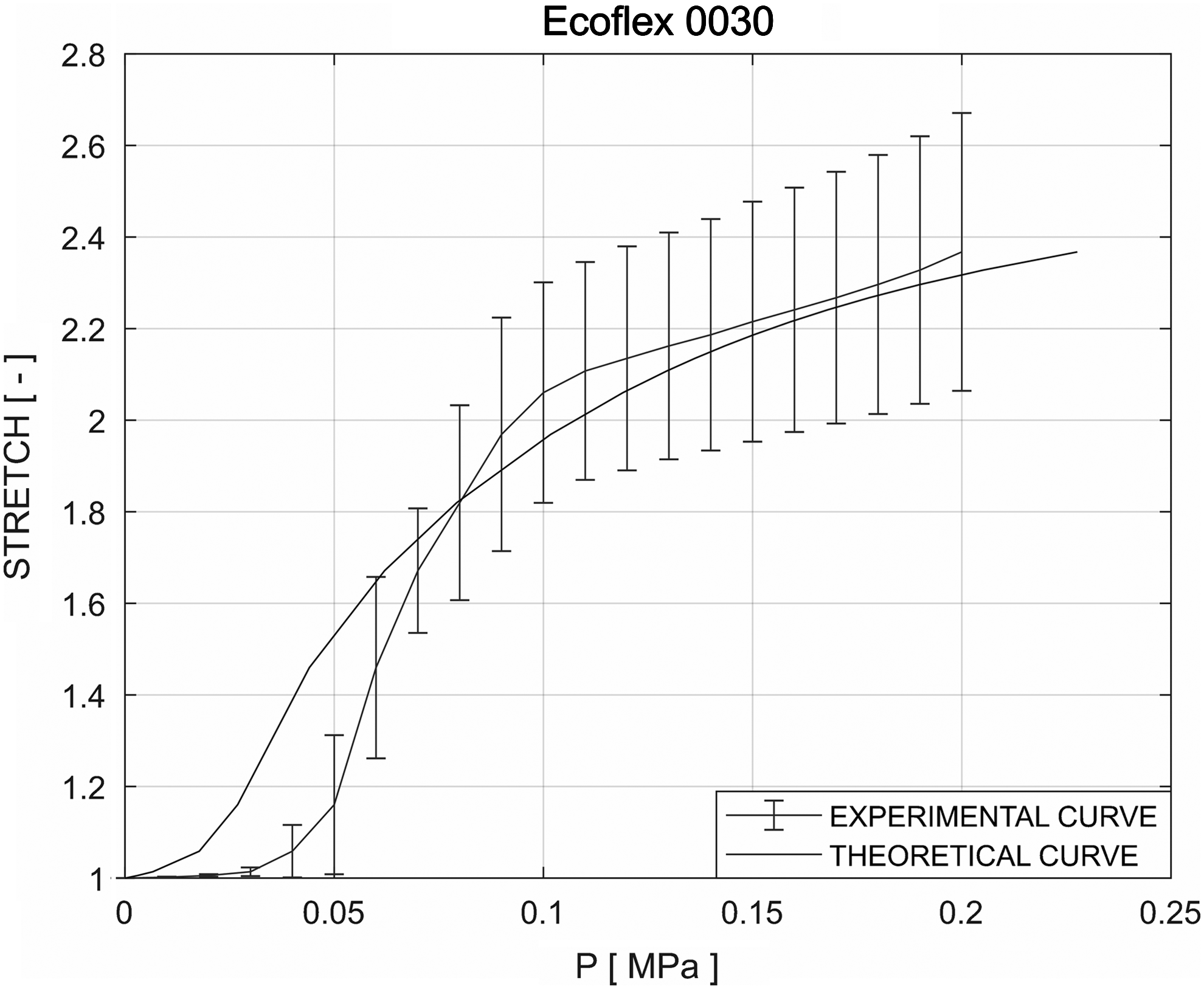
Comparison between the experimental curve and the theoretical static model for EcoFlex 0030.
The model replicates approximately the experimental curve (R2 = 0.9343). The main drawbacks of the model are probably related to the selected approximations. As described above, uniaxial tensile and compression tests were carried out to obtain a formulation for the stresses of the soft material. These values were evaluated in a configuration, which did not reflect the cylindrical geometry of the model. Consequently, although the Ogden model adequately catches the experimental stress–strain curve of the silicone, this curve is measured in a different configuration with respect to the final model, thus affecting the final results.
For testing the model, all tests described above were replicated also using the EcoFlex 0050. The result is shown in Figure 16 (R2 = 0.9040).

Comparison between the experimental curve and the theoretical static model for EcoFlex 0050.
To verify the applicability of the model also for the developed rotary joints, experimental tests have been carried out with the Aurora® EM Tracking system by placing the localization probe on the pitch/roll actuator. The inflated pressure in the soft actuator was increased at steps of 0.01 MPa until the actuators achieved the final position (Fig. 17). At each step, the position of the localization probe has been registered. This measurement was repeated three times for each joint.

Comparison between the experimental curve and the theoretical static model for the pitch
The comparison between the theoretical curve, obtained adapting the model to the design of the joints [Eq. (16)], and the experimental curve is reported in Figure 17 (R2 = 0.8158 for the pitch actuator, R2 = 0.8423 for the roll actuator).
Output force experimental tests
Experimental tests have been carried out to measure the performance of each soft actuator integrated in the rigid structures in terms of force. The output forces were evaluated with a dedicated experimental setup, which includes a commercial six-axis load cell (Nano17; ATI Industrial Automation). At the beginning of each test, the pressure in the soft actuator was increased until the external rigid structure reached the configuration which was under investigation. Then the load cell was placed in contact with the rigid structure and locked to the mobile part of the actuator through screws as show in Figures 18 and 19. The pressure in the soft actuator was increased at steps of 0.01 MPa, thus evaluating the force exerted on the load cell. The pressure ranged from 0 to 0.31 MPa. The inflated soft actuator pushed on the plate and the force was transmitted to the mobile part through the shaft. For each soft actuator, tests were carried out five times and the mean values were calculated.

Force–pressure curve of pitch (position 0, position 1, position 2).

Force–pressure curve of roll (position 0, position 1, position 2).
Pitch output force experimental tests
Output forces were measured in different configurations, to understand how a single soft actuator acts in different positions. In fact, the value of acting forces changes from a position to another, also at the same pressure inlet.
Position 0 is when the soft actuator is not strained and the fork is parallel to the base (Fig. 18). In this configuration, the elastic force of the silicone is equal to zero and the area on which the pressure works is the smallest.
In position 1, the soft actuator is strained and the fork is in vertical configuration (Fig. 18). The module of the elastic force is larger than zero, since the soft actuators are strained.
At the position 2, the soft actuator is at the maximum strain permitted by the rigid structure and the fork is in the opposite configuration with respect to the zero one (Fig. 18). The module of the elastic force reaches its greatest value, but also the area on which the pressure works is the largest.
By these tests, it was possible to evaluate the forces that each soft actuator integrated in the rigid structures is able to produce in the three main configurations.
Roll output force experimental tests
Also for roll experimental tests, the output forces were measured in the three main configurations.
Position 0 is when the soft actuator is not strained (Fig. 19). The elastic force is zero and the area where pressure is applied is the smallest. At position 1, the soft actuator is strained and it produces a rotation of 90° (Fig. 19). The module of the elastic force is larger than zero. Finally, at position 2, the maximum strain of the soft actuator is reached (Fig. 19).
Variable stiffness tests
Thanks to the antagonistic arrangement of the two soft elements integrated in each actuator, the actuator stiffness can be regulated by controlling the two inlet pressures.
To carry out variable stiffness tests, the two soft chambers have been positioned in an equilibrium position (represented as 0° in Fig. 20a, c), by setting the pressure at 0.075 MPa in both soft components. Then, their mobile parts have been forced to span an angle of 90° by using a robot arm on which a commercial six-axis load cell (Nano17; ATI Industrial Automation) was mounted (Fig. 20b, d). Subsequently, the same tests have been replicated by setting the pressure in both soft components at 0.15 MPa.

Experimental setup of stiffening variation tests for pitch actuator (schematic representation
Figures 21and 22 show the start and end positions of the actuators and how they move under load.

Bending of the pitch joint under the load applied by the robot arm.

Rotation of the roll joint under the load applied by the robot arm.
The obtained results are shown in Figure 23 for the pitch actuator and in Figure 24 for the roll actuator. The stiffness variation, calculated as the ratio of the maximum difference between the two curves (

Stiffening variation curve of pitch.

Stiffening variation curve of roll.
In future, stiffening variation curves will be evaluated also for higher inlet pressure values, thanks to the use of more robust rigid structures (not 3D printed).
Potential application in MIS
Once the feasibility of the approach is confirmed, the two actuators were connected into a surgical manipulator. Four DoFs (Pitch, Roll, Pitch, Roll) were integrated in a serial configuration to obtain a redundant robotic arm, 29 with a total length of 70 mm (Fig. 25). To have a functional device, a gripper was connected on the tip of the system as End Effector (Fig. 27). It is based on the hybrid soft–rigid concept and described more in details in Izzo et al. 27

Design of the four DoFs surgical manipulator. DoFs, degrees of freedom.
Thanks to their modularity, the two designed joints can be combined in different ways to achieve the desired performance, as demonstrated—with different actuation mechanisms—also in Tortora et al. 29
A preliminary prototype of the manipulator has been realized by 3D printing (Fig. 26).

Prototype of the surgical manipulator.
The Denavit–Hartenberg parameters of the robots are listed in Table 4. The reachable workspace for the manipulator (considering the reference frame showed in Fig. 25) is reported below in Figure 27.

Reachable workspace for the manipulator, including the four DoFs (Pitch, Roll, Pitch, Roll) and the gripper.
Denavit–Hartenberg Parameters of the Robot
Discussion
Based on preliminary tests, force values range from 1.4 N of the pitch to 2.77 N of the roll, depending on the specific actuator position. These values are more than acceptable for selected MIS procedures as TEM, 28 and for dedicated tasks in endocavitary surgery, 29 such as cutting. These forces are larger than those available in rigid manipulator robots, as in Tortora et al. 29
The model of the hybrid soft–rigid concept has been carried out through a theoretical analysis. The relationship between inlet pressure and displacement (in length and thickness) of a cylindrical structure has been investigated.
Preliminary variable stiffness tests have been carried out, demonstrating the stiffness tuning capability of the actuators.
The feasibility of the proposed approach has been confirmed, resulting in very compact actuators that are highly customizable and low cost. At this stage, the fact that rapid prototyped parts have been used for the actuators has to be considered. Rigid parts were characterized by limited mechanical resistance and high friction, which caused a decrease of the overall efficiency. In particular, this happens for the pitch, where the force was exerted by the fork, and not directly by the mobile shaft on which the soft actuator acts. In fact, the inaccurate coupling caused by the rapid prototyping determined an inefficient transmission of the forces. Tests should be repeated by optimizing the efficiency of the system, using CNC machined prototypes, and improving the connection points of the pneumatic circuit, for minimizing air leaks. Rigid structures, realized by more accurate techniques and different materials, would allow an increment of the performances by improving surface finish and reducing the friction force.
An optimization of the internal chambers is also essential. It will allow an increment of the output forces, by enlarging the internal area on which pressure acts. This will be done always considering the need to have a minimum initial volume of silicone, but able to produce the required movements of the rigid structure, as it has been done in this case.
Conclusions and Future Work
The main objective of this work is to present a new concept of actuator for laparoscopic tools based on a hybrid soft–rigid fluidic system. This approach results in very compact actuators that are highly customizable, high power, and low cost. The objective was to design traditional joints, that is, pitch and roll, characterized by a large range of motion for guaranteeing high dexterity and flexibility in an articulated manipulator obtained by their integration. For both actuators a ±180° range of motion is obtained. Thanks to the presence of two antagonistic soft actuators in each joint, by adjusting the input pressure, it is possible to achieve and maintain all positions comprised within this range and regulate the stiffness of the joints at the same time. 35 The soft actuators have been manufactured using silicone EcoFlex 0030. However, the use of other stretchable materials is possible. Rapid prototyping was carried out to validate the concept and then a model has been implemented. The relation between pressure and position was investigated through a theoretical model. It was developed to characterize the behavior of such actuators, with the purpose to improve the actuators design in future evolution. In particular, the model can be used also to understand the minimum initial volume required to obtain specific range of motion and output forces. Thus, the mechanical behavior of silicone EcoFlex 0030 has been analyzed with a computation/experimental approach, and the balance of forces acting in a hybrid actuator has been considered. The obtained model allows a good approximation of the experimental curve. Prototypes of pitch and roll basic joints have been manufactured to confirm the feasibility of the approach. They were tested to evaluate the output forces, which range from 1.4 N of the pitch to 2.77 N of the roll. These hybrid actuators, obtained by integrating mechanical and fluidic solutions, will be improved with the aim to obtain systems presenting both the advantages.