
Abstract
Abstract
There are a number of instances in nature where long and slender objects are grasped by a continuum arm spirally twirling around the object, thereby increasing the area of contact and stability between the gripper and the object. This paper investigates the design and modeling of spiral grippers using pneumatic fiber-reinforced actuators. The paper proposes two reduced order models, a pure helical model, and a spatial Cosserat rod model to capture the deformed behavior of the gripper using the mechanics of fiber-reinforced actuators in the presence of self-weight. While the former model can yield closed form expressions that aid in design, the deformation parameters deviate by greater than 40% of its length for actuators longer than 200 mm. However, the Cosserat rod model deviates by less than 8% of its length for two different prototypes validated in this work. The deformation of the gripper is then correlated to the number of spiral turns achievable about the object, which determines the quality of the grip. Together, they enable a systematic framework where the gripper parameters can be designed for a given range of object sizes to be handled. This framework is experimentally validated by successful gripping of a range of slender objects that lie between a 20 mm diameter tubelight and a 60 mm diameter PVC pipe.
Introduction
S
In contrast, there are a number of instances in nature where structural contact between two objects is achieved when one body spirally twines around the other, thereby maximizing the area of contact. For example, grapevine tendrils grow spirally around a long and slender tree stem 4 for increased structural support. Elephants (Fig. 1a), snakes, and cephalopods also demonstrate spiraling to capture objects or preys. The key advantage of spiraling is that it generates a large area of contact with relatively small gripper volume. There are a number of practical applications where the object to be manipulated is long and slender. For example, underwater deep sea exploration 5 may require grippers that spiral around objects such as corals. In agricultural applications such as in de-weeding or uprooting of a shrub, a spiral grip on the stem could result in robust manipulation (as shown in Fig. 1c). This paper explores the working design and modelling of a soft pneumatic spiral gripper (Fig. 1d).

Examples of gripping long and slender objects.
Related work
Recently there has been a steep rise in the number of soft robotic grippers reported in literature. Some of the earliest work using soft fluidic actuators were presented by Suzumori et al., 6 where finger-like bending behavior is used to grip small objects including mechanical tools. More recently, Ilievski et al. 7 developed a pneumatically actuated starfish gripper to manipulate delicate objects like an egg. Most of these grippers and their variants function by fluid induced bending6,8 of soft stretchable chambers that are differentially constrained. Using this principle, a soft under actuated hand has been developed, 3 which is capable of robust grasping of different shape and sizes of objects. The concept of granular jamming9,10 is used to stiffen the hold of the grippers on objects of various sizes. More recently, there have been grippers that provide feedback of the object size. 11 With all these developments, state of the art soft grippers still find long and slender workpiece objects difficult to grasp, 3 necessitating exploration of newer concepts that are biologically inspired.
In rigid robots, the concept of whole arm manipulation 12 has been demonstrated to effectively handle relatively large objects using the entire body of the manipulator. Whole arm manipulation leads to a larger contact area between the gripper and the object, thus better distributing the contact forces. Semi-soft continuum manipulators, such as the OctArm,13,14 have demonstrated this by spirally wrapping around the object. More recently, a single actuation boa type fiber-reinforced soft actuator 5 has been developed to grasp deep sea coral reefs of different sizes and varied fragility. The boa gripper utilizes spiral coiling, and this was shown to generate larger pulling force than a finger-like bellow counterpart. In this paper, we investigate a design framework for creating grippers that can spirally coil along long and slender workpiece objects.
Approach
This paper uses the concept of pneumatically actuated Fiber Reinforced Elastomeric Enclosures (FREEs).15–17
FREEs are quintessential building blocks for soft robots, as they encapsulate fundamental constituents of designs in literature and nature, namely stretchable skins, fibers, muscles, and pressurized fluids. The most simplified representation of a FREE is a hollow cylinder made of stretchable elastomer material and reinforced with two families of fibers denoted by angles

FREEs and its design space:
Preliminary investigations focused on mapping the spiral deformation to the constituent fiber orientations using kinematics alone, neglecting the effects of loading, and the strain energy stored in the elastomer. 20 On the other hand, high fidelity computational mechanics-based models that capture the soft interaction between pressurized chambers, grippers, and objects can be complex, offering little design insight. There have been other intermediate approaches proposed, where the FREE actuation is captured using simple axisymmetric models,21,22 and a global reduced order model such as Cosserat rod is used to capture interaction with external forces.23,24 In this paper, we will first extract the design insights using the idealistic helical model, and then update our understanding using the Cosserat rod theory by taking into account its self-weight due to gravity. This paper thus proposes and experimentally validates two simplified mechanics-based models to analyze and design a FREE-based spiral gripper.
The analysis methodology is used to present a design space for spiral FREEs that maps its fiber orientation, size, and geometry parameters to the range of objects that can be successfully gripped. The design space qualitatively predicts the conditions for successful gripping without accurate estimations of gripping force, its distribution, friction, etc. This design space is deemed useful in several applications, 16 and this is demonstrated by an example where a spiral FREE gripper is designed to handle objects of varying diameter.
The paper is organized as follows. First, we present the materials and methods involved in fabricating and modeling a spiral FREE. This includes experiments for determining the elastomer properties, and incorporating them into Cosserat rod theory with the inclusion of gravity loading (details of the Cosserat rod theory are provided in Appendix A1). Next, we apply the methods to study gripping criterion using FREEs and map them to the fiber orientations. Then, we experimentally validate our proposed analytical methods. Following this, we present an example of a design problem. Finally, we end with conclusions and future work.
Fundamentals of Spiral FREES
Simple reduced order models indicate that two families of helically wound fibers yield a kinematically well-constrained system.
25
These two families of fibers span a design space denoted by angles
Spiral FREE design and fabrication
Two dimensional (planar) and spatial deformation modes can be achieved by the addition of a third fiber constraint to the base elastomeric structure. For example, Figure 3a–c demonstrates that the addition of a single straight fiber to an extending actuator can result in planar bending (Fig. 3b). Similarly, adding a single straight fiber to an extending-rotating actuator can exhibit spiral motion
16
(Fig. 3c). We intentionally refer to the deformation as a spiral and not a helical, as the latter occurs in the ideal scenario where there is no self-weight or any other acting external force. A detailed set of possibilities may arise by adding a single fiber at any angle γ to the FREE structure as presented by Bishop-Moser and Kota.
16
For ease in analysis and design, in this work we consider FREEs exclusively with a single straight third fiber (

Spatial deformation of FREEs using a straight fiber and modeling. Demonstration of
The construction of the spiral FREE starts with a base layer of natural rubber latex tubing (Part No: a038132-025, Latex-Tubing.com). Fibers are then wound in a semi-automated fashion with the desired angle and orientation. Adhesive agent (Part No: 74725A12, McMaster-Carr) is applied to cement the fibers on the base latex tubing. Finally, this matrix is cured to obtain a composite structure. 21 The actuator is tested to evaluate its material properties (more on this will be detailed in the Governing equations section). Then, a straight fiber is glued to this actuator using the adhesive agent to convert the extension and rotation into spiral motion.
Governing equations
The governing equations of FREEs are simplified by assuming cylindrical geometry for both the undeformed and deformed
22
configurations. For the design space considered for the spiral gripper, this is a reasonable approximation as no substantial radial changes are observed upon actuation. The deformation parameters are represented as stretch ratios
In these equations,
In pneumatic actuation, the input is usually controlled by air pressure. We can relate applied pressure to the FREE deformation by considering the energy stored in the elastomer. We assume that the elastomer tube behaves as a Neo-Hookean or MooneyRivlin hyperelastic solid. The strain energy stored per unit volume u is expressed as a function of the first invariant (I1) of the Cauchy-Green strain tensor, which are in turn expressed in terms of the stretch ratios as:
where C1 and C2 are material constants. The third stretch ratio
Volume of the actuator V and volume occupied by the elastomer material Vt are given by:
All the terms shown in Equations (3)–(7) can be expressed in terms of only one deformation ratio
where
In Appendix A2, we compare the model developed in this subsection with experimental results for pressure P versus extension (
Once we have the information of extension parameter (
where
Gripping Using Spiral FREEs
The efficacy of a gripper is determined by its ability to restrict relative motion between itself and the object even under the presence of external forces. 26 In grasping literature, the term force or form closure is commonly used to indicate the number and type of independent forces required to constrain the object.26,27 The FREE gripper meets force or form closure conditions by spiraling about an object as shown in Figure 4.
The three possible cases of spiral gripping.
Quality of grip: three scenarios
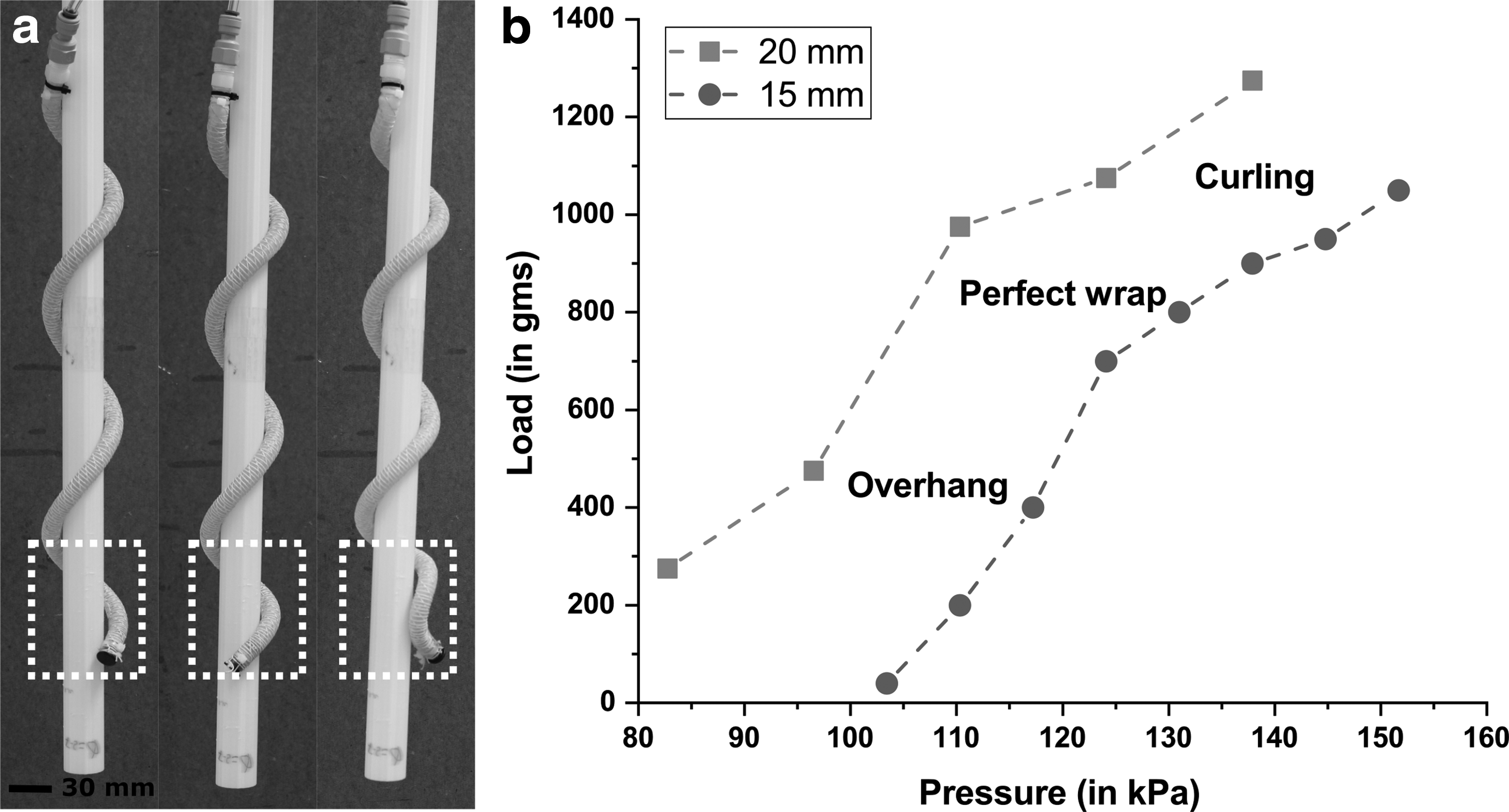
Consider a FREE spiral gripper undergoing several turns about the cylindrical object that it grips. The quality of grip is a measure of how uniformly the FREE conforms onto the object. To better highlight these scenarios, we experimentally evaluate the gripping force as a function of the input pressure for a FREE gripper operating on two cylindrical objects of radii 15 and 20 mm, respectively (Fig. 4b). The gripping force is the maximum axial force applied to the object to break away from the hold of the gripper, and is found by placing dead weights on the cylinder ends. We observe three scenarios.
1. Overhang: This indicates that a part of the FREE length may not contact the object as shown in Figure 4a (left insert). This is because at lower pressures, the spiral is just forming, and does not exactly conform to the object. This corresponds to the initial part of the curve in Figure 4b where the gripping force increases slowly with pressure. This scenario is disadvantageous, as it may lead to lower contact forces, and in extreme cases may fail gripping for not meeting the force closure criteria.
2. Perfect wrap: At a certain optimum input pressure the entire length of the actuator is in contact with the cylindrical object. This may correspond to the nose of the curve in Figure 4b, where there is a sudden increase in the slope of the force versus pressure curve. This is the scenario that we will strive to attain. This paper presents guidelines for attaining perfect wrap.
3. Curling: When pressure exceeds beyond the perfect wrap case, the end section of the actuator curls. At these pressures, most of the FREE length resist deformation, and maintain their spiral configuration due to contact with the cylinder. However, the contact of the FREE tip is still relatively weak, and this tip deforms further by bending. Curling may be characterized by a decrease in the slope of the force versus pressure curve at higher pressures as seen in Figure 4b. Curling is not detrimental, yet suboptimal as part of the FREE length does not involve in gripping. At higher pressures the onset of curling may lead to unwinding of the spiral as seen in Figure 4a (right insert).
For a good grip, we envision the entire actuator length involved in restricting the object from relative motion. Using the criteria for a perfect wrap, we present a method to determine range of workpiece diameters that the FREE can grip for acceptable input actuation pressures and/or acceptable strains in the elastomer. As a simplifying assumption, we will consider the deformed profile to be a pure helix, 16 and then extend the design rules for more general and realistic deformation that includes the effect of gravity.
Modeling spatial deformation of spiral FREEs: helix assumption
In an ideal scenario where no external forces act, spiral FREEs deform helically with a uniform pitch and radius along its length when pressurized. In this scenario, the radius of the helix reduces and the number of turns increases as a function of applied pressure. The helix radius and the maximum number of turns may be limited by the FREE deformation: stretch ratio
A pure helix is formed due to the combination of a uniform curvature
The radius of the cylindrical workpiece
The curvature
The equation reveals that the minimum workpiece radius decreases with decrease in fiber angle

Insight into selection of fiber angles using the helix assumption. For a given axial stretch of the spiral FREE,
However, this alone does not ensure successful grip. Recent literature on continuum manipulators have shown the ability to achieve form closure by forming a spiral around an object with less than one complete turn provided there is a non-negligible friction in the grip.28–30 Such a gripping configuration restrains the object from all sides with sufficient contact points, thus ensuring form closure. However, because the friction coefficient is unknown, or to account for the conservative scenario of very low friction coefficient, we aim for slightly greater than one complete turn around the object as the necessary and sufficient condition for gripping.
To successfully spiral around the cylinder forming one complete turn, the FREE must have a certain minimum length. If the spiral were a perfect helix then the length of the FREE for n turns around the cylinder is given by:
where
The above equation determines the minimum permissible slenderness ratio (
The lower limit on the workpiece length
Figures 5a–c yield insight into the selection of the fiber angle, radius, and length of the FREE actuator, and the corresponding workpiece sizes that it can grip. For example, using the curves of Figure 5c, a FREE with β = 60° and radius
Mechanics-based modeling of spiral FREEs
To motivate the need for a mechanics-based model that accounts for the effect of gravity loads, we compare the ideal helical deformation of the FREE 16 and the exact deformation profile with the consideration of self weight under gravity (Fig. 6a). The former has a constant pitch, whereas the pitch of the latter varies with length. It can also be observed that the error between the two shapes is small for small FREE lengths, 31 whereas for longer lengths, the mismatch is significant. In this paper, we envisage long and slender FREEs, which are greatly influenced by self-weight, thus necessitating the determination of actual deformed shapes.

Comparison between helical and exact models and perfect grasp scenario.
In this section, we model the spiral FREE using Cosserat rod theory.23,24,32–34 Cosserat theory has been shown to be geometrically exact in three dimensions, and has been used before to predict the deformed shape of continuum robots. An important assumption made here is that the FREE, when pressurized responds elastically to external loads, which is governed by linear stress versus strain relationship. We further simplify the model by neglecting axial and shear deformation. This is a valid assumption as the single straight fiber prevents any change in length of the actuator, and the consideration of slender FREEs justifies neglecting shear. The equations for static equilibrium for Cosserat rod mechanics, and the solution methodology are presented in Appendix A1. The model gives out the deformed position vectors (
Determining workpiece radius for perfect wrap
We define the onset of a perfect wrap (from Fig. 6b) as the pressure at which the entire FREE length begins to contact the cylindrical work piece. At this instant the end curvature of the deformed FREE must be geometrically compatible with the curvature of the cylinder. It is seen in Figure 6c that the FREE cross-section is inclined at angle
where
where
Determining minimum workpiece length for successful grip
Equation (18) can be solved numerically to determine the minimum pressure P required such that the entire FREE length is in contact with the workpiece of radius
However, in a practical scenario, the spiral angle
Similarly, the minimum length of the workpiece
Analysis results
Equations (18) and (20) determine the minimum workpiece radius and length that can be gripped by a FREE with the inclusion of external forces such as gravity. The proposed analysis is implemented on two FREE prototypes whose fiber angles are α = 88°, β = 50°, and 60°, respectively. Their elastomer material properties are given in Appendix A2. α = 88° was considered instead of α = 90° because of ease of fabrication. The difference between considering α = 88° and α = 90° for three design parameters (for β = 50°) leads to less than 1% variation as shown in Figure 5a–c. The length and radius of the actuators considered for the analysis are 500 and 4.7625 mm, respectively. Figure 7a shows that the minimum grippable workpiece radius reduces as actuation pressure increases. This implies that larger pressures are needed for grasping smaller objects. Furthermore, gravity has some effect (∼15%) on the minimum grippable radius especially at lower pressures.
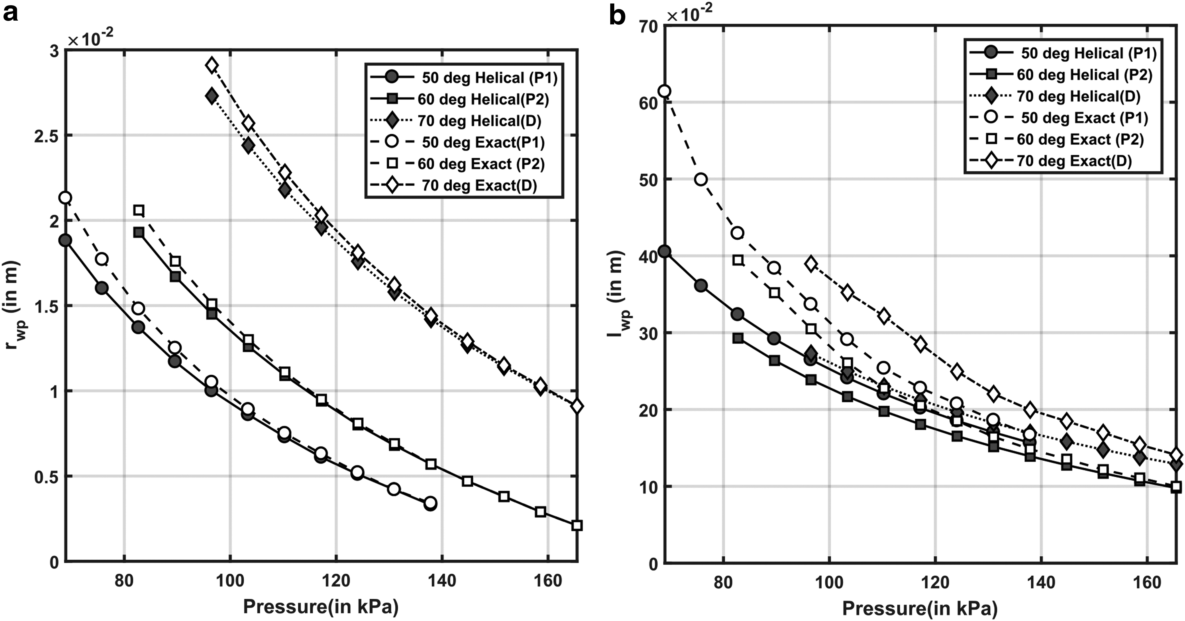
Comparison of the minimum
For each pressure value, the minimum length of the FREE required to complete one turn according to Equation (19) is plotted in Figure 7b. It is seen that workpiece with smaller lengths can be gripped at higher pressures. Furthermore, the inclusion of gravity leads to a 40% increase at most in the estimation of minimum FREE length at smaller pressures. To summarize, the pure helical approximation may be good enough for estimating the workpiece radius but yields large errors in estimating the workpiece lengths. This has implications in the design, as will be seen in the next sections.
Experimental Validation
We validate our proposed analysis for estimating the exact shape of the spiral FREE and the radius of the objects that can be gripped in this section on two prototypes. Table 1 gives the parameters used for both the prototypes.
Parameters for Prototypes Used for Validation
Exact shape estimation
To verify the shape predicted by the Cosserat model, the spiral actuator is fixed at one end and is actuated to different pressures in steps of 13.7895 kPa (2 psi). The shape of the spiral actuator is obtained using a Microscribe 3D digitizer as shown in Figure 8a and b.

Experimental setup and validation of exact model.
The experimental and analytical final shapes of the actuator at 55 kPa (8 psi) and 110 kPa (16 psi) is shown in Figure 8c–f with both XZ and YZ views. The end point of the analytical shape matches the experimental shape with an average error of 5.1% of total length for first prototype (P1) and 6.1% of total length for prototype 2 (P2). These measures are reasonable when compared to those reported in literature for similar models. 23 This validates that the Cosserat model gives a reasonable estimate for the final shape of the FREEs.
Gripping of objects of different radius
A set of 3D printed cylinders with radius 10, 12, 14, 15, 20 and 25 mm are used, and the range of pressures at which successful gripping occurs (till curling is observed) is recorded. Figure 9 shows the analytically estimated pressures from the Cosserat analysis and experimentally obtained pressure ranges for different prototypes. For prototype 2 our prediction is reasonable, whereas for prototype 1 the analysis predicts in the lower range of pressures as observed in Figure 9.

Comparison of estimated pressure for perfect grasp using the analytical mechanics-based model and experiments for different workpiece radius. The experimental estimates are given as a range of pressures between onset of perfect grasp and beginning of curling, all identified visually.
Guidelines for Design
In this section, a design framework is presented for selecting the geometry variables of a spiral FREE to grip different workpiece objects within a given radii range denoted by
In this example, we are interested in designing a FREE-based spiral gripper that can successfully grip a range of objects between a tubelight and a PVC pipe whose parameters are given in Table 2. In other words, any regular or irregular object whose size lies within the radius and length ranges of these two objects will be gripped.
Parameters of the Workpiece Objects That Are Required to Be Gripped
1. Step 1: Choose the radius of the FREE actuator (
2. Step 2: Evaluate minimum and maximum workpiece radius ratios (
3. Step 3: Choose the appropriate fiber angle
4. Step 4: Select the FREE length. The FREE length is chosen on the consideration that at least one complete turn can be obtained while gripping a workpiece of maximum radius and length. It can then successfully grip smaller objects by wrapping with more than one turn. First, we will design the FREE length for the maximum radius requirement, and in the next step check to see if it satisfies the length requirement. The FREE length is thus determined by the
5. Step 5: Check if ratio of length of workpiece to actuator radius is satisfied from Figure 5b. For the range of stretch ratios
6. Step 6: Exact correction. The previous design steps are based on the helical assumption. Influence of gravity changes the radius range and the workpiece lengths that can be gripped. For our example from the helical assumption we chose the actuator length to be 361 mm. We thus estimated the change in
7. Step 7: Exact design space obtained. Now the parameters of the actuator are decided, so it is fabricated and material properties are obtained (in Appendix A2). Finally the pressure versus object radius is obtained, and the pressure at which the actuator grips the objects is determined and is shown in Figure 10a.

Comparing the analytical and experimental pressures to grip the specified objects.
Strains and Minimum Workpiece Length Needed When 70° Actuator Is Selected
Figure 10b and c shows the gripping of the tubelight and the PVC pipe by the designed prototype. Figure 10d shows that the prototype can also grip a cylinder of varying radius that varies between the radius of tubelight (11 mm) and PVC pipe (30 mm).
Discussion
Design of spiral FREEs as grippers involve selecting the fiber angle at the local material scale and mapping it to the global deformation, which determines the size of the workpiece objects that can be successfully handled. Though the effect of gravity on the deformation pattern is considerable, FREE grippers can be successfully designed using pure helical assumptions alone, if sufficient margins are accounted for during the process, such as making the FREE length longer than needed as in Step 6. Furthermore, to accommodate the change in spiral radius of the FREE due of gravity, Steps 2 and 3 can be reworked with slightly larger workpiece radii ranges (i.e., larger
Conclusions
Gripping action obtained by spirally twirling the gripper around an object can be helpful for handling long, slender, and irregular shaped objects. Although several recent publications have alluded to the usefulness of spiral configuration using fiber-reinforced pneumatic actuators in grasping underwater objects, for snake-like motion and for navigation in a pipe, there has been no formal attempt in investigating the mechanism and formulating guidelines to systematically design them. In this paper, we investigate a spiral configuration of pneumatically actuated FREEs with two families of fibers that are asymmetrically oriented.
The most significant contribution of the paper is in proposing two simplified mechanics-based models to analyze and design the FREE-based fiber gripper. The first model considers the deformed profile to be an ideal helix, while the second considers a Cosserat rod model with acting gravity forces. The Cosserat model predicts the deformation with an error less than 8% of the actuator length. The two models can help inform the design of the FREE gripper—the fiber angles, cylinder radius, and length—based on the range of workpiece objects to be manipulated. This has been presented in the paper through systematic guidelines. These reduced-order models are important because alternative models such as an extensive finite element analysis can be time consuming and numerically expensive. We have demonstrated the efficacy of the reduced-order model through experimental validation by successfully designing a FREE gripper for grasping a range of slender objects ranging from a tubelight to a larger PVC pipe.
Though successful, there are some limitations of the work presented that can be mitigated in future work. For example, the modeling and design guidelines are limited to a unique class of FREEs with two families of fibers and a single fiber. Out of these, one fiber family is circumferential (α = 90°), the other family
Footnotes
Acknowledgment
This work was supported by NSF CMMI-1454276.
Author Disclosure Statement
No competing financial interests exist.
Appendix A1. Mechanics-Based Modeling of Spiral Fiber Reinforced Elastomeric Enclosures Using Cosserat Rod Theory
In this section, we present the basic equations required to predict the deformed shape of Fiber Reinforced Elastomeric Enclosures (FREEs) under the action of external loads. These equations have been presented earlierA1–A4 to model long and slender members routinely used in robotics.
The FREE shape is characterized by its unstretched central axis curve shown in Figure A1a. The position of any point
where
From the force and moment balance equation and taking their derivative with respect to s, we can arrive at the following set of equations for a section of rod.A1–A4
where
where
From Equations (A1)–(A6) we can arrive at the following system of equations where we assume no body moments (
To estimate exact shape of actuator, a set of ordinary differential equations (in Eq (A7)) are solved as a boundary value problem. At
Appendix A2. Estimation of Material Properties
To obtain a relation between actuation pressure and extension parameter, we need to estimate the Mooney Rivlin constants C1 and C2 of the elastomer. We take a small section of the fabricated actuator with fiber angles
A value of
Appendix A3. Evaluation of \documentclass{aastex}\usepackage{amsbsy}\usepackage{amsfonts}\usepackage{amssymb}\usepackage{bm}\usepackage{mathrsfs}\usepackage{pifont}\usepackage{stmaryrd}\usepackage{textcomp}\usepackage{portland,xspace}\usepackage{amsmath,amsxtra}\usepackage{upgreek}\pagestyle{empty}\DeclareMathSizes{10}{9}{7}{6}\begin{document} $${ \theta _{end}}$$ \end{document}
Solving Equation (A7) provides the orientation information (
To estimate the orientation vector,