




Abstract
Abstract
This article presents Exo-Glove Poly (EGP) II, a soft wearable robot for the hand with a glove that is completely constructed of polymer materials and that operates through tendon-driven actuation for use in spinal cord injury (SCI). EGP II can restore the ability to pinch and grasp any object for people with SCI in daily life. The design of the glove allows it to be compact and extends the range of hand sizes that can fit. A passive thumb structure was developed to oppose the thumb for improved grasping. To increase the robustness of the glove, EGP II was designed to have a minimal number of components using a single material. A kinematic model of the system was used to optimize the design parameters of an antagonistic tendon routing system on a single actuator for various hand sizes and repeated actuations. Experiments were conducted on two subjects with SCI to verify the grasping performance of EGP II. EGP II has a compact glove and an actuation system that can be placed on a desk or wheelchair, with the weights of 104 g and 1.14 kg, respectively.
Introduction
T
Recently, soft materials have been used to develop compact soft wearable robots for hands. Using soft materials enables a jointless structure, which resolves the problem of aligning the joints of the human finger to a rigid hand exoskeleton,7–12 and enables soft wearable robots for hands to be compact and much easier to don and use.
Three actuation methods are commonly used when developing soft wearable robots for hands: pneumatic actuation, hydraulic actuation, and tendon-driven actuation. In pneumatically actuated robots13–19 and hydraulically actuated robots,20,21 polymers13–18,20,21 and fabrics 19 are used to design chambers that can generate finger bending motions. In these designs, the direction of inflation in the chamber is controlled to generate the target bending motion. The conventional solution is to design a bellows-shaped chamber, as shown in Yap et al.15,19 Alternatively, Polygerinos et al. 21 used strings embedded during the fabrication process to constrain the inflation direction of the chamber, and Exo-Glove PM 16 used a thin rigid structure to provide constraint. Pneumatic actuators and hydraulic actuators have advantages, including high compliance and low inherent stiffness. However, they are also potentially limited by issues, including leakage.
Tendon-driven robots17,22–28 generally use fabric-based materials for the body of the design (i.e., gloves).17,22,24–28 The actuation system mostly uses electric motors to generate tension through wires. To generate the target bending motion, the wire tension generated by the actuator is transmitted to the finger through a tendon path on the glove. Exo-Glove 22 used Teflon tubes, and GraspyGlove 24 used Velcro straps and a rigid plate to design tendon paths on a fabric glove. Although the friction along the tendon path causes loss in force transmission efficiency, this compact actuation system enables portable designs. In addition, the body, the wearing part, on the hand can be more compact compared with the body of pneumatically actuated robots.
When developing these kinds of tendon-driven soft wearable robots, consideration should be given to robotic and ergonomic performance. Robotic performance includes target motion generation through tendon path design, adaptation to various hand sizes, robust design for repeated actuation, etc, whereas ergonomic performance includes hygiene, safety, wearability, compactness, etc.
Among these considerations, Exo-Glove Poly (EGP)
23
focused on generating grasping motion, specifically the index and middle fingers, and was tested on healthy subjects. EGP used a waterproof polymer with rigid components instead of fabrics to overcome hygiene issues. However, EGP has several limitations specific to robotic performance:
The manual assembly process of various components, a particular example being the Teflon tubes of the glove, created robustness issues after repeated actuations, and was not suitable for consistent manufacturing. The thumb design of the glove did not adapt well to different hand sizes, and the flexion and extension motions of the thumb were not favorable for grasping. The three-dimensional (3D)-printed rigid tendon anchoring support (TAS) could not adapt to different hand sizes and was a potential safety hazard because of concentrated application of pressure to the contact areas between the TAS and the hand. The unoptimized antagonistic tendon-driven actuation system had sometimes created too much slack, or it became constrained by positional singularities, depending on different hand sizes. Too much slack in the actuation system increased the single operation time, and caused failure in the actuation system during repeated actuations. The occurrence of positional singularities is directly related to hand safety issues.
In this article we present EGP II (Fig. 1), a polymer-based soft wearable robot for the hand. EGP II uses tendon-driven actuation to help SCI patients with flaccid hands but no hand mobility. EGP II focused on improving aforementioned limitations on the robotic performance of EGP. The major improvements of EGP II are as follows:

EGP consists of a soft polymer glove, wire sheaths, and an actuation system and a freestanding intention button that users press to actuate the glove. EGP, Exo-Glove Poly.
A reduced number of components, usage of no rigid materials, and a drastically reduced need for manual post-assembly processes improved the robustness of the glove and enabled consistent manufacturing.
The passive thumb structure (PTS) was developed to fit all thumb sizes and for opposing the thumb to create favorable grasping; additionally it reduced the number of necessary actuators from 2 to 1.
The new polymer TAS softly adapts to different hand sizes, and improves the distribution of forces between the TAS and the hand.
The design parameters of the actuation system were optimized by understanding the behavior of the slack in the antagonistic tendon-driven actuation system based on a kinematic model. This reduced the amount of slack during actuation and prevented the robot from reaching the positional singularities of different hand sizes.
The performance of EGP II was verified by performing object-grasping experiments with two SCI patients, and underactuation was tested with subjects who had no hand movement deficits.
Design and Features
In this section, we present the design and features of EGP II. To increase the robustness of the glove, its components were reduced from 10 23 to 4 (Fig. 2), and certain components, such as the tendon paths, were embedded during manufacturing. EGP II uses the same underactuation mechanism and dual-slack enabling mechanism as Exo-Glove 22 and EGP. 23 The glove was designed to allow the robot to adapt to different hand sizes, including differences in finger, palm, and wrist size. To increase the adaptability of the robot's thumb and its ability to grasp by forming an opposition posture, a PTS was developed. The PTS allowed the number of actuators to be reduced to one and improved the compactness of the actuation system. A new TAS design was applied to improve safety.

Component parts of EGP.
EGP II consists of a glove, sheaths, an actuation system, and a button. Figure 2 shows EGP II glove components before assembly. The glove consists of a body and a PTS. To complete the glove, two thimbles must be attached to the body. The sheaths cover the actuation wires from the point at which they exit the actuator to the body of the glove and help transmit the wire tension to the glove. Like Exo-Glove and EGP, EGP II separates the actuation system from the glove to minimize the weight the user must bear. The actuation system is designed, so that it can be placed on a wheelchair or a desk. The button is used to detect the intention of the user.
Body
The body of EGP II is designed to flex and extend the index and middle fingers with a single actuator. Flexion of the index and middle fingers is driven by a single wire using the underactuation mechanism, while extension is driven by two separate wires as in previous versions.22,23 The body consists of finger bodies, straps, a dorsal body, a volar body, a palm strap, and TASs (Fig. 3).

Components of the EGP glove.
The finger body connects the dorsal body and a thimble, and the straps stretch out from the finger body. The straps are placed on the side of the finger body and play an important role in determining the length of the flexion moment arm for each joint.
The finger bodies and straps were designed to accommodate a wide range of hand sizes, especially with regard to finger length and thickness. Exo-Glove used a stretchable fabric glove to accommodate various hand sizes, but its straps, which were designed to define the flexion wire path and the moment arm length, were made of nonstretchable fabrics. In addition, Exo-Glove and EGP had only two finger straps, each located at the center of the proximal and middle phalanges. With this design, if the glove is configured for one hand size and is then placed on a hand of another size, the placement of the finger straps must be reconfigured to ensure that they correctly align on the phalanges. If this is not done, an appropriate torque will not be applied on all joints. To avoid the problems in EGP, 23 EGP II modified the design of the finger body to be composed of only a diamond-shaped pattern design; this pattern starts from the thimble to the dorsal body. The design of the finger straps was modified to have an increased number of thinner straps that employ less compliant materials.
We chose to make EGP II from a single polymer (KE-1300T; Shin-Etsu Chemical Co., Ltd.) because, unlike fabrics, it can be difficult to bond polymers to other materials. The selected polymer has a low strain rate to maintain the moment arm, while the required stretchable ability to adapt to different finger sizes is achieved by pattern design. As shown in Figure 3, the finger body has a modified diamond pattern design with respect to the design of EGP, which enables it to easily stretch. The strap is subdivided and placed on the diamond-shaped corner of the finger body.
The dorsal body and the volar body work as a hub that connects other components and forms tendon paths. The dorsal body is positioned on the back of the hand and connects the finger body, palm strap, and TAS. The dorsal body forms an extension wire path for the index and middle fingers through the TAS and the finger body. A magnet is embedded to allow the palm strap to be fixed. The volar body is positioned on the palm, and indirectly connects to the palm strap and the TAS through a flexion wire through the TAS. Unlike the dorsal body, the volar body has four flexion wire paths, which together form the underactuation wire path as in EGP. The volar body was designed to avoid disturbing the movement of the thumb. In addition, these relatively large bodies, compared with other components, are designed to minimize the area of skin that the robot covers, to ensure good ventilation of the skin. Both the extension and the flexion wire paths through the body were designed to minimize friction. It is important to ensure that the glove's components are thin enough to allow for dexterous grasping, while also being strong enough to withstand tensioning of the wires.
The palm strap was designed to accommodate different palm girths. Because the volar body and the dorsal body form tendon paths, it is important for these bodies to align with the index and middle fingers. However, owing to differences in palm girth for each person, the relative position of the two bodies and the length between them must be adjustable. To satisfy these criteria as well as to increase wearability, the palm strap was designed to be stretchable using the same design as EGP, and magnets were embedded for easy attachment and detachment. The magnet design has made wearing EGP II easier and faster than EGP for patients who cannot control their fingers.
The TAS of EGP II anchors the glove to the hand, which allows for efficient transmission of the wire tension to the fingertips. The requirement of the TAS is to fix the glove to the hand against the force acting in the direction of the fingertips. Other requirements include evenly distributing the force acting on the hand to minimize pressure on the skin and preventing the tendon path from being affected by wrist movements. In EGP, these requirements were not met due to the rigidity of the TAS, and the tendon path connection between the soft polymer body and the rigid TAS. The weak Velcro connections between the body and the TAS created kinks along the tendon path during actuation. To resolve these issues and meet the design requirements of EGP II, the TAS was fabricated from polymer and using a watch strap design, as shown in Figure 3. Also, two TASs were used to better fix the dorsal and volar bodies and to efficiently transmit force. The polymer TAS adapts well to the wrist shapes of different people, and it distributes pressure evenly because the area of contact with the skin is wide. Because the tendon path is secured by the polymer and Teflon tubes, the length of the tendon path does not change even when the TAS is fixed to the wrist, and thus movements of the wrist do not affect it. Also, moving the TAS to the wrist prevents it from interfering with the movement of the thumb.
Thimble
In EGP II, the thimble (Fig. 3) plays three important roles: first, it anchors EGP II to the fingertips. Securely fixing the thimble to a fingertip allows it to deliver torque to the finger joints when tension is delivered along the flexion and extension wires. Because the thimble is made of compliant material, it should be designed to wrap around the fingertip, so that the thimble is fixed without being twisted or pushed.
The second role of the thimble is to form wire paths for flexion and extension. Because the thimble is compliant, the flexion wire path needs to go around the dorsal side of the fingertip, and the extension wire path needs to go around the volar side of the fingertip to maximize force transmission to the fingertip and to prevent the thimble from tearing. In particular, to adaptively grasp any object using underactuation, the wire must be able to move along the flexion wire path in the thimble. A Teflon tube was embedded in the tendon path of the thimble to minimize wire friction.
The third and final role of the thimble is to help users to grasp objects by increasing friction between the object and the hand according to the properties of the polymer from which the thimble is made. To perform this role, the thickness of the thimble should be minimized, because a thick thimble would interfere with grasping. The thimble was fabricated separately from the body both to ensure that it could meet the criteria described above and because of its complex 3D shell design that includes undercutting and Teflon tube embedding.
Passive thumb structure
EGP II uses a PTS without an actuator (Fig. 3). Using the PTS means that EGP II can oppose the thumb instead of simply flexing the thumb, as was the case for Exo-Glove and EGP. The PTS is a thin layer of polymer embedded with thermoplastic (Orfit Classic; Orfit Inc.). Because thermoplastic is easy to reshape, it is suitable for use to adapt to the thumb size, which varies among users. However, thermoplastic cannot be repeatedly reshaped without causing plastic deformation. To enable EGP II (1) to be effective in settings where multiple people will use it in sequence, such as a hospital rehabilitation department or (2) to continuously adapt to the shape and size of a long-term user's hand, attention must be paid to minimizing the limitations of the thermoplastic in the PTS. We found that coating a thin layer of polymer over the thermoplastic allowed the PTS to be repeatedly reshaped. Because the thermoplastic is perforated, the polymer coating seeps into the pores, and this impregnation process prevents plastic deformation of the thermoplastic and increases its reusability. Other advantage of the polymer coating is that it increases friction between the PTS and a grasped object.
Other components
Other components of EGP II are sheaths, a button, and an actuation system (Fig. 4). Wires from the actuation system are connected to the glove through sheaths consisting of tension springs. Tension springs were chosen for this purpose because the sheaths must be flexible and maintain absolute length even when compression forces are applied. A push button is connected to the actuation system for intention detection.

The actuation system consists of a dual-slack enabling actuator,29,30 a custom-made electric board with digital signal processor (TMS320F2808; Texas Instruments Inc.), and a four-cell lithium-ion battery (12V, 2.6Ah). In EGP II, an actuator (IG-32GM 03TYPE, 12V, 7W; D&J WITH Co., Ltd.) with a planetary gearhead with a 35:1 reduction ratio was used instead of the 20W actuator used in EGP. 23 By reducing friction along the tendon path with the new TAS design, EGP II allows the use of a lower power actuator. The actuation system was designed to be placed on a table or the back of a wheelchair, and it measures 125 × 75 × 138 mm and weighs <1.15 kg. Using a dual-slack enabling actuator allows both the flexion and the extension wires for the index and middle fingers to be antagonistically bound to a single pulley.
Kinematic Model of EGP II
This section presents a simplified kinematic model of EGP II consisting of a single finger from the glove (Fig. 5). The model increases the robustness of the actuation system by optimizing the pulley dimensions and actuator slack. The kinematic model was used to predict the actuation lengths required to flex and extend the finger. Meanwhile, the length of the actuated flexion and extension wires can be estimated from the actuator by the amount of actuator rotation and pulley dimensions. The relation between the estimated required wire lengths from the kinematic model and the actuator was used to optimize the dimensions of the pulley and the amount of slack of the actuator.

The one-finger kinematic model of EGP.
Actuator slack is necessary to accommodate the actuation wire lengths that are required for different hand sizes, because the flexion and extension wires are antagonistically connected to a single motor. In EGP II, the slack is in the extension wire (it could also have been placed in the flexion wire). A properly designed pulley and slack in the extension wire allows EGP II to adapt to different hand sizes, allowing the hand to fully extend the fingers and preventing the glove from meeting singular points at which the hand cannot flex. In addition, to reduce operation time, which is directly related to actuated wire length, the wire length required to fully flex and extend the finger needs to be minimized. This also improves the robustness of the actuation system by reducing the amount of wire wound around the pulley. The length from the actuator to the dorsal body or the volar body does not change owing to the sheath and the Teflon tubes embedded in the bodies. Therefore, the only possible region where the distance of the wire path can change is between the dorsal/volar body and the thimble.
In EGP II, a single flexion wire travels through the underactuation tendon routing path of the index and middle fingers, and two separate extension wires are connected to each finger. The actuator must pull the flexion wire about twice as much as the extension wire. Without a properly designed pulley, the working length of the wire could be too long or too short. However, since the length of the wire that needs to be driven is increased by the amount of slack in the wire, it is important to minimize the amount of slack to keep the single operation time reasonably fast.
Three goals drive the choice of pulley dimensions and the amount of slack in the extension wire: first, the actuated flexion wire lengths in all postures should always be greater than the actuated extension wire lengths, to prevent the occurrence of singular points in all cases of flexion and extension. Second, the slack in the extension wire should be minimized to minimize single operation time. Third, it is important to properly design the ratio of the pulley radius to the ratio of required flexion and extension wire lengths to actuate fingers. We performed kinematic model analysis to design an actuation system that achieves these three goals.
The kinematic model makes the following assumptions: the phalanges are rectangular, and the joints are placed on the center line of each phalange. The strap of EGP II is rigid, and the first strap is located at the center of the proximal phalange. The thimble is attached to the distal phalange, and the remaining straps are evenly spaced between the first strap and the thimble. The two end points of the flexion wire are fixed to the palmar body and the thimble, and the flexion wire path is determined by the straps. Meanwhile, since the extension wire passes along the back of the hand, the extended distance between the phalanges is taken to be an arc with a diameter equal to the thickness of the finger. As the finger changes to a specific posture, the increased or decreased wire path length means that the actuated wire length must change as required to make the posture. Important parameters for the model are shown in Figure 5 and listed in Table 1.
Parameters for Kinematic Model
MCP, metacarpophalangeal; PIP, proximal interphalangeal; DIP, distal interphalangeal.
In the kinematic model, the x-axis is aligned to the midline of the metacarpal joint and the y-axis is placed at the end of the volar body. The unit vector ui and the vector vi define the kinematics of each phalange. Ai is the length of each phalange, and i = 1,2,3,4 corresponds to the metacarpal, proximal, intermediate, and distal phalanges, respectively. θj defines the joint angle, Rj is the rotation matrix for each joint, and j = 1, 2, 3 corresponds to the metacarpophalangeal (MCP), proximal interphalangeal (PIP), and distal interphalangeal (DIP) joints. Vectors are defined as follows:
In this model, straps are placed on the finger. p1 is the end point of the volar body, p2 to p5 are the end points of the straps, and p6 is the end point of the thimble. dk is the distance from p2 to pk containing in-between p points, where k = 3, 4, 5, and p is defined as follows:
where t is the half of the finger thickness and s is the distance from center line of phalange to strap end. The distance from p1 to p6 defines the flexion wire path, and thereby the change in distance between p defines the required flexion wire length for flexion. On the contrary, the required extension wire path is defined as sum of change in arc length of each joint, as previously mentioned in the kinematic model assumptions. Thus, the required flexion and extension wire lengths work in accordance with assumptions and notations that are defined as follows:
where FlKM and ExKM are the required wire lengths to move finger to a particular posture in the kinematic model. Given that EGP II uses an underactuation mechanism for flexion, the actual actuated flexion wire length should double for each finger. However, the flexion wire and the extension wires are antagonistically connected to an actuator, so that two actuation wires are pushed or pulled proportionally. The actuated flexion and extension wire lengths in the actuator model are defined as follows:
where FlAM and ExAM are the actuated wire lengths needed for flexion and extension in the actuator model, IS refers to the initial slack of the extension wire, rf and re are the flexion and extension pulley radii, and ϕm is the actuated actuator angle. When building the EGP II, the flexion wire is first connected to the pulley, then the extension wires from the pulley are connected loosely to the thimble. Therefore, the required flexion wire length in the kinematic model (2FlKM) is equal to the actuated flexion wire length in the actuator model (FlAM).
The purpose of these models is to optimize re/rf and IS. EGP II will have too much slack or will encounter singular points during actuation without a proper ratio between rf and re. Minimizing slack is important because it is directly related to actuation time in a single stroke. Therefore, two conditions must be met to optimize the ratio of the pulley radius and the initial slack. The first condition is that ExAM must always be greater than ExKM to avoid singular points during actuation. The second condition is to minimize the amount of slack during actuation, which is ExAM minus ExKM. These two conditions can be expressed as follows:
To find the optimal re/rf and IS, the amount of slack during actuation (ExAM − ExKM) is plotted against re/rf and IS (Fig. 6). The kinematic model assumes that the MCP, PIP, and DIP joint angles represent actual grasping while using EGP II. The finger joint angles were measured for a specific grasping case (using motion analysis software, ProAnalyst), while the human hand was actuated using EGP II, and Figure 7a lists the recorded joint angles. The amount of slack is calculated for two subjects with different hand size parameters. Figure 6a and b shows the results for each subject, and Figure 6c shows the combined results for both subjects. The navy blue region in Figure 6 (marked “N/A”) indicates the presence of singular points, and the boundary of this area indicates the least amount of slack during actuation. The red dot in Figure 6c shows the selected actuation system design of EGP II. The selected re/rf and IS are 0.417 and 0 mm, respectively. Based on re/rf, the maximum pulley radius for extension and flexion that can fit into the dual-slack enabling actuator was chosen, which were 2.5 and 6 mm, respectively.

The amount of slack observed with varying pulley radius ratios and initial slack in the extension wire, based on the kinematic model.

Results of the verification experiment for subject 1.
To verify the actuation system design, the measured finger joint angles from Figure 7a were used. Figure 7b shows the estimated result of the actuated wire length based on the kinematic model using recorded joint angles (solid line) and the actuator model using recorded actuator angles (dashed lines). Although EGP II was manufactured with ∼0 mm of initial slack, still, some slack exists due to a difference in hand sizes and the compliance of the glove.
In Figure 7b, the first gray region (0–0.2 s) depicts no motion of the finger (solid line) while the wire was actuated during flexion and extension (dashed lines). Therefore, the difference between the dashed line and the solid line at the end of the first gray region can be defined as the initial slack of the robot, ∼25 mm in the flexion wire and 10 mm in the extension wire. After the initial slack region, the finger will begin to either flex or extend. While the finger is moving (0.2–0.65 s), it is important to note that the estimated actuated wire length, based on the kinematic model, and the measured actuated wire length represent similar slopes. Meaning, the pulley radius parameters are well defined. The second gray region (0.65–0.9 s) shows that the actuator continued to pull the flexion wire even after the finger was almost fully flexed. There are two reasons why the difference between the estimated actuated wire length, based on the kinematic model (dashed lines), and the actuated wire length from the actuator (solid line) increased. The compliance of EGP II and the finger was not included in the kinematic model. After the finger was fully flexed, the compliance of EGP II and the finger changed the tendon path, so that the actuator could continuously pull the wire. The second reason is the elastic characteristic of the wire. In this region, the wire tension increases, and the contact force between the thumb and index finger increases. In Figure 7b, it should be noticed that the actuated length, from the actuator model (dashed lines), is always greater than the actuated length, from the kinematic model (solid line), to 0.9 s. This satisfies the first condition (Eq. 16) of the model.
Performance
This section describes experiments conducted to verify the general performance of EGP II and its underactuation mechanism. All experiments were conducted with two subjects with different hand sizes. The underactuation experiments were performed with two healthy subjects. All other experiments were performed with two subjects who had an SCI at C6 that left them with no hand mobility. Both SCI subjects had flaccid hands, and other parts of the upper limb, including the wrist, were fully functional. The experiments were conducted under an approved IRB protocol (IRB No. 1801/001-005). All participants provided written, informed consent according to the approved IRB consent process.
Grasping performance
To quantitatively verify grasping performance, an experiment was designed to determine how well subjects wearing EGP II can grasp three objects of different sizes and shapes. A box, a cylinder, and a sphere were selected because these shapes are commonly encountered in daily life. The thickness of the boxes and diameters of the cylindrical objects ranged from 10 to 100 mm, and the diameters of the spherical objects ranged from 30 to 90 mm in 10 mm increments. To rule out friction difference between the objects and the EGP II or hand, all objects were created with the same material poly lactic acid using a 3D printer (Ultimaker2; Ultimaker B.V., The Netherlands). The experimental setup consisted of a two-platform stage. A load cell (333FB Cell; Ktoyo Co., Ltd., Korea) was fixed to the bottom platform, and objects to be grasped were placed on the top platform. A hole was drilled at the center of the top platform to permit objects to be connected to the load cell by strings. Figure 8 shows the experimental setup and a sample of the objects used.
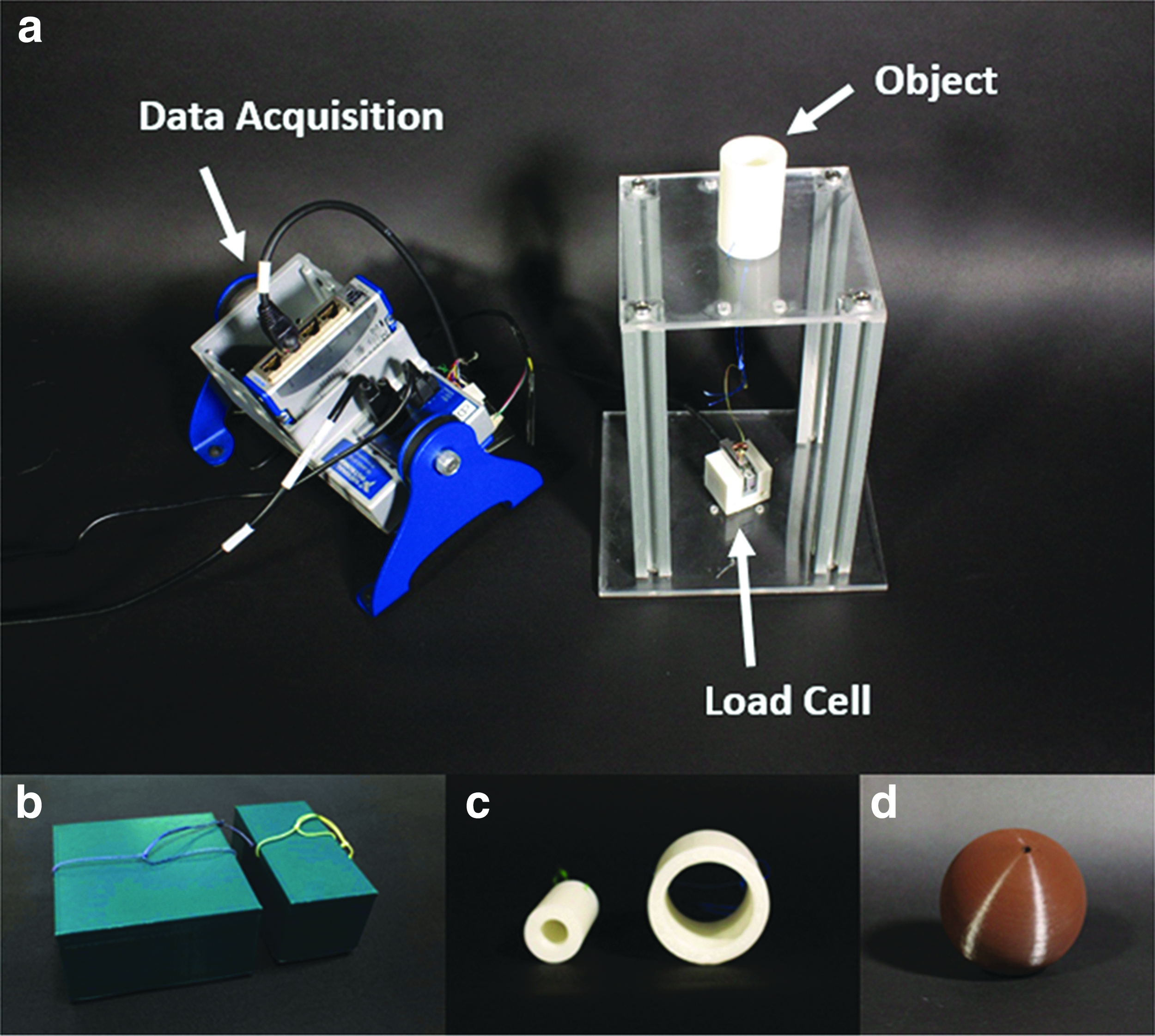
Experimental setup and a sample of the objects used.
Subjects were instructed to grasp the object on the top platform and raise it until it fell from their hands. The experiment was designed to measure how firmly EGP II can grasp each shape and size of the object. To compare and verify the effect of wearing EGP II, each grasping task was conducted three times with each object with and without EGP II, and the maximum force required to grasp each object was recorded and averaged. Figure 9 shows the results of the experiment.

Results for the grasping performance experiment with the two SCI subjects.
Results without EGP II showed some subjects' grasping ability using tenodesis and the friction between the fingers and the objects, even though the subjects had no hand mobility. The results showed that both subjects had a better grasp when wearing EGP II. The hand size of subject 1 was not large enough to permit the subject to grasp the 100 mm diameter cylinder either with or without EGP II. The hand size of subject 2 was large enough to permit the subject to grasp the 100 mm diameter cylinder, but the subject experienced difficulty grasping the 10 mm diameter cylinder both with and without EGP II. The results of the box-grasping trials were similar for both subjects, but their results differed in the cylinder- and sphere-grasping trials. The main reason for these results was the PTS of EGP II. The PTS was not designed to entirely cover the thumb, and if the PTS touched an object during a grasping trial, the resulting increase in friction on the object increased the grasping force exerted on the object. For subject 1, PTS was always contacting the objects. On the contrary, for subject 2, PTS was only contacting the cylindrical objects with diameter from 50 to 60 mm and the spherical objects with diameter from 60 to 80 mm.
Underactuation performance
The experimental setup used to evaluate the underactuation performance of EGP II consisted of two pressable buttons mounted on a 3D-printed box (Ultimaker2; Ultimaker B.V.) and connected to two load cells (333FB Cell; Ktoyo Co., Ltd.) within the box (Fig. 10). Subjects were asked to use their index and middle fingers to depress the buttons. The buttons could be depressed from 0 to 20 mm in increments of 10 mm. The load cells were used to measure the pinching force exerted by the index and middle fingers during underactuation of EGP II.

Experimental setup for measuring underactuation performance.
Underactuation experiments were initially tested on subjects with SCI, but they were not able to properly push the bottom load cell with middle finger because the middle finger trajectory while underactuation varied depending on subjects. Therefore, the experiments were conducted on healthy subjects. Underactuation experiments were conducted two times for each subject for each gap difference. The results are shown in Figure 11.

Results of underactuation performance tests on two healthy subjects.
The expected results for underactuation performance are that each finger generates evenly distributed force and as the gap increases, the contact time difference between the index and middle fingers increases. The result shows that the pinching force generated by the index and middle fingers is not exactly the same. The main cause of the difference is friction along the underactuation tendon routing paths. However, by using Teflon tubes on all tendon routing paths to minimize friction forces, we were able to increase underactuation performance by decreasing the force difference to <30% maximum. Both subjects had contact time difference between the index and middle fingers of ∼0.25 s for each 10 mm gap. Since EGP II pulls the predefined actuation wire lengths unconditionally without any sensory feedback, the total pinching force decreases as the gap between the two load cells increases.
Wrap grasp and pressure distribution
The wrap grasp is a commonly used grasping motion. To measure force distribution on objects being held with a wrap-grasping motion, an experiment was conducted using a mat-type pressure sensor (160 mm 2 × 160 mm 2 sensor; Pliance Hand Mat Sensor, Novel Inc., Germany). Experimental setup is shown in Figure 12a. Each subject, wearing EGP II, was instructed to grasp three cylindrical objects with diameters of 50, 75, and 100 mm (Fig. 12b). The results are shown in Figure 13.

Experimental setup for wrap grasp on cylindrical object with diameter of 75 mm using mat-type pressure sensor.

Pressure distribution measurements obtained during wrap grasp experiments with two SCI subjects.
As indicated in the figure, most force was generated on the fingers. The sum of all the normal forces generated during grasping was 10.3N, 9.3N, and 8.9N for subject 1 and 10.6N, 8.4N, and 8N for subject 2 for the 50, 75, and 100 mm objects, respectively. For both subjects, the total normal forces acting on the objects tended to decrease as object diameter increased. The index and middle fingers were expected to exert similar forces on the objects. When grasping a 75 mm object, both subjects held their palm in contact with the object. However, in some cases, the subjects unintentionally twisted their hands to improve their grasp on an object (the habit of using tenodesis when grasping), and this generated uneven forces.
Tenodesis grasp is a passive natural mechanism that uses wrist extension to flex the fingers. Since the length of the tendons from the fingers to the arm does not change, the extension of the wrist causes passive finger flexion and creates weak grasping motions. SCI patients who have lost hand mobility commonly use tenodesis grasp in their daily lives to perform basic functions. With the current design of EGP II, it was impossible to restrict tenodesis grasp during experiments.
Grasping variety of real-world objects
The previous grasping performance experiments demonstrated that EGP II can be used to grasp a variety of differently shaped objects thanks to its underactuation mechanism. In this experiment, the subjects were instructed to grasp four different objects: (1) a small box, (2) a banana, (3) a baseball, and (4) a spray bottle (Fig. 14). The first three objects were selected to represent objects with a box, a cylindrical, and a spherical shape, respectively. The spray bottle was selected to demonstrate the underactuation performance of EGP II. The subjects were able to successfully grasp all four objects. Figure 14 shows photographs of subjects grasping the objects during the first trial.

Photographs demonstrating two SCI subjects grasping objects of various shapes with the assistance of the underactuating EGP.
Discussion
Recently, various soft wearable hand robots were developed to assist daily living and rehabilitation services for the disabled people who have lost hand mobility.13–28 However, to use wearable hand robots in daily living activities, the robot has to be portable and hygienic. Fabric-based soft wearable robots 13 have advantages in ventilation and have a higher tensile strength compared with their polymer counterparts. These robots, however, are less hygienic making them difficult to implement for daily tasks and in hospital settings due to concerns with infection or the passing of harmful pathogens. 23 Furthermore, previous studies have tried to handle positional control issues in tendon-driven wearable hand robots by focusing on actuation systems12,29 or the kinematic models of these robots. 20 However, these studies were limited to systems that implement antagonistic tendon-driven actuation.
In this article we present EGP II, a soft wearable hand-assist robot with a glove that is completely constructed of polymer materials using tendon-driven actuation. EGP II is developed for SCI patients who have lost their hand mobility but have full functionality in their other upper extremities. While EGP II inherited the underactuation mechanism and the dual-slack enabling mechanism used in Exo-Glove and EGP, EGP II focused on resolving the issues that affected the robotic performance of EGP.
The design of tendon paths for soft wearable robots that use tendon-driven actuation is essential.22–25 It is not only critical to the creation of desired motions, but it also minimizes friction and fatigue due to repeated actuations. To minimize friction, it is important to use a material with a low coefficient of friction and to reduce the curvature of tendon paths. The friction forces generated by the tension are concentrated along the curvatures of the tendon paths that straighten the wire paths. These forces reduce the robustness of the wire paths. The body of the glove must be thin for compactness but strong enough to endure wire tension. However, the manually assembled Teflon tubes for EGP were not able to withstand wire tension after repeated actuations, resulting in delamination from the polymer body. Furthermore, the Teflon tubes that connect the soft body to the rigid TAS had high curvatures, causing excessive friction along the tendon paths. In EGP II, by embedding Teflon tubes during the manufacturing process, the manual postassembly work for the tendon paths was removed. This increased the wire tension that the tendon paths could endure. In addition, the polymer TAS reduced the friction by forming smooth tendon paths.
Adapting to different body sizes is an important development issue for soft wearable robots, except in custom-user cases. Even with an adaptable glove design, EGP II cannot adapt to all different hand sizes. Among EGP II's various hand parameters, influential parameters were finger length, finger thickness, palm girth, and wrist circumference. Considering these factors, to improve the adaptability of the glove to different hand sizes, new design features have been proposed, including straps, a PTS, and the TAS. Eventually, to customize EGP II, we believe that combining an adaptable design with user-tailored methods currently used in commercialized products18,26 is necessary.
When using an antagonistic tendon-driven actuation system for soft wearable robots, the required wire lengths to generate the two different motions respectively change. Due to the difference in the required wire lengths, without the proper design of an actuation system, the wires would be too loose or too short to generate the full motions, resulting in robustness and safety issues. To resolve the issues present in EGP, 23 a kinematic model has been proposed to minimize the slack during actuation, by estimating the optimal wire lengths of the flexion and extension wires that are antagonistically bounded to the pulley. The pulley radius of the flexion and extension wires and the initial slack was optimized based on a specific target hand motion, using two different hand sizes in the kinematic model. Optimized parameters of the actuation system can be changed depending on how the target range of hand size is defined. Therefore, the kinematic model, using two different hand sizes, cannot over-ride the slack during actuation for all different hand sizes. Nevertheless, the proposed kinematic model is presented as a methodology for optimizing the design parameters by understanding the slack during antagonistic tendon-driven actuation of wearable robots. The kinematic model can further be used to optimize the development of user-tailored tendon-driven robots. Moreover, the model has potential to be used to generate almost zero slack motion when two motors are used individually for flexion and extension.
Although the current research on EGP II has focused only on its use as a hand mobility assistance device, it could potentially be used for a variety of purposes in different settings, including multiuser environments such as hospitals. Waterproofing the robot could allow it to be used for activities such as dishwashing, tooth brushing, and showering. Making the glove from a transparent polymer also aids safety by allowing users to visually check their hand status, which is especially important for SCI patients who have lost sensory feedback from their hands.
However, three issues must be dealt with before EGP II can be applied for wider purposes: first, to allow EGP II to be used by patients other than SCI, finger joint stiffness must be considered. Differences in finger joint stiffness between MPC, PIP, and DIP joints will play an essential role in determining glove design parameters, including EGP II. Furthermore, changes in finger joint stiffness, caused by the development of spasticity over time, can possibly affect the design and performance of the robot. Second, embedding sensors to the glove of EGP II is important to increase the dexterity of grasping. Finally, designing a universally useful intention detection method would be necessary in two-handed applications of EGP II. Throughout the article, we have presented the issues and possible solutions that researchers can encounter when designing and actuating soft tendon-driven wearable robots. EGP II shows the potential of soft robotics technology in rehabilitation applications, and further research on soft materials and understanding the human kinematics will lead to entirely new applications.
Footnotes
Acknowledgments
This study was supported by the Translational Research Center for Rehabilitation Robots (Grant No. NRCTR-EX16001), National Rehabilitation Center, Ministry of Health and Welfare, Korea. This work was supported by the National Research Foundation of Korea (NRF) Grant funded by the Korean Government (MSIP) (Grant No. NRF-2016R1A5A1938472).
Author Disclosure Statement
No competing financial interests exist.