
Abstract
Abstract
This article proposes a bioinspired variable stiffness dielectric elastomer actuator (VSDEA) that is inspired by the leaf habit of monocots. The VSDEA is a fully flexible strip with a curved cross section and a tip dielectric elastomer minimum energy structure (DEMES). An arc fixture is used to clamp the strip that imitates the connection mode between the leaf and the cylindrical stem of the monocot. When applying voltage on the tip DEMES, the transverse curvature of the strip is changed, and then, the bending stiffness of the VSDEA can be tuned. Effects of applied voltage and important design parameters on the bending behavior of the VSDEA are experimentally studied in detail. The results show that the bending stiffness of the VSDEA approximately decreases linearly with the increase of applied voltage, which is very advantageous for stiffness control. The load capacity of the VSDEA is enhanced due to the bioinspired clamping mechanism and can be tuned by the applied voltage. It can also be found from the tested VSDEA prototypes that, when the applied voltage ranges from 0 V to 5.6 kV, the maximum relative stiffness and critical load changes reach about 71.8% and 75.6%, respectively. The maximum stiffness and critical load are, respectively, 157.8 N/m and 889.9 mN, which are two orders greater in magnitude than general DEMESs; as a result, this VSDEA can bear a payload 139 times its weight. It demonstrates that the bioinspired VSDEA can be useful for soft robots, vibration control, and morphing applications.
Introduction
The ability of actively changing in stiffness or impedance for structures and actuators is very significant in robots, vibration control, morphing applications, and so on.1–3 Especially, with the rapid proliferation of soft robots inspired by soft-bodied animals and made of intrinsically soft and/or extensible materials, the ability to vary stiffness can further enhance the capability and adaptability of soft robots and make them more powerful in handling unexpected interactions with unstructured environments or humans.4–8 Compared with the conventional rigid-bodied robots, the high deformability and compliance of soft robots enable them to exhibit great potential in health care, search and rescue, and cooperative human assistance. However, the inherent low stiffness of soft robots often limits them in some practical applications that require high stiffness to exert or sustain considerable forces. Variable stiffness is a promising solution to overcome the contradiction between maintaining sufficient compliance and maximizing load capacity. Some mechanically actuated variable stiffness mechanisms have been successfully exploited for building passively compliant, robust, and dexterous rigid robots. However, they tend to be complex, cumbersome, slow, and difficult to miniaturize, which are not suitable for soft robots. 1
Inspired by biological systems such as octopus arm, squid tentacles, elephant trunk, and tongues in general, as well as human lips and hands, many variable stiffness mechanisms have been proposed for developing soft robots with controllable stiffness. 9 Most of the mechanisms and methods are based on smart materials and structures, either performing as actuators or through tuning the material's modulus or viscosity, such as jamming, electrorheological (ER) or magnetorheological (MR) fluids, shape memory alloy (SMA) or shape memory polymer (SMP), low melting point alloy (LMPA), and dielectric elastomer (DE).9–12 Although these variable stiffness methods have proven effective in changing the stiffness and enhancing the load capacity of soft robots, there are still shortcomings toward the practical applications. For example, jamming requires auxiliary equipment such as pumps and valves and a substantial volume of granular material, making the design of a jamming system complicated and bulky; ER and MR fluids require external electric or magnetic field, which may easily be affected by environments and their high density restricts the operating volume; heat-sensitive function materials such as SMA, SMP, and LMPA require heating for phase transition, and thus, they are susceptible to ambient temperature and have high energy consumption and narrow operation band; the LMPA also has problems in leakage and stiffness control even if it can achieve a very large stiffness change.
DE, known as the artificial muscle, has garnered remarkable attention recently for its large strain, high energy density, fast response, and theoretically high electromechanical efficiency.13–24 A DE consists of an elastomeric dielectric film sandwiched between two compliant electrodes. When a voltage is applied across the electrodes, the resulting Maxwell stresses cause area expansion and thickness reduction of the film. Such an electrical actuation mechanism, together with the inherent passive compliance and damping characteristic of the material, has made DE an appealing alternative to develop actuators with controllable stiffness for robotic application. The relatively high-inducing voltage and small actuation force currently limit the use of DE material in real-life applications. However, recent developments in material, advanced manufacturing technology suggest solutions to these problems.25,26
Several variable stiffness dielectric elastomer actuators (VSDEAs) have been proposed for stiffness modulation by the actuation of DE. The reported VSDEAs demonstrate great advantages in low weight, compact configuration, fast response, silent operation, convenient control, large stiffness change, and load capacity, and they have been exploited in a variety of application fields, such as robotic leg, 27 rehabilitation device, 28 suspensions, 29 and soft gripper.12,30 A VSDEA, which combines a flexible strip with a dielectric elastomer actuator (DEA) in a dielectric elastomer minimum energy structure (DEMES), has been presented in our previous work. 31 The DEA induces an analog tuning of the transverse curvature of the strip, thus conveniently providing a voltage-controllable flexural rigidity. The VSDEA tends to be a fully flexible, light, and compact structure with the advantages of simplicity and fast response. Its bending stiffness can be continuously modulated and the relative stiffness change can reach about 88.80%. However, like the DEMES, the VSDEA also has a low load capacity with block force under 10 mN.32–34 The DEMES has attracted significant attention from the soft robotic researchers recently for its fully flexible structure, design flexibility, and easy fabrication,31–37 but the poor load capacity and output torque have significantly hindered its usability in soft robots.
This article presents a novel strategy for enhancing the load capacity of the VSDEA by a bioinspired design method. As shown in Figure 1, the maize leaf has a midrib, whose morphology can be regarded as a flexible strip with curved cross section. Research shows the midrib greatly stiffens the leafs, thus can prevent the collapse of the leaves under their own weight.38,39 Further research indicates that during growth, the leaves of monocots such as maize or grass unfold and flatten while their base remains attached to the cylindrical stem, 40 which may also provide enough stiffness for leaves to stand their weight without excessive bending. These features of monocot leaves all can be explained by the curvature-induced rigidity.41,42 By imitating the leaf habit of monocots, we design a bioinspired VSDEA that consists of a curved strip with a tip DEMES and is clamped by an arc fixture. A bioinspired clamping mechanism is implemented through the arc fixture that imitates the connection mode between the leaf and the cylindrical stem of the monocot. The bending stiffness of the VSDEA can be tuned by applying voltage on the tip DEMES, which induces the variation of the transverse curvature of the strip. Also, it tends to be linear with the applied voltage, which is very important for the applications of stiffness control. The load capacity is enhanced and can be also tuned by the applied voltage. The effects of applied voltage and design parameters (actuator length, loading position, and radius of the arc fixture) on the stiffness behavior of the VSDEA are then systematically studied by experiments. The Bioinspired Design and Variable Stiffness Mechanism section describes the bioinspired design and the variable stiffness mechanism. The Experimental Methods section gives the detailed experimental methods. Results from the experiments and relevant discussions are presented in the Results and Discussion section. The conclusion of this study is summarized in the Conclusions section.

General morphology of the midrib of the maize leaf.
Bioinspired Design and Variable Stiffness Mechanism
As shown in Figure 2, a flexible strip with a curved cross section is designed to imitate the monocot leaf habit. The free end of the strip is essentially a DEMES that induces the transverse curvature along the strip, and the curvature can be tuned by the voltage applied on the DEMES. The fixed end of the strip is clamped by an arc fixture that is analogous to the connection mode between the leaf and the cylindrical stem. This bioinspired DEA is fabricated from attaching a biaxial prestretched DE film on a flexible strip and then bonding two pieces of stiffening patches on the film to restrain the bending direction of the DEA, as shown in Figure 2a. After the prestretch is released, a VSDEA consisting of a tip DEMES and a curved strip with variable transverse curvature is formed (Fig. 2b). When applying voltage on the tip DEMES, the electric field-induced Maxwell stress σ [Eq. (1)] generates a bending moment to unfold the DEMES.13,36

Conceptual design of the bioinspired VSDEA.
where E is the electric field, and ɛ0 and ɛr are the electric permittivity of free space and relative permittivity of the DE, respectively. With the reduction of the curvature of tip DEMES, the transverse curvature of the connected curved strip also decreases, thus providing a voltage-controllable flexural rigidity. The bending stiffness of the VSDEA decreases as the applied voltage increases, and this variable stiffness mechanism has been verified experimentally and theoretically in our previous work.
31
We also have found that the bending behavior of the VSDEA is closely related to its profile, which is affected by the design parameters, clamping condition, and applied voltage. As illustrated in Figure 2b, the free configuration of the VSDEA before clamping is determined by the prestretch of the DE film and the geometry of the flexible strip. Assuming that the initial curvature radius of the tip DEMES is r, away from the tip DEMES, the strip opens and its curvature decreases and connects to the flat stress-free region over a finite length Lp. The persistence length of the curved strip Lp (the finite length from curved tip DEMES to the flat stress-free region) can be estimated from a balance between the stretching and bending elastic energies as follows:31,40
where a and t are, respectively, the width and thickness of the strip, as shown in Figure 2a. The persistence length of curvature Lp reflects the profile of the VSDEA to some extent, and so, it determines the initial stiffness behavior of the VSDEA along with the clamping condition before applying control voltage.
A fixture with two blocks has been used to clamp the VSDEA for investigating its stiffness behavior. The clamping location of the fixture for the VSDEA (or the relationship between the persistence length Lp and the DEA length c) has a significant effect on its bending behavior. 31 After clamped, the bending behavior of the VSDEA, when subjected to a transverse load, is similar to the postbuckling behavior of tape springs, 43 and the relationship between the transverse load and the deflection reflects the bending stiffness of the VSDEA. Here a bioinspired clamping mechanism, which takes effect by an arc fixture, is exploited to clamp the VSDEA for improving its performance (Fig. 2c). This clamping mechanism imitates the connection mode between the leaf and the cylindrical stem of maize as previously mentioned. It is easy to recognize that not only the clamping location but also the radius of the arc fixture plays an important role in the bending behavior of the VSDEA. Similar to the persistence length of curvature Lp induced by the tip DEMES of the VSDEA, when a flexible thin strip is clamped by an arc fixture, the strip opens and its curvature decreases to zero (the flat stress-free region) over a finite length Lfp. So, Lfp is the persistence length of curvature induced by the arc fixture and depends on its radius Rf.31,40 There is a significant change in the profile of the VSDEA after it is clamped by the arc fixture: the transverse curvature of the strip near the fixture is increased, which can enhance the load capacity of the VSDEA due to the curvature-induced rigidity.40,42 In a word, the arc fixture has an important effect on the bending stiffness of the bioinspired VSDEA, which is different from our previous research.
The configuration of the clamped VSDEA is very close to tape springs, which are straight, thin-walled, flexible strips with curved cross section.43–45
Thus, the bioinspired VSDEA may have a similar bending behavior with tape springs; when the VSDEA is subject to transverse load F along different directions, its bending behavior should have a distinction. For opposite-sense bending as illustrated in Figure 3a, when the transverse load Fo reaches a critical value, the strip suddenly snaps and forms an elastic fold, and the localized fold region has approximately zero transverse curvature and uniform longitudinal curvature

The schematic diagrams of deformations of the bioinspired VSDEA in the states of
Experimental Methods
The snap-through buckling of the bioinspired VSDEA during the opposite-sense bending is a strong nonlinear behavior, which is difficult to analyze theoretically. In this article, the bending behavior of the bioinspired VSDEA was experimentally investigated, and the effects of applied voltage and design parameters (actuator length, loading position, and radius of the arc fixture) on the stiffness behavior were systematically studied. Several VSDEA prototypes with different lengths were fabricated according to the schematic shown in Figure 2a. We used VHB 4910 (3M) tape as the elastomer material for a proof-of-concept research. This material has been widely used in laboratory studies for its easy obtainability, large strain, and fast response.13–17 The elastomeric tapes were first prestretched equal-biaxially by 400% × 400%, and then uniformly brushed on both sides with carbon grease (MG Chemicals) as compliant electrodes to form DE films. The implemented equal-biaxial prestretch was experimentally selected under the critical value (λR ≤ 6) of rupture by stretch and ensured sufficient voltage-induced strain for the DE films,46,47 and the prestretch ratios were invariable because the initial transverse curvature of the VSDEAs controlled by the prestretch of the DE films can also be tuned by the applied voltage during the experiments. The 0.100-mm-thick flexible strips and 0.280-mm-thick stiffening patches made from laser-cut PET (DuPont) were then bonded with the prestretched DE films. The Young's modulus and the Poisson' ratio of the strips are E = 3.89 GPa and 0.41, respectively. The initial tip curvature of the 90-mm-long VSDEA has been measured as 0.035 mm−1, 31 so its persistence length of curvature can be estimated by Equation (1): Lp ≈ 63.6 mm. Adding with the length of the tip DEMES (a = 30 mm), we obtain a reference length for the VSDEAs c0 = Lp + a = 93.6 mm. So, we chose three actuator lengths (c = 80, 90, and 100 mm) around c0 for prototype fabrications. The geometry parameters of the flexible strip are listed in Table 1. The weights of prototypes with lengths c = 80, 90, and 100 mm were 0.60, 0.64, and 0.68 g, respectively.
Geometric Properties of the 90-mm-Long Flexible Strip (Unit: mm)
We investigated the bending stiffness of the VSDEA prototypes through loading experiments. As Figure 4 shows, the experimental system consisted of a load cell (LSB-200; Futek) used to measure the blocking force of the VSDEAs, a laser sensor (LK-G80; Keyence) used to measure the displacements at different loading points, a high-voltage amplifier (Model 10/10B-HS; TREK) used to amplify the control signal generated by a function generator (AFG3022C; Tektronix), a signal acquiring system (DH5902) used to collect the data of the force and displacements, and three arc fixtures with radiuses 20, 40, and 60 mm fabricated from laser-cut 8-mm-thick polymethyl methacrylate. The prototypes were clamped by the arc fixture mounted on a stage with two degrees of freedom (moving along y and z directions). The load cell was mounted on a precision straight stage (moving along x direction). The experimental detail can refer to our previous work. 31

Experimental method and setup for the loading tests of VSDEAs. x, y, z indicate the moving directions of the different straight stages. The inset shows three arc fixtures with different radiuses used for clamping the VSDEAs.
The loading experiments included equal-sense loading and opposite-sense loading. As shown in Figure 5, a 90-mm-long prototype was clamped by an arc fixture; we varied the loading point, loading direction, radius of arc fixture, and applied voltage in our experiments. For each of the three arc fixtures (Rf = 20, 40, and 60 mm) and three loading points (M1, M2, and M3), we carried out equal-sense and opposite-sense loading experiments under different applied voltages. The voltage varied from 0 to 5 kV at an interval of 1 kV, and the maximum was limited to 5.6 kV, which induced obvious wrinkle instability in the DE films during the experiments. The load was transversely exerted on the VSDEAs by a probe mounted on the load cell with the loading velocity of 0.5 mm/s. The loading points were distributed on the central axis of the VSDEAs and marked by small patches of masking tape for reliable displacement measurements by the laser sensor. In addition, M1, M2, and M3 were located on two sides of the tip DEMES for studying the effects of the tip DEMES on the bending behavior of the VSDEA. We also tested the bending behavior of VSDEAs with lengths 80 and 100 mm, and the prototypes were clamped by the arc fixture with radius Rf = 40 mm and loaded at loading point M1 during the loading experiments. The locations of loading points for the VSDEAs with three different lengths are illustrated in Figure 6 and the parameters are listed in Table 1. The geometric parameters such as length c, thickness t, width a, and radius of arc fixture Rf, all have effects on the mechanical property of the VSDEAs. In this article, we focus on investigating the effect of the transverse curvature κ, which can be affected by applied voltage, length c, and radius of arc fixture Rf on the bending stiffness of the VSDEAs. The loading point is also considered for revealing its bending behavior.
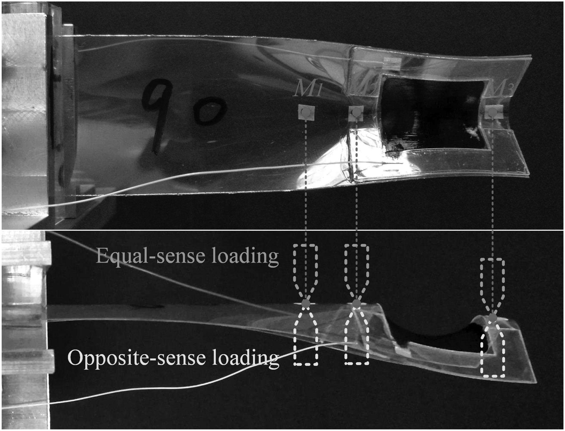
The front and top views of a clamped VSDEA prototype with length of 90 mm. The three loading points (M1, M2, M3) are indicated with dots, the probe marks illustrate the equal-sense and opposite-sense loading tests by the load cell during the experiments.

Experimental specimen of the VSDEAs with different lengths c. The lengths of specimen A, B, C are 100, 90, and 80 mm, respectively. M1, M2, and M3 indicate the loading points. l1, l2, and l3 are the distances of different loading points away from the clamped point O.
Results and Discussion
Effects of design parameters
Figure 7 shows the bending behavior of a 90-mm-long curved strip clamped by an arc fixture with radius Rf = 40 mm. The load was exerted on loading point M1 during the loading and unloading experiments. Compared with the 90-mm-long VSDEA, the tested curved strip had no prestretched DE film attached on the tip. The load/displacement relationship of this strip not only can reveal the effect of bioinspired clamping mechanism on the strip but also can describe the stiffness behavior of a VSDEA when the applied voltage is high enough to make the tip DEMES to fully unfold. For opposite-sense loading, the load goes up rapidly with the deformation displacement. As the displacement increases, a region between the fixture and the loading point of the strip flattens until the load reaches a maximum Fc called critical load. Then, the load drops dramatically, which attributed to the snap-through buckling of the curved strip leading to the formation of a fold. The buckling occurs at a deflection of 2.24 mm and the critical load is 119.8 mN as labeled in the figure. Once buckling occurs, the load remains about the same. Regarding the unloading of the loaded strip, the blue curve is first overlapped with the loading path, then extends and jumps back on the loading curve near the origin. The oscillations in the loading and unloading curves were truly recorded by the load cell and characterize the snap-through buckling of the curved strip. In equal-sense bending, the load first increases gradually with the displacement, and the stiffness is the same as that in opposite sense valued 10.3 N/m near the origin. Then, the bending behavior is defined by a constant steady-state load with small level. The unloading path almost coincides with the loading process. We can find that the bending behavior of this curved strip is very similar to tape springs, especially in opposite-sense bending.44,48 The stiffness and the load capacity of the curved strip in opposite-sense bending are much bigger than a flat strip and in equal-sense bending, due to the curvature-induced rigidity by the bioinspired clamping mechanism. In this article, we only focus on the opposite-sense loading behavior of the VSDEAs, which exhibits an enhanced performance.

Load/displacement relationship for a 90-mm-long strip without DE film, which is clamped by an arc fixture with radius Rf = 40 mm (as shown in inset). The loading point is M1. Gray: loading in opposite sense; dark gray: unloading in opposite sense; black: loading in equal sense; light gray: unloading in equal sense. The positions of the snap-through buckling are marked by circles. DE, dielectric elastomer.
The radius of the arc fixture has an important effect on the bending behavior of the VSDEAs. Once the fixture was decided, the curvature of the tip DEMES, which can be tuned by the applied voltage, determines the performance of the VSDEAs. Even a simple and easy-to-use theory and model of the DEMES developed by Liu et al. could simplify the tedious trial-and-error designing process 37 ; the variable curvature of the tip DEMES is still difficult to derive precisely in theory for its saddle-like DE film with complicated stress distribution.31,33,49 Here, the curvature radiuses R of the tip DEMESs in VSDEAs with different lengths when subjected to different applied voltages are measured from experiments as shown in Figure 8. We can see that the tip curvature radius increases as the applied voltage increases, which agrees with the conventional DEMES. Furthermore, the VSDEA with a longer strip has a bigger tip curvature radius when the prestrain of the DE films is the same. The initial curvature radiuses of the three VSDEAs with length c = 80, 90, and 100 mm are 23.0, 25.6, and 26.1 mm, respectively. The practical bending deformation of a 90-mm-long VSDEA is shown in Figure 8, and the initial configuration of the VSDEA can be referred in Figure 5. In the opposite-sense loading (Fig. 9a), we can see in a region of the VSDEA near the fixture occurs local buckling, leading to the concentration of the bending deformation in the buckling area with zero transverse curvature. Connected to the buckling area are two transition parts with variable transverse curvature, and the tip DEMES remained almost undeformed within a small deflection. In the equal-sense loading (Fig. 9b), a localized fold also occurs near the fixture and divides the strip into two transition parts and a fold part. The observed practical bending deformation of the VSDEAs during the experiments is consistent with the previous analysis in the Bioinspired Design and Variable Stiffness Mechanism section.

The relationship between the tip curvature radius and applied voltage for the VSDEAs with different lengths.

The top views of the prototype during opposite-sense and equal-sense loading experiments.
Figure 10a–e shows the bending behavior of the VSDEAs under different radiuses of arc fixture, actuator lengths, and loading points. The load/displacement curves are similar to that of the curved strip shown in Figure 7. We can learn the bending stiffness k and the load capacity Fc (represented by the critical load) of the VSDEAs from the opposite-sense loading curves. The values of critical load and the corresponding deflections are labeled in the figures. Figure 10a–c describes the effects of three arc fixtures with radiuses Rf = 20, 40, and 60 mm on the bending behavior of a 90-mm-long VSDEA at loading points M1, M2, and M3, respectively. They all display that the stiffness and the load capacity of the VSDEAs enhance as the curvature of arc fixture increases. It is easy to understand that the arc fixture with a larger curvature induces a bigger transverse curvature for the VSDEA, which needs more power to be folded. In addition, the VSDEA clamped by the arc fixture with radius Rf = 20 mm has much bigger k and Fc at loading points M1 and M2, than at loading point M3. It is mainly because M3 is located at the outside of the tip DEMES; when loading at point M3, the tip DEMES may unfold before the strip occurs buckling, which needs smaller force.

Effect of design parameters on the bending stiffness behavior of VSDEAs:
Figure 10d illustrates the difference of the bending behavior for a 90-mm-long VSDEA clamped by the arc fixture Rf = 40 mm at three different loading points. We can see that the closer the loading point is near the fixture, the bigger stiffness and load capacity it has. It can be easily explained that when the strip is subjected to the same bending moment, a longer arm of force leads to a smaller load. The bending stiffness of the initial flat strip at loading point M1 can be estimated by
From Figure 10e we can see the bending behaviors of three VSDEAs with different lengths (c = 80, 90, and 100 mm) at the same loading point M1, they are all clamped by the same arc fixture with radius Rf = 40 mm. The stiffness and load capacity of the 80-mm-long VSDEA are bigger than the other two VSDEAs for it has a bigger tip curvature. While the tip curvatures of the VSDEAs with lengths 90 and 100 mm are close, the bending behaviors of them are similar. In addition, we can observe that there are two snaps in the red opposite-sense loading curves in Figure 10a–c and e, it indicates that localized buckles occurred during the bending experiments. Some situations may induce these localized buckles: the VSDEA is not clamped symmetrically, which leads the external load unparallel to the symmetry plane of the VSDEA; the defects in the flexible strip.
Effects of applied voltage
For a given bioinspired VSDEA, the geometric parameters are determined, and then, its mechanical behavior is affected by the applied voltage. Figure 11a–k shows the stiffness behavior of the VSDEAs under different applied voltages. Figure 11a–i shows the load/displacement curves of a 90-mm-long VSDEA. Figure 11a–c, d–f, and g–i shows the load/displacement curves of the VSDEAs clamped by arc fixtures with three different radiuses Rf when loading at points M1, M2, and M3, respectively. The load/displacement curves of the VSDEAs with length 80 and 100 mm are described in Figure 11j and k, respectively. We can obviously see that the stiffness of the VSDEAs decreases as the applied voltage increases. The load capacity of the 90-mm-long VSDEA also reduces with the increase of applied voltage except when it is clamped by the arc fixture with Rf = 20 mm.

Effect of applied voltage on the bending stiffness behavior of VSDEAs:
As Figure 11a and d shows, the load capacities of the VSDEA at loading point M1 and M2 when clamped by the arc fixture with Rf = 20 mm remain about the same under different applied voltages. It is mainly because the curvature of this arc fixture is big, and it can induce a relatively long persistence length of curvature, which can be estimated by
In addition, we observe that the snap positions of the loading curves in Figure 11a, b, d, and e move backward with the increase of the applied voltage, and contrarily in Figure 11c and f–I, the snap positions move forward. It can be explained that in the former case, the buckling behaviors of the VSDEAs are dominated by the arc fixtures with a relatively big curvature, and the tip DEMESs have less effect on the moments for folding the curved strips; so, the snap positions move backward to ensure the work done by the load for inducing the buckling. Instead, in the latter case, the buckling behaviors of the VSDEAs are dominated by the tip DEMESs whose curvature can be tuned by the applied voltage, and so, the work done by the load for folding the strips decreases as the applied voltage increases, thus making the snap positions move forward. Moreover, it is worth mentioning that a part of the load/displacement curve of the VSDEA before snap-through buckling corresponding to each applied voltage is approximately linear, which is beneficial to the practical applications of stiffness control.
To reveal the relationships between the bending stiffness, the load capacity of the VSDEAs, and the applied voltage, we measure the slopes of the load/displacement curves near the origin, which can approximately evaluate the initial bending stiffness of the different VSDEAs when subjected to different applied voltages and the critical load of every loading curve. The curves of bending stiffness and critical load of the VSDEAs varying with the applied voltage are displayed in Figures 12 and 13, respectively. All curves show that the bending stiffness of the VSDEAs decreases as the applied voltage increases. Specifically, Figure 12a–c shows the stiffness/voltage curves of the 90-mm-long VSDEA clamped by arc fixtures with three different radiuses Rf when loading at points M1, M2, and M3, respectively. Corresponding to each voltage, the arc fixture with a bigger curvature induces bigger transverse curvature of the strip, thus leading a higher bending stiffness for the VSDEA.

Curves of bending stiffness varying with applied voltage for the VSDEAs:

Curves of critical load varying with applied voltage for the VSDEAs:
Figure 12d compares the stiffness of the 90-mm-long VSDEA corresponding to different applied voltages when loading at different points. We can see that the closer the loading point approaches the fixture, the larger the stiffness the VSDEA has, which attributes to the same reason as explained in Figure 10d. The relationships between the bending stiffness and applied voltage of three VSDEAs with different lengths are illustrated in Figure 12e. Under each applied voltage, the VSDEA with shorter length has a bigger transverse curvature as shown in Figure 8, so it has a bigger bending stiffness. We also find that the relationship between the bending stiffness of the VSDEAs and the applied voltage is approximately linear excluding the errors induced by the measurements.
Figure 13a–e describes the critical load/voltage curves of the VSDEAs corresponding to the cases in Figure 12a–e, respectively. The critical load of the 90-mm-long VSDEA reduces with the increase of applied voltage (Fig. 13a–d), and the critical load of the VSDEAs with lengths 80 and 100 mm has no clear relationship with the applied voltage as shown in Figure 13e. Figure 13a–d shares the same characteristics of the VSDEAs with Figure 12a–d. The critical load/voltage curves of the VSDEA clamped by the arc fixture with Rf = 20 mm are not drawn in Figure 13a and b, because the values of these curves are much higher than the green and blue curves in the same figure and remain unchanged with the applied voltage.
Tables 2–5 list the parameters of the bending stiffness and critical load of the VSDEAs corresponding to 0 and 5.6 kV when loading at different points and clamped by different arc fixtures. λk is the relative stiffness change and λF is the relative critical load change, they can be calculated through the ratio of the variation between 0 and 5.6 kV to the value at 0 kV. We can see that when the applied voltage ranges from 0 V to 5.6 kV, the relative stiffness change can reach about 71.8% when c = 90 mm, Rf = 60 mm, and loading at M2 (Table 3), and the relative critical load can reach about 75.6% when c = 90 mm, Rf = 60 mm, and loading at M3 (Table 4). The maximum stiffness and critical load are, respectively, 157.8 N/m and 889.9 mN for the case of the 90-mm-long VSDEA at loading point M1 with Rf = 20 mm, which are two orders greater in magnitude than that of our previous work, 31 but the λk and λF are small in this case (Table 2). The 90-mm-long VSDEA weighs 0.64 g, so in this case the VSDEA can bear a payload 139 times its weight. When the VSDEA is clamped by the arc fixture with Rf = 60 mm or loaded at point M3, it exhibits a good comprehensive performance in λk and λF, but for these cases the absolute values of the stiffness and critical load are relatively small. Even so, the stiffness and load capacity of the bioinspired VSDEA are enhanced a lot, compared with our previous work, which are under 5 N/m and 10 mN, and the relative stiffness change basically maintains on the same order of magnitude. Moreover, the load capacity can also be tuned by the applied voltage.
Parameters of the Bending Stiffness and Critical Load of the 90-mm-Long Variable Stiffness Dielectric Elastomer Actuator When Loading at Point M1 and Clamped by Arc Fixtures with Different rf Corresponding to Different Applied Voltages
k is the bending stiffness; Fc is the critical load; λ k is the relative stiffness change; λ f is the relative critical load change.
Parameters of the Bending Stiffness and Critical Load of the 90-mm-Long Variable Stiffness Dielectric Elastomer Actuator When Loading at Point M2 and Clamped by Arc Fixtures with Different r f Corresponding to Different Applied Voltages
Parameters of the Bending Stiffness and Critical Load of the 90-mm-Long Variable Stiffness Dielectric Elastomer Actuator When Loading at Point M 3 and Clamped by Arc Fixtures with Different r f Corresponding to Different Applied Voltages
Parameters of the Bending Stiffness and Critical Load of the Variable Stiffness Dielectric Elastomer Actuators with Lengths 80 and 100 mm When Loading at Point M 1 and Clamped by Arc Fixtures with r f = 40 mm Corresponding to Different Applied Voltages
Although the relative stiffness changes of the VSDEAs with lengths 80 and 100 mm when loading at point M1 and clamped by the arc fixture with Rf = 40 mm can reach about 69.2% and 40.9%, respectively (Table 5), their critical loads are almost unchanged with the applied voltage. From the above results we deduce that when the 80-mm-long VSDEA is clamped by the arc fixture with Rf = 60 mm, the critical load can be tuned by the applied voltage. The experiment in Figure 14 verifies our deducing; as can be seen, a mass with weight W = 25.3 g is hung steadily on the 80-mm-long VSDEA at the point that is 40 mm far from the fixture (Fig. 14a). The 80-mm-long VSDEA weighs 0.6 g, so the VSDEA bears a payload 42 times its weight. When a 4 kV high voltage is applied on the tip DEMES, the VSDEA collapses immediately, which indicates that the load capacity of the VSDEA reduces after the voltage is applied. In conclusion, this bioinspired design achieves a big improvement on the stiffness and load capacity for the DEAs based on DEMESs, and also provides powerful functions of variable stiffness and load capacity.

Experiment of load capacity tuning for an 80-mm-long VSDEA.
Conclusions
In summary, a bioinspired clamping mechanism is proposed for designing bioinspired VSDEAs with large and tunable load capacity. The bioinspired VSDEA looks like a piece of monocot leaf, it consists of a curved strip with a tip DEMES, and is clamped by an arc fixture that imitates the connection mode between the leaf and the cylindrical stem of the monocot. Several bioinspired VSDEAs with different lengths are fabricated. Then, the bending behaviors of the VSDEAs are experimentally investigated. The effects of applied voltage and design parameters (actuator length, loading position, and radius of the arc fixture) on the stiffness behavior are systematically studied. The experimental results demonstrate that when applying voltage on the tip DEMES, the bending stiffness of the VSDEA decreases as the voltage increases, which is due to the voltage-induced variation of the transverse curvature of the curved strip. The VSDEA clamped by the arc fixture with bigger curvature and the loading point on the VSDEA that is closer to the fixture have greater stiffness corresponding to each applied voltage. The shorter VSDEA also has a bigger stiffness corresponding to each voltage. The load capacity of the VSDEAs is enhanced a lot due to the curvature-induced rigidity and can be also tuned by the applied voltage. Finally, we conduct an experiment of load capacity tuning for the VSDEA, and the result shows that the VSDEA can bear a payload 42 times its weight and it turns soft and collapses immediately when a high voltage is applied on the tip DEMES. Moreover, the proposed bioinspired variable stiffness mechanism has a good scalability and can be also implemented by other smart materials. Soft robots and rehabilitation devices can be designed based on this bioinspired mechanism, which can significantly enhance the load capacity of soft actuators. In conclusion, this bioinspired design achieves a big improvement on the stiffness and load capacity for the DEAs based on DEMESs, and also provides powerful functions of variable stiffness and load capacity. Also, it shows great potential in different applications, such as soft robots, vibration control, and morphing structures.
Footnotes
Acknowledgments
The authors gratefully acknowledge the support by the National Science Foundation for Distinguished Young Scholars (Grant No. 11625208), the National Natural Science Foundation of China (Grant Nos. 91748118 and 11572190), the National Program for Support of Top-Notch Young Professionals.
Author Disclosure Statement
No competing financial interests exist.