




Abstract
Abstract
In this article, we demonstrate elementary slender soft robots mimicking the skeleton joint system of animals with excellent locomotion performance and scalability. Inspired from bending characteristics of mammal joints, the soft joint, consisting of two Pneu-nets (PNs), one with three chambers and the other with two chambers, was developed. By using simple constraints and connections, the soft joint can be separately controlled by 180° bending and unbending, and exhibits large force output with limited volume and deformation. Then, a skeleton joint-like slender robot was proposed by including a different number of the soft joint and stiff skeleton for different functionalities. This robot exhibits excellent locomotion performance due to the skeleton joint design to achieve large deformation level and proper selection of gait to fully utilize the skeleton joint-like motion, that is, moving 0.5 body length per loading cycle and navigating both continuous terrains, such as a slope, and unprecedented terrains with “discrete” obstacles, such as a wall and stairs. Besides, the slender soft robot is scalable in joint and skeleton, and additional tuning joints can be introduced to achieve turning and spinning locomotion. The slender robot presented herein has not only the advantages of simple fabrication, light weight, good adaptability and scalability, and human-friendly interface but also provides insights for future development of mobile soft robots.
Introduction
Recently, soft robots made of soft actuators have attracted much research attention due to their compatibility with human bodies, adaptability to complex environments, multifunctionality, and easy fabrication, which nearly cannot be implemented by traditional hard robots.1–7 Potential applications of soft robots include medical rehabilitation, 8 manipulating fragile or unknown objects,9,10 search-and-rescue operations, 2 and so on. Inspired by natural biological systems, many types of terrestrial soft robots have been proposed, examples including snake-like slithering locomotion,1,3,11 multigait quadruped,2,7 caterpillar-inspired soft robots,12,13 and worm-inspired soft robots. 14 However, these bioinspired robots usually suffer from low locomotion efficiency3,4,11 and limited adaptability to complex terrains, compared with their biological counterparts, for example, Lumbricus terrestris, 14 snake, 1 and Oligochaeta. 15
One of the reasons for these drawbacks is that the bioinspired soft robots lack skeleton and they deform the whole body for locomotion. While for animals, usually consisting of skeleton joints, the deformation is concentrated at the joints, easily achieving large deformation, high load capacity, and locomotion efficiency. Therefore, Nemiroski et al. proposed another class of soft robots, that is, arthrobots, using plastic tube as exoskeleton and pneumatic cell as joint, with good adaptability. 5 However, their robots still suffer low locomotion efficiency and large outline unusable in narrow space.
As the evolution of biological system, the structure and functionality of animals become more and more complicated. However, the skeleton joint system seems the fundamental component of higher animals. In this work, we intend to mimic the skeleton joint system of animals to construct high-performance soft robots. As the key part in the skeleton joint system, many soft joints have been investigated during the past decade, such as using soft actuator to achieve bending deformation and the passive resilient component, for example, elastomeric tendon 5 or fiber reinforcement 8 to achieve unbending deformation. However, the unbending deformation caused by the passive resilience is essentially different from the active contraction of muscle of biological system.
Therefore, the previous soft joints usually need large actuation pressure and have limited bending angle, for example, the “arthrobot” joint worked at a pressure of 200 kPa with a bending angle of about 70°. 5 Besides, bidirectional fluidic elastomer actuators (FEAs) are a potential way to achieve bidirectional bending, but this method has not been used in soft joints because the bidirectional FEAs need lots of chambers along with great pressure to generate limited bending angle, for example, 25 chambers working at a pressure of 290 kPa were needed to generate bidirectional 180° bending for the fish actuator. 16
Schulz et al. used 24 pairs of soft joints, which consisted of balloons and metal limbs, and antagonistically worked to construct an eight-leg pneumatic spider. However, these soft joints could only bidirectionally bend by a maximum angle of 35° due to the rigid structures of metal limbs in the soft joints, which were also unfriendly for human body interface. 17 For the joint of natural spider, it could bend up to 160°, 18 while for the joint of limbed mammal, it could bend and unbend in a range of 0–180°, 19 and hold the bending state at any bending angle. Compared with the joint of biological system, there are a lot of shortcomings for the previous soft joints, such as small bending angles, high actuation pressure, and complex structures. Much attention should be paid to developing high-performance soft joints to fully explore the ability of joints of the biological system.
To overcome the drawbacks of previous soft robots and soft joints, in this work, we propose an elementary slender soft robot consisting of skeleton joint system. The soft joints can bend up to 180°, making the soft robot move efficiently in complex terrains, and the slender outline is favorable in the search-and-rescue missions.11–15 Besides, the slender soft robot proposed in this work is elementary, which consisted of different numbers of skeleton joint to achieve different functionalities, such as locomotion, turning, spinning, and climbing.
The elbow joint of human arm 20 is the key inspiration of our soft joint, which has three elements: (i) a pliable hinge allowing the relative rotation of skeleton, (ii) the contraction of triceps brachii muscle generating 180° bending, and (iii) the contraction of biceps brachii muscle recovering to the unbending state, see Figure 1A–C. In this work, we only mimic the functionality of elbow joint, which uses two antagonistically worked muscles to separately control the bidirectional bending and unbending, and we do not use any tendon 21 to mimic muscles, which may make the structure complicated or rigid (shape memory alloy). 22

Schematic illustrations of the elbow joint of human arm and the mammal-inspired soft joint.
Experimental Design
In the previous literature, there is no soft joint exhibiting 180° bending and unbending, and large force output with limited volume and deformation. Based on the mature design of Pneu-nets (PNs), 23 we used a pair of PNs, including a three-chambered PN for bending deformation and a two-chambered PN for unbending deformation to construct the soft joint. The schematic illustrations of the mammal-inspired joint are shown in Figure 1D–F and its working state is presented in Supplementary Movie S1. The brief fabrication process of the soft joint is as follows: (i) fabricating the two PNs with silicone rubber (Ecoflex 00-30; Smooth-On, Inc.) and inserting the polyurethane tubes to the PNs as the air supply channel; (ii) adhering printer paper and plastic sheet to the three-chambered PN to increase its stiffness and constrain large lateral expansion; (iii) tying the two PNs with plastic wire; and (iv) connecting eight hollow beams to the three-chambered PN to construct the skeleton joint system, as shown in Supplementary Figure S1. Here the hollow beam was rolled by printer paper for its lightweight and easy access.
The constraints were applied to the three-chambered PN to constrain the lateral expansion of specific outside walls, as the bending of soft joint was mainly determined by the longitudinal expansion of the three-chambered PN and the lateral expansion was useless for bending but could cause inconvenience for the connection between the skeleton and joint, as well as severe instability during locomotion, discussed in the Elementary Slender Soft Robot section. These constraints were also beneficial to increase the stiffness and force output of the soft joint, as shown in the Force Output of the Mammal-Inspired Joint section.
There were two key points to alleviate the obstruction of two PNs during bending and unbending; first, the two PNs were tied together by wire instead of glue or integrated molding, which allowed relative sliding between the two PNs, and second, the two PNs had different length, that is, the length of the two-chambered PN was only half of the three-chambered PN. As a result, the actuation pressure of the soft joint was significantly decreased, while the bending angle was increased, overcoming the shortcomings of bidirectional FEAs. Besides, the soft joint presented in this work could separately bend and unbend at any angle from 0° to 180°, which could fulfill the requirement of locomotion in complex terrain, and the reduced actuation pressure was also beneficial to increase the life span of the soft joint.
Figure 1G–I shows the separately controlled bending and unbending of the soft joint. When the three-chambered PN was pressurized to 38 kPa, it bended to 180°, and it restored to the original position when the two-chambered PN was pressurized to 20 kPa. A detailed process of the experiment is found in Supplementary Movie S1. Note that the skeleton (i.e., the hollow beams) can be adhered to different positions of the joint at different angles, so that a series of skeleton joint systems can be assembled to elementary soft robots with a predesigned structure to achieve different functionalities, as shown in the Turning Locomotion section. Instead of using hydraulic actuator, we chose the pneumatic actuator due to its light weight, convenience, and excellent mobility in small structures. Here the actuation pressure for 180° bending was just 38 kPa, much smaller than that of the joint of “arthrobot,” which was 200 kPa for only 70° bending. 5
Results
Force output of the mammal-inspired joint
The force output of the soft joint at different actuation pressures was measured, that is, in the relaxed state (left figure in Fig. 2A), one side of the joint was fixed and a block with mass M was tied to the other side of the joint, and then, we gradually increased the actuation pressure until the soft joint bending 90° (right figure in Fig. 2A). Here the gravity of the block was F = Mg (g = 9.8 m/s 2 ), which equaled to the output force of the soft joint. Different mass of the block was tied to the soft joint and the corresponding pressure for 90° bending was recorded, so that the relationship between the force output and actuation pressure was obtained, as shown in Figure 2B. The safe pressure of the soft joint was 43 kPa, corresponding to the force output of 6 N, and higher pressures might cause failure (overinflation) of the soft joint. As a comparison, the output force of the sleeved joint of “arthrobot” was only 1.2 N for the actuation pressure of 200 kPa. 5 Besides, the force output for the constrained three-chambered PN was also measured to study the effect of the two-chambered PN on the bending behaviors of the soft joint. It is found that the output force-applied pressure curves are almost overlapped, which further verifies that the deformation of the two PNs is independent and the bending and unbending of our soft joint can be separately controlled.

Force output of the soft joint.
The force output of the unconstrained three-chambered PN was further measured, which showed the safe pressure was 30 kPa corresponding to the maximum force output of 1.5 N, much smaller than that of the constrained three-chambered PN, as shown in Figure 2B. Therefore, the constraints can increase the safe pressure of the three-chambered PN and significantly enhance the output force. Indeed, a similar force output (i.e., 1.4 N at actuation pressure of 35 kPa) was observed in the previous unconstrained PN. 24
Elementary slender soft robot
The elementary slender soft robot was constructed by connecting four soft joints with the hollow tube skeleton at proper angle and position, as shown in Figure 3A. Two polyvinyl chloride (PVC) plates were adhered to the two ends of the slender soft robot to serve as feet of the robot. Two silicone rubber sheets (Ecoflex 00-30; Smooth-On, Inc.) were pasted at the bottom of the PVC plates to increase the friction to avoid sliding of the soft robot during locomotion. The length of the slender robot was 30 cm and the weight was 92 g. Here the width of the PVC plates was 10 cm larger than that of the soft robot body (3 cm) to increase its transverse stability.
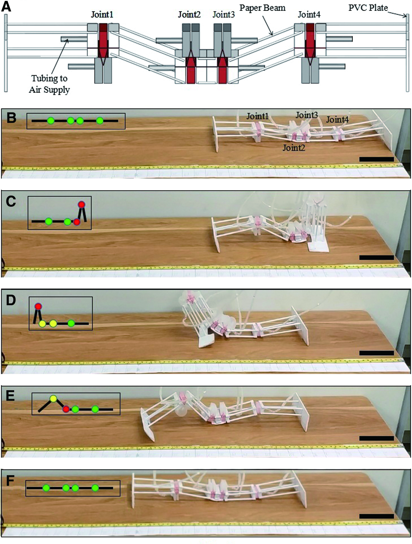
Structure and locomotion of the elementary slender soft robot.
The bending direction of the two edge soft joints is downward, while the bending direction of the two middle joints is upward. The length of the skeleton of adjacent joints was properly adjusted to increase the locomotion efficiency of the slender soft robot. It should be noted that the skeleton used in this work is only relatively stiffer than the soft. The moduli of materials, including silicone rubber (10 5 Pa), paper (10 8 Pa), plastic sheet (10 8 Pa), are in the range of soft materials, that is, the moduli of soft materials are usually in the range of 10 4 –10 9 Pa. 6 Therefore, the skeleton joint robot proposed in this work is also a fully soft robot that has the advantages of soft robots, such as safety to the human body and good adaptability.
The locomotion of the soft robot was actuated by sequentially inflating the joints. Each joint had two working states, that is, the bending state by pressurizing the three-chambered PN and unbending state by pressurizing the two-chambered PN. The bending, unbending, and rest states of the soft joints are represented by red, yellow, and green cycles in the left inset of Figure 3B–F, respectively. In general, the four joints involved eight deformation states, which could be independently controlled by connecting the eight air channels and a series of solenoid valves (VT307; SMC, Inc.) and proportional pressure valves (ITV0050; SMC, Inc.) to a PLC control system (CJ2M-CPU11; Omron, Inc.).
From the rest state (Fig. 3B), the locomotion of the slender soft robot had three steps: (i) bending joint 3 (90°) and joint 4 (180°) pulled the back part of the soft robot to the center (Fig. 3C) and the front part kept stationary due to the friction force at the front PVC plate; (ii) unbending joint 3 and joint 4, and sequential bending joint 2 and joint 1 to pull the center part of the soft robot forward (Fig. 3D). At this step, the two PVC plates kept stationary and the motion focused at the center part of the soft robot; and (iii) unbending joint 1 to push the front part of the soft robot forward (Fig. 3E). Indeed, during locomotion, there is no sliding between the soft robot and ground, and the motion efficiency, defined as the ratio of the locomotion distance in one loading period to the maximum dimension of the soft robot, can be in a wide range from 0 to 0.5.
For the slender soft robot and actuation method shown in Figure 3, the motion efficiency was 0.5. While for the adaptability to complex terrain, such as moving over obstacle, climbing inclined plane and stair, the motion efficiency might be sacrificed, as discussed in the Adaptability for Complex Terrain section. Note that joint 4 was simplified to a three-chambered PN since the unbending of joint 4 was not required for the forward walking locomotion. However, the current structure of the slender soft robot is able to move either backward or forward due to its symmetric structure, as shown in Supplementary Data.
To theoretically analyze the locomotion of the slender soft robot, a beam joint model is proposed, as shown in Figure 4A. Several assumptions are made to simplify the theoretical analysis. (a) As the locomotion of the soft robot is one dimensional, the transverse motion of the beam joint model is ignored. (b) As the length of the soft robot is much larger than the height, the effect of the soft robot height on the locomotion on flat plane is neglected, but the for the climbing of stair or inclined plane the effect of the height is not negligible, considered in the Adaptability for Complex Terrain section. (c) The length of the joint and PVC plate are small quantities compared with the length of the beams, so their effects on locomotion are ignored. While the mass of the joint (m3) and PVC plate (m4) play an important role, which is considered in our theoretical model. For the three steps illustrated in Figure 4B, the displacement of the mass center of the soft robot can be expressed as follows:

Theoretical analysis of the locomotion of the slender soft robot.
Hence, the total displacement of the soft robot in one cycle is d = dI + dII + dIII. As the four joints are individually controlled, we can design a symmetrical gait with θ1 = θ1′ = θ4 and θ2 = θ2′ = θ3, and the displacement d can be further expressed as follows:
Then, the motion efficiency can be derived as E = d(θ3,θ4)/(2(L1 + L2)), which is E = 0.5 for (θ3,θ4) = (90°, 180°), as shown in Figure 3 and Supplementary Movie S2.
Assuming L1 = L2 and considering that θ3 andθ4 have a geometry relationship L1/sin(θ4 − θ3) = L2/sin(θ3), the motion efficiency can be simplified as follows:
For 180° ≥ θ3 ≥ 0°, E increases monotonously with the increase of θ3, which means that theoretically E can go beyond 0.5 when θ3 ≥ 90° and θ4 ≥ 180°. However, for the designed joint, the maximum bending angle is 180° so the slender soft robot cannot implement this experiment yet. By using finite-element method (FEM) simulation, a slender robot model that can move with E of 0.6 is shown in Supplementary Data, which verifies the theory. For the proposed gait of locomotion, there is a maximum E beyond which in step (ii) the center part cannot be pulled forward so that locomotion fails. The critical condition corresponding to maximum E is shown in Supplementary Equation (S1) and a maximum motion efficiency 0.74 is obtained when (θ3,θ4) ≈ (138.5°, 263°).
The designed joint includes two PNs, and for each PN, the inflating and deflating rates are defined as the angle of bending and unbending per unit time. So, the inflating and deflating rates of the three-chambered PN and two-chambered PN are denoted as r3_inf, r3_def, r2_inf, r2_def, respectively. The locomotion speeds of three steps illustrated in Figure 4B are vI = dI(r3_inf + r3_def)/θ4, vII = dII(r3_inf + r3_def)/θ4 and vIII = dIII(r2_inf + r2_def)/θ4 and the locomotion speed per one loading cycle is as follows:
Generally, larger inflating and deflating rates can induce higher locomotion speed. For the proposed joint and pneumatic control system r3_inf ≈ 90°/s, r3_def ≈ 180°/0.2 s, r2_inf ≈ 90°/s, and r2_def ≈ 90°/s so the theoretical maximum v of the slender soft robot is 2.34 cm/s or 0.078 body length per second. In the experiment, we added small pauses between different steps to ensure the stability of locomotion so that in Supplementary Movie S2, v was 0.056 body length per second or 1.67cm/s.
Adaptability for complex terrain
The adaptability for complex terrain is very important for soft robots. However, the previous soft robots were usually hard to cross the “discrete” obstacles such as stair or wall, as the locomotion mode for most of the previous soft robots was sliding on the ground and the lack of skeletons could not lift their bodies to cross the discrete obstacles. Figure 5 and Supplementary Movies S3,S4,S5,S6 show the slender soft robot crossed several types of discrete terrains, including a wall, one stair, and three stairs. The climbing of an inclined plane was also studied. In these experiments, the structure and actuation method of the soft robot were the same as that of the soft robot on the flat plane. The only difference was that the actuation pressure of the joints was slightly different to adapt different terrains. For example, for climbing the stairs or inclined plane, the joint 1 needed higher pressure to provide larger thrust for locomotion.

Terrain adaptability of the slender soft robot.
In the preliminary experiment, the slender soft robot had successfully climbed a 20° inclined plane. It is very interesting to theoretically predict the maximum climbing angle and the motion efficiency of the soft robot on inclined plane. The critical condition for the soft robot climbing on the inclined plane at motion efficiency of 0.5 (i.e., θ3 = 90° and θ4 = 180°) is shown in Figure 6A. Under critical condition, the gravity of joint 4 (m3g) and right end beam (m2g) generate clockwise torque around point O. When the inclined angle exceeds a critical value, clockwise torque would result in clockwise rotating of the right end beam and sliding down of the soft robot along the inclined plane. The friction force f at left end of the soft robot can prevent the rotation and its equivalent force at joint 4 is F. According to the force diagram in Figure 6A, the maximum climbing angle αmax of the soft robot with respect to motion efficiency 0.5 can be derived as follows:

Theoretical analysis for climbing an inclined plane of the soft robot.
where μ is the friction coefficient between the silicone rubber and inclined plane (PVC plate). Substituting the parameters in experiment (Fig. 5D), that is, μ = 1, L1 = 0.075 m, L2 = 0.1 m, h = 0.02 m, m1 = 3 g, m2 = 4 g, m3 = 16 g, and m4 = 7 g into Equation (7), we obtained that the maximum climbing angle is αmax ≈ 21°.
Actually, the climbing angle of the soft robot can be larger than 21°, if its motion efficiency is sacrificed (smaller than 0.5). Figure 6B shows the maximum feasible motion efficiency taken by the soft robot for the climbing angle 21° < α < arctan(μ). At the end of step I, θ3 and θ4 can be adjusted so that the right end beam is parallel to the gravity direction and there is no driving force for the rotation around point O. Based on the geometrical relationship among α, θ3, and θ4, the upper limits for θ3 and θ4 are θ3 ≤ 90°-α and θ4 ≤ 180°-2α, respectively. Hence, the maximum feasible motion efficiency was estimated as Emax = d(90° − α,180° − 2α)/(2(L1 + L2)), which is Emax ≈ 0.18 for α = 40°. The experimental studies of the slender soft robot on different inclined planes will be conducted in the future.
Turning locomotion
Indeed, the slender soft robot developed in this work is elementary, which can include different numbers of skeleton joints to easily achieve different functionalities. For example, using two two-chambered PNs, we designed a turning joint that can generate ±90° bending. Geometry parameters and fabrication process of the turning joint are shown in Supplementary Figure S2, similar to the mammal-inspired joint described in the Experimental Design section. Here the two-chambered PN was also constrained by paper to increase its stiffness and limit the large lateral expansion. The two two-chambered PNs were tied together by plastic wire. The difference is that the turning joint comprised two two-chambered PNs, which resulted in symmetric turning deformation. By integrating two turning joints into the slender soft robot, a slender robot with turning ability was constructed, as shown in Figure 7A.

Turning locomotion of the slender soft robot.
The turning locomotion comprised five steps from the rest state (Fig .7B): (i) bending joint 2 and unbending joint 1 to lift the front end of the soft robot and hold (Fig. 7C); (ii) bending turning joint 1 to make the front end turn left while the rest of the soft robot kept stationary (Fig. 7D), which induced strain energy in bending joint 2 and was constrained by friction; (iii) bending joints 3 and 4 to pull the back end of soft robot to the center, meanwhile the center and back end of the soft robot turning left due to the release of strain energy in bending joint 2 (Fig. 7E); (iv) unbending joints 2 and 3 to lift the center of the soft robot and bending joint 1 to pull the center of the robot forward (Fig. 7F); (v) unbending joints 1 and 3 to push the front end of the soft robot forward (Fig. 7G, H).
In this way, the soft robot turned left by 55° and moved forward one period distance of the translational locomotion. Actually, the front end of the soft robot turned left by 80° in step II and turned a little backward in step III due to the friction in the center of the soft robot. Because this robot had symmetrically distributed joints, it could also turn right and walk forward, or turn left or right and walk backward, which was an arbitrary planar motion. A more complex planar motion of this robot is also shown in Supplementary Movie S7.
In the proposed turning locomotion, translational locomotion was necessary, which might take more time and space. Therefore, we proposed a spinning locomotion that could turn with the center of the robot fixed. The spinning locomotion comprised five steps from the rest state (Fig. 8A): (i) bending of joints 2 and 3 and unbending of joints 1 and 4 to lift the front end and back end of the soft robot (Fig. 8B); (ii) bending of the turning joints 1 and 2 to make the front end turn left and back end turn right while the center of the robot kept stationary (Fig. 8C); (iii) bending of joints 1 and 4 to make the front end and back end support the robot (Fig. 8D) (note that this motion might decrease the normal force and friction at the center of the robot, but the center of the robot could still keep stationary by properly designing the turning gait); (iv) unbending of joints 2 and 3 and depressurization of two turning joints to turn the center of the robot in a line with the two ends (Fig. 8E); and (v) unbending of joints 1 and 4 to put down the two ends (Fig. 8F–G). This spinning locomotion could turn 42° in one loading cycle, which was smaller than the 52° generated by turning locomotion, in Figure 7, due to larger friction at the center of the robot in step iv for the spinning locomotion.

Comparison of locomotion performance
The motion efficiency3,7,11,12,16 (the ratio of the locomotion distance in one loading period to the maximum dimension of the soft robot) and deformation level3,11,12,16 (the ratio of the maximum size to minimum size of the soft robot in one loading cycle) of the proposed slender soft robot were compared with some previous soft robots and biological systems, as shown in Figure 9. Because of the skeleton joint design of our soft robot, it could easily achieve large deformation so as to have the highest motion efficiency compared with the previous soft robots. The locomotion speed of the slender robot in Supplementary Movie S2 is 0.056 body length per second or 1.67 cm/s compared with 0.36 cm/s of quadrapod. 7 By using faster pneumatic supply and control system, the locomotion speed of robot can be faster. The locomotion energy efficiency 4 (the ratio of effective locomotion energy to input mechanical energy) of the slender robot is 0.00045% compared with 0.000072% of untethered quadrapod.2,4 The detailed calculation process of locomotion energy efficiency is shown in Supplementary Data. Besides, we compared the turning efficiency (the ratio of the turning angle in one loading cycle to 90 degrees) of the proposed turning and spinning soft robots to several previous soft robots, as shown in Figure 10. The proposed turning robot has the highest turning efficiency and is five times larger than that of the quadrapod. 2

Comparison of the motion efficiency and deformation level between present work and several previous soft robots and biological systems (snake-like robot, 11 milk snake, 1 earthworm, 14 peristaltic locomotion, 15 caterpillar-inspired robot, 12 arthrobots, 5 a quadruped, 7 and an untethered quadruped 2 ).

Comparison of the turning efficiency between present work and some soft robots before.
Our robots have excellent motion and turning efficiency mainly due to the skeleton joint design of the soft robot structure and careful selection of the gaits. First, the skeleton joint design makes the deformation locate at the soft joint, and the stiff skeleton provides the load bearing, which is easy to achieve a large deformation level. Second, the proper selection of gait can fully utilize the skeleton joint-like deformation to achieve high motion efficiency and navigate complex terrains such as a wall and stairs. Besides, the skeleton joint design is also helpful to decrease the robot weight since the skeleton can be fabricated by light-weighted materials. Except for excellent locomotion performance and adaptability, our robots are scalable in joints and skeleton, for example, the turning joints can be integrated into the soft robot to achieve turning functionality.
The configuration of the skeleton can be further optimized to increase the motion efficiency of the soft robot. For example, the maximum motion efficiency of the soft robot presented in the Elementary Slender Soft Robot section was 0.5. Indeed, the skeleton configuration is easy to adjust. Through FEM simulation, it is shown that the motion efficiency could be up to 0.6 by using two U-shaped beams at two ends so that joint 1 and 4 can bend beyond 180°. The parameters of the FEM model are presented in detail in Supplementary Figure S3 and Supplementary Movie S9.
The proposed robot may have the transverse and longitudinal instability problem during locomotion. For the transverse instability, the slender outline of the soft robot makes it easy to roll over when any part of robot is lifted. Second, the proposed joint shows a slight rotational deformation when it bears loading from other parts of the robot; for example, in Supplementary Movie S5, the direction of robot turned a little leftward after the climbing of three stairs because joint 2 made a little anticlockwise rotation (take motion direction as axis) every time the front part of robot was lifted. To solve the two problems, two wide PVC plates are adhered at two ends of the robot and the joints are designed with relative large width. For longitudinal stability, the locomotion gait is carefully designed to avoid the turn over motion especially in the climbing of inclined plane.
Concluding Remarks
In this article, elementary slender soft robots with excellent locomotion performance and adaptability are developed. The skeleton joint design and proper selection of gait are two key factors for the slender soft robot. Inspired from the bending characteristics of mammal joints, the soft joint comprised two antagonistic PNs, which can achieve separately controlled 180° bending and unbending, and shows much higher force output and smaller applied pressure compared with the previous soft joints by applying simple constraints and connections. Then, an elementary slender robot is fabricated by combining four joints and skeletons with maximum motion efficiency of 0.5 and good adaptability for both continuous terrains such as a slope and unprecedented terrains with “discrete” obstacles such as a wall and stairs. Besides, the slender soft robot is scalable in joint and skeleton, and additional tuning joints can be introduced to achieve turning and spinning locomotion with maximum turning efficiency of 0.57.
The slender soft robots presented herein have the advantages of high motion and turning efficiency, unprecedented adaptability to complex terrains, slender outline for moving in narrow spaces, and easy fabrication. However, our soft robots also have some drawbacks, for example, the “hard” parts of stiff skeleton are not fully compatible with the soft counterparts and the possible solution is selecting proper soft materials that can satisfy the stiffness requirements of skeleton and soft robot. Another problem is the low actuation frequency caused by limitation of air flow in the PN channels, which is a common issue in pneumatic soft robots. Some solutions such as using larger compressors and air tubes may partially solve this problem. Replacing pneumatic soft joints with other soft actuators (dielectric elastomer and shape memory alloy) is another option, even though significant development is required for these actuators.
The proposed slender robots are scalable in joint and skeleton, not only bringing more design freedoms of soft robots but also providing many opportunities for future development of soft robots. For instance, integration of turning joints can achieve turning and spinning locomotion. In another example, the optimized skeleton can move 0.6 body length in one loading cycle. Besides, limbs can also be integrated to the slender soft robot to form arthrobots 5 such as spider or centipede. We believe that specially designed soft joints herein can significantly increase locomotion performance of arthrobots.
The fruitful design of locomotion gaits (i.e., the number of joints, length between adjacent joints, actuation sequence of joints) makes the soft robot mimic the locomotion of many types of animals, such as the proposed efficient locomotion and gait of control are very useful, sharing similar value of locomotion of natural soft animals, for example, snake-like slithering locomotion and caterpillar-like locomotion. Therefore, we think the skeleton joint soft robot proposed in this work can inspire a lot of following works, which may significantly improve the performance of soft robots. The proposed locomotion and gait can be implemented by different materials and actuations under different requirements. In future works, we will upgrade the “tethered” robots (including external air supply and valves) to untethered robots (all components on board),2,25–28 and try to study the general strategy for gait design. The proposed skeleton joint design and high-performance soft joint hold great potential application in the field of land mobile soft robots.
Footnotes
Acknowledgments
Y.L. acknowledges the support from the National Natural Science Foundation of China (No. 11572239). X.C. acknowledges support from the National Natural Science Foundation of China (11572238 and 11872302), Key R & D Program of Shaanxi (2018ZDXM-GY-131), and Yonghong Zhang Family Center for Advanced Materials for Energy and Environment. P.Y. acknowledges the China Scholarship Council for financial support.
Author Disclosure Statement
No competing financial interests exist.

References
Supplementary Material
Please find the following supplemental material available below.
For Open Access articles published under a Creative Commons License, all supplemental material carries the same license as the article it is associated with.
For non-Open Access articles published, all supplemental material carries a non-exclusive license, and permission requests for re-use of supplemental material or any part of supplemental material shall be sent directly to the copyright owner as specified in the copyright notice associated with the article.
