In this work, we design a type of soft robots for flipping locomotion, called the FifoBots. Different from most of the current soft robots that perform crawling, rolling, or jumping locomotion, the proposed FifoBots can flip forward and backward like a piece of self-foldable paper. The FifoBots have simple actuation and avoid complicated balance control. This article presents the principle and analysis of the flipping locomotion as well as the prototypes and experiments of the FifoBots. Two schemes of the flipping locomotion are proposed, and each scheme has the linear and quadrilateral morphologies, enabling the straight and biaxial movements, respectively. The movement performance in each stage of the flipping locomotion is analyzed oriented to the parameter design. The prototypes are constructed by using customized bidirectional Curl pneumatic artificial muscles as the flexible hinges and 3D printed parts as the rigid limbs. Feasibility and adaptability of the proposed robots are validated by locomotion experiments. The FifoBots have potential applications in space exploration in complicated environments with slope, gap, obstacle, or rocky terrain.
Introduction
Soft robots are created by applying soft materials such as elastomers,1 fabrics,2 shape memory alloy,3 and electroactive polymers4 to robots and actuating them to perform motion of continuous infinite degree of freedom. Compared with conventional rigid robots, soft robots are more flexible, adaptable, and safe, allowing them to interact with unstructured environments better and perform tasks in more dynamic manners.5 According to the functions, soft robots can be classified into four major categories: locomotion, manipulation, assistance, and sensing. Most of the locomotion soft robots are inspired by natural creature such as the octopus,6–8 starfish,9,10 jellyfish,11,12 fish,13–16 turtle,12,17 frog,18 snake,19–21 inchworm (or caterpillar or earthworm),22,23 spider,24,25 cockroach,26 or other quadruped27–29 and hexapod30–32 animals. Their movement patterns generally include the swimming, crawling, jumping, and rolling. In addition, there are some special locomotion soft robots that are not bio-inspired, such as the JSEL rolling ball,33 the soft rolling wheel,34–40 and some jumping robots based on explosion41,42 or buckling.43–45
These movement patterns have their own advantages and disadvantages in fitness, speed, acceleration, energy economy, and stability.46 In fitness, different locomotion patterns are adapted to different environments, such as swimming in water, crawling on land, jumping over obstacles, and rolling on slope. In speed and acceleration, there is no doubt that jumping is the best locomotion (up to 0.6 m of vertical displacement in 0.7 s),41 but its stability is poor because the jumping direction and displacement are difficult to be controlled. In addition, jumping is often intermittent because it takes time to accumulate energy. Except the jumping locomotion, the rolling has faster velocity (0.3 m/s)38 than the swimming (0.15 m/s)16 and crawling (0.05 m/s).21
To achieve rolling locomotion, most of the rolling soft robots are designed into a closed-chain structure like a wheel except some special cases such as the caterpillar-inspired GoQBot.25 Their rolling movement is based on variation of the profile and mass center, which requires nonsymmetric deformation of the closed chain. Therefore, at least three soft actuators are needed for constructing the soft rolling robot. In previous studies, such robots usually use four,38,40 six,34 eight,35,47 or more33,36 soft actuators to achieve rolling locomotion. Although more actuators can ensure more smooth movement, they also make the robot bulky and heavily tethered by the pneumatic pipes or power wires. In addition, more actuators consume longer actuation time per locomotion cycle and thus reduce the average moving speed. Furthermore, the rolling stability is vulnerable to the robot's inertia and the ground's slope.
Like the rolling locomotion, the proposed flipping locomotion also exploits variation of the profile and mass center of the robot but with a different deformation, that is, folding and developing deformation. Compared with the rolling soft robots, the proposed flipping ones have a sheet or membrane shape and uses fewer soft actuators (as low as one), which makes them more compact and less tethered. In addition, actuation of the proposed flipping soft robots can be as simple as just alternation of engagement between the soft actuators. Furthermore, the proposed flipping soft robots perform more stable locomotion than the rolling ones because their sheet shape allows them to stall on the ground stably and thus is robust to their own inertia and the ground's slope. Different from the inverted pendulum-based flipping robot,48 the proposed ones are free of balance control. Compared with the climbing soft robot Flippy49 that uses corkscrew gripper to hold the wall or ground, the proposed flipping robots need no holding mechanism, which thus simplifies the structure, avoids damage to the ground, and allows the robots to travel on some hard ground such as concrete.
The proposed flipping soft robots can perform folding and developing deformation, which is a very useful characteristic in space applications.50,51 On one hand, through the folding and developing deformation, the robots can perform self-flipping locomotion. On the other hand, their sizes can be varied in a large range for adapting to different terrestrial environment.
This article presents the proposed foldable flipping soft robots (called as the FifoBots) in four aspects: the principle and the analysis of the proposed flipping locomotion, the prototypes and the experiments of the proposed FifoBots. Two schemes of flipping locomotion are proposed, and each scheme has linear and quadrilateral morphologies. The prototypes are constructed by using customized bidirectional curl pneumatic artificial muscles (CPAMs) as hinges and 3D printed parts as limbs. Feasibility of the proposed robots is validated by locomotion experiments.
Locomotion Principle
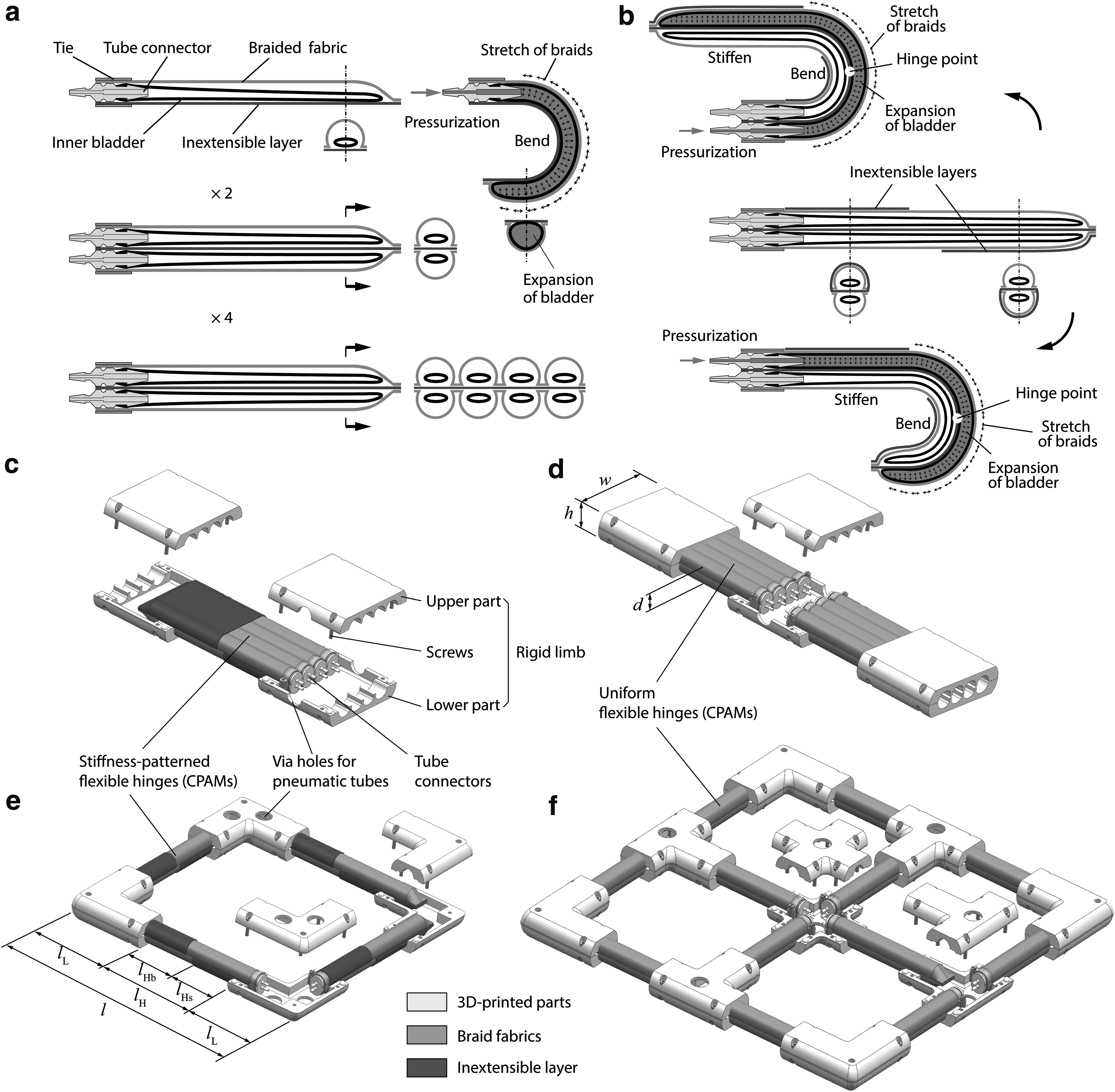
The proposed FifoBots perform flipping locomotion by folding and developing deformation. To achieve that, they are constructed with several flexible hinges and rigid limbs. The limbs are interconnected by the hinges and function as flanks of the fold. The hinges are made of bidirectional bending soft actuators, and their bending and stretching induce folding and developing deformation of the robots. With this deformation, the robots can vary their profiles and mass centers and thus realize flipping movement under the gravity force. With different numbers of limbs and hinges, the Single-Hinged FifoBot (SH-FifoBot) and the Double-Hinged FifoBot (DH-FifoBot) are designed. Their flipping movements are a little different, and their locomotion principles are presented in detail as follows.
The SH-FifoBot
The SH-FifoBot consists of only one hinge and two limbs, as shown in Figure 1a. The knack lies in the hinge that has variable hinge points. The hinge is made of a bidirectional bending soft actuator with stiffness patterned differently on its obverse and reverse sides, which allows it to bend nonsymmetrically. When the obverse side is actuated, the hinge bends toward the reverse side with the bending center (i.e., hinge point) closer to Limb 2 (Fig. 1a). When the reverse is actuated, the hinge bends toward the obverse with the hinge point closer to Limb 1. This characteristic of variable hinge points is essential for the SH-FifoBot to flip forward constantly.
Flipping locomotion principle of (a) the SH-FifoBot and (b) the DH-FifoBot, and their quadrilateral morphologies in (c) and (d), respectively. DH-FifoBot, double-hinged FifoBot; SH-FifoBot, single-hinged FifoBot.
One cycle of the flipping locomotion consists of two phases, that is, the folding phase ( and ) and the developing phase ( and ). During the folding phase, obverse side of the hinge is actuated to fold the robot and flip Limb 2 to below Limb 1. During the developing phase, the hinge is unactuated or reversely actuated to unfold the robot, in which Limb 1 is flipped forward because the mass center locates on the right of the supporting point (i.e., the lower left corner of Limb 2 in Fig. 1a).
To sum up, in a cycle, the SH-FifoBot first folds and then develops to the undeformed state again but flips by 180° (Fig. 1a). The step length S of the flipping locomotion is mainly made up of two portions: (1) the displacement caused by the crawling motion of Limb 2 during the folding phase, denoted as \documentclass{aastex}\usepackage{amsbsy}\usepackage{amsfonts}\usepackage{amssymb}\usepackage{bm}\usepackage{mathrsfs}\usepackage{pifont}\usepackage{stmaryrd}\usepackage{textcomp}\usepackage{portland, xspace}\usepackage{amsmath, amsxtra}\usepackage{upgreek}\pagestyle{empty}\DeclareMathSizes{10}{9}{7}{6}\begin{document}
$${S_{{ \rm{crawl1}}}}$$
\end{document} and (2) the displacement caused by the nonsymmetric folding of the robot, denoted as \documentclass{aastex}\usepackage{amsbsy}\usepackage{amsfonts}\usepackage{amssymb}\usepackage{bm}\usepackage{mathrsfs}\usepackage{pifont}\usepackage{stmaryrd}\usepackage{textcomp}\usepackage{portland, xspace}\usepackage{amsmath, amsxtra}\usepackage{upgreek}\pagestyle{empty}\DeclareMathSizes{10}{9}{7}{6}\begin{document}
$${S_{{ \rm{fold}}}}$$
\end{document}, as expressed in Equation (1). In the next cycle, the SH-FifoBot will flip by another step length and return to its original state (Fig. 1a).
\documentclass{aastex}\usepackage{amsbsy}\usepackage{amsfonts}\usepackage{amssymb}\usepackage{bm}\usepackage{mathrsfs}\usepackage{pifont}\usepackage{stmaryrd}\usepackage{textcomp}\usepackage{portland, xspace}\usepackage{amsmath, amsxtra}\usepackage{upgreek}\pagestyle{empty}\DeclareMathSizes{10}{9}{7}{6}\begin{document}
\begin{align*}
S = {S_{{ \rm{crawl1}}}} + {S_{{ \rm{fold}}}}. \tag{1}
\end{align*}
\end{document}
From the analysis above, we find that (1) the SH-FifoBot is actuated by only one bidirectional soft actuator and each side takes turn to be engaged only once or twice in a locomotion cycle, which indicates that the robot has compact structure and simple actuation system; (2) the flipping locomotion process does not require balance control, which simplifies the robot's control system; (3) most of the time during the locomotion, the SH-FifoBot contacts with the ground by the plain surface or the two parallel end edges of its limbs, which makes its movement more stable than previous rolling soft robots that have curved surface contact; (4) the stride of flipping locomotion is contributed by the folding deformation as well as the crawling motion, which can improve speed of the robot.
The DH-FifoBot
The SH-FifoBot can perform locomotion forward but not backward due to its nonsymmetric flexible hinge. However, backward movement is essential for the robot to avoid obstacles such as walls or gaps. Therefore, the DH-FifoBot is designed to perform bidirectional flipping locomotion, of course at the cost of more soft actuators. Even so, we have tried our best to make its structure as compact as possible.
Different from the SH-FifoBot, the DH-FifoBot has two flexible hinges and three rigid limbs, and each hinge is made of a bidirectional bending soft actuator with uniform stiffness, as shown in Figure 1b. Therefore, the hinge performs symmetric bending deformation and has unique hinge point (i.e., middle point of the hinge). Flipping locomotion cycle of the DH-FifoBot includes four phases, that is, the early folding ( and ), the later folding ( and ), the early developing ( and ), and the later developing ( and ).
During the folding phases, the robot folds at Hinge 2 and Hinge 1 successively, which is achieved by actuating obverse side of the hinges. This process is to flip Limb 3 to below Limb 2 and also move the robot's mass center above Limb 3. During the developing phases, Hinge 2 and Hinge 1 stretch, which is achieved by releasing obverse side or actuating reverse side of the hinges. This process flips Limb 1 and Limb 2 forward and thus unfolds the robot. It should be noted that in this cycle, Hinge 2 always bends or stretches in advance of Hinge 1, which ensures forward flipping movement of the robot. In the next cycle, the opposite is the case. If backward flipping motion is needed, then we can just reverse sequence of the two cycles. Similar to the SH-FifoBot, the step length of the DH-FifoBot also includes the displacements caused by the crawling motion (\documentclass{aastex}\usepackage{amsbsy}\usepackage{amsfonts}\usepackage{amssymb}\usepackage{bm}\usepackage{mathrsfs}\usepackage{pifont}\usepackage{stmaryrd}\usepackage{textcomp}\usepackage{portland, xspace}\usepackage{amsmath, amsxtra}\usepackage{upgreek}\pagestyle{empty}\DeclareMathSizes{10}{9}{7}{6}\begin{document}
$${S_{{ \rm{crawl1}}}}$$
\end{document}) and folding deformation (\documentclass{aastex}\usepackage{amsbsy}\usepackage{amsfonts}\usepackage{amssymb}\usepackage{bm}\usepackage{mathrsfs}\usepackage{pifont}\usepackage{stmaryrd}\usepackage{textcomp}\usepackage{portland, xspace}\usepackage{amsmath, amsxtra}\usepackage{upgreek}\pagestyle{empty}\DeclareMathSizes{10}{9}{7}{6}\begin{document}
$${S_{{ \rm{fold}}}}$$
\end{document}) but additionally contains a negative displacement (\documentclass{aastex}\usepackage{amsbsy}\usepackage{amsfonts}\usepackage{amssymb}\usepackage{bm}\usepackage{mathrsfs}\usepackage{pifont}\usepackage{stmaryrd}\usepackage{textcomp}\usepackage{portland, xspace}\usepackage{amsmath, amsxtra}\usepackage{upgreek}\pagestyle{empty}\DeclareMathSizes{10}{9}{7}{6}\begin{document}
$${S_{{ \rm{crawl2}}}}$$
\end{document}) due to the second backward crawling movement, as shown in Figure 1b and expressed in Equation (2).
\documentclass{aastex}\usepackage{amsbsy}\usepackage{amsfonts}\usepackage{amssymb}\usepackage{bm}\usepackage{mathrsfs}\usepackage{pifont}\usepackage{stmaryrd}\usepackage{textcomp}\usepackage{portland, xspace}\usepackage{amsmath, amsxtra}\usepackage{upgreek}\pagestyle{empty}\DeclareMathSizes{10}{9}{7}{6}\begin{document}
\begin{align*}
S = {S_{{ \rm{crawl1}}}} + {S_{{ \rm{fold}}}} + {S_{{ \rm{crawl2}}}}. \tag{2}
\end{align*}
\end{document}
Although the DH-FifoBot uses more soft actuators, it still has the characteristic of the SH-FifoBot, such as compact structure, simple actuation, free of balance control, and good stability.
The quadrilateral FifoBots
The SH-FifoBot and DH-FifoBot presented above have a linear morphology, which means that they can only move along a straight line. To reach every location on the ground, there are two methods, that is, the turning motion based on a parallel morphology52 and the biaxial motion based on a quadrilateral morphology.22 For the first one, its minimum turning radius may limit the maneuverability of the robots especially when it is required to change the moving direction immediately. Therefore, this research implements the quadrilateral one.
Figure 1c and d shows the proposed quadrilateral SH-FifoBot and DH-FifoBot, respectively. Different from the linear ones, the quadrilateral robots have their limbs arranged into two-dimensional arrays, that is, \documentclass{aastex}\usepackage{amsbsy}\usepackage{amsfonts}\usepackage{amssymb}\usepackage{bm}\usepackage{mathrsfs}\usepackage{pifont}\usepackage{stmaryrd}\usepackage{textcomp}\usepackage{portland, xspace}\usepackage{amsmath, amsxtra}\usepackage{upgreek}\pagestyle{empty}\DeclareMathSizes{10}{9}{7}{6}\begin{document}
$$2 \times 2$$
\end{document} or \documentclass{aastex}\usepackage{amsbsy}\usepackage{amsfonts}\usepackage{amssymb}\usepackage{bm}\usepackage{mathrsfs}\usepackage{pifont}\usepackage{stmaryrd}\usepackage{textcomp}\usepackage{portland, xspace}\usepackage{amsmath, amsxtra}\usepackage{upgreek}\pagestyle{empty}\DeclareMathSizes{10}{9}{7}{6}\begin{document}
$$3 \times 3$$
\end{document}. The rigid limbs are designed as L-shaped or cross-shaped and interconnected by the flexible hinges that are placed in two orthogonal directions. The hinges allow the robots to fold and develop in two directions and thus to perform the flipping movement in biaxial directions.
Locomotion Analysis
Besides the folding and developing phases, the flipping locomotion can also be decomposed into a succession of different movements: (1) the (static) crawling in the early and later folding phases, (2) the (dynamic) inverted-pendulum falling in the early folding phase, and (3) the (static or dynamic) rolling in the early and later developing phases. The static movement is achieved by and fully relies on the robot's deformation, which means that suspending the deformation can pause the movement at any time, supposing that the deformation rate is slow enough. The dynamic movement is governed by the gravity and inertia of the robot and cannot be retarded by slowing or stopping the robot's deformation. This section is aimed to explore the parameters' influence on the FifoBots' performances in different movements and validate the proposed flipping locomotion in theory.
The deformation
The SH-FifoBot and DH-FifoBot are simplified as a multisegment C1 curve without thickness in the vertical plane (Fig. 2). The robot's deformation is characterized by the curvature varying with the arc length along the curve and the time, that is, \documentclass{aastex}\usepackage{amsbsy}\usepackage{amsfonts}\usepackage{amssymb}\usepackage{bm}\usepackage{mathrsfs}\usepackage{pifont}\usepackage{stmaryrd}\usepackage{textcomp}\usepackage{portland, xspace}\usepackage{amsmath, amsxtra}\usepackage{upgreek}\pagestyle{empty}\DeclareMathSizes{10}{9}{7}{6}\begin{document}
$$\bar \kappa ( \bar s , \bar t )$$
\end{document} in Equations (3) and (4), supposing the hinges flex with uniform curvature \documentclass{aastex}\usepackage{amsbsy}\usepackage{amsfonts}\usepackage{amssymb}\usepackage{bm}\usepackage{mathrsfs}\usepackage{pifont}\usepackage{stmaryrd}\usepackage{textcomp}\usepackage{portland, xspace}\usepackage{amsmath, amsxtra}\usepackage{upgreek}\pagestyle{empty}\DeclareMathSizes{10}{9}{7}{6}\begin{document}
$${ \bar \kappa _1}$$
\end{document} and \documentclass{aastex}\usepackage{amsbsy}\usepackage{amsfonts}\usepackage{amssymb}\usepackage{bm}\usepackage{mathrsfs}\usepackage{pifont}\usepackage{stmaryrd}\usepackage{textcomp}\usepackage{portland, xspace}\usepackage{amsmath, amsxtra}\usepackage{upgreek}\pagestyle{empty}\DeclareMathSizes{10}{9}{7}{6}\begin{document}
$${ \bar \kappa _2}$$
\end{document}. The FifoBots' linear density also varies with the arc length, that is, \documentclass{aastex}\usepackage{amsbsy}\usepackage{amsfonts}\usepackage{amssymb}\usepackage{bm}\usepackage{mathrsfs}\usepackage{pifont}\usepackage{stmaryrd}\usepackage{textcomp}\usepackage{portland, xspace}\usepackage{amsmath, amsxtra}\usepackage{upgreek}\pagestyle{empty}\DeclareMathSizes{10}{9}{7}{6}\begin{document}
$$\bar \rho ( \bar s )$$
\end{document} in Equations (3) and (4) assuming the hinges and limbs to be uniform beams. All variables with an upper bar (Table 1) have been nondimensionalized by setting the robot's total length l as the unit length, the total mass m as the unit mass, and the time constant \documentclass{aastex}\usepackage{amsbsy}\usepackage{amsfonts}\usepackage{amssymb}\usepackage{bm}\usepackage{mathrsfs}\usepackage{pifont}\usepackage{stmaryrd}\usepackage{textcomp}\usepackage{portland, xspace}\usepackage{amsmath, amsxtra}\usepackage{upgreek}\pagestyle{empty}\DeclareMathSizes{10}{9}{7}{6}\begin{document}
$$\sqrt {l / g}$$
\end{document} as the unit time.
The crawling and falling movements of (a) the SH-FifoBot and (b) the DH-FifoBot during the folding phases.
The variables with an upper bar are dimensionless, obtained by scaling the dimensional variables by the robot's total mass m, the total length l, and the time constant \documentclass{aastex}\usepackage{amsbsy}\usepackage{amsfonts}\usepackage{amssymb}\usepackage{bm}\usepackage{mathrsfs}\usepackage{pifont}\usepackage{stmaryrd}\usepackage{textcomp}\usepackage{portland, xspace}\usepackage{amsmath, amsxtra}\usepackage{upgreek}\pagestyle{empty}\DeclareMathSizes{10}{9}{7}{6}\begin{document}
$$\sqrt {l / g}$$
\end{document}.
Setting a body reference xoy for the FifoBots with the origin located at \documentclass{aastex}\usepackage{amsbsy}\usepackage{amsfonts}\usepackage{amssymb}\usepackage{bm}\usepackage{mathrsfs}\usepackage{pifont}\usepackage{stmaryrd}\usepackage{textcomp}\usepackage{portland, xspace}\usepackage{amsmath, amsxtra}\usepackage{upgreek}\pagestyle{empty}\DeclareMathSizes{10}{9}{7}{6}\begin{document}
$$\bar s = 0$$
\end{document} and x-axis aligned with the proximal limb, the deflection angle (\documentclass{aastex}\usepackage{amsbsy}\usepackage{amsfonts}\usepackage{amssymb}\usepackage{bm}\usepackage{mathrsfs}\usepackage{pifont}\usepackage{stmaryrd}\usepackage{textcomp}\usepackage{portland, xspace}\usepackage{amsmath, amsxtra}\usepackage{upgreek}\pagestyle{empty}\DeclareMathSizes{10}{9}{7}{6}\begin{document}
$$\theta$$
\end{document}) and point location (\documentclass{aastex}\usepackage{amsbsy}\usepackage{amsfonts}\usepackage{amssymb}\usepackage{bm}\usepackage{mathrsfs}\usepackage{pifont}\usepackage{stmaryrd}\usepackage{textcomp}\usepackage{portland, xspace}\usepackage{amsmath, amsxtra}\usepackage{upgreek}\pagestyle{empty}\DeclareMathSizes{10}{9}{7}{6}\begin{document}
$${ \bar {\bf r}}$$
\end{document}) along the curve are determined according to the differential geometry mathematics53 [Eqs. (5) and (6)]. The mass center (\documentclass{aastex}\usepackage{amsbsy}\usepackage{amsfonts}\usepackage{amssymb}\usepackage{bm}\usepackage{mathrsfs}\usepackage{pifont}\usepackage{stmaryrd}\usepackage{textcomp}\usepackage{portland, xspace}\usepackage{amsmath, amsxtra}\usepackage{upgreek}\pagestyle{empty}\DeclareMathSizes{10}{9}{7}{6}\begin{document}
$${{ \bar{ \bf r}}_{ \rm{c}}}$$
\end{document}) and the gyration radius (\documentclass{aastex}\usepackage{amsbsy}\usepackage{amsfonts}\usepackage{amssymb}\usepackage{bm}\usepackage{mathrsfs}\usepackage{pifont}\usepackage{stmaryrd}\usepackage{textcomp}\usepackage{portland, xspace}\usepackage{amsmath, amsxtra}\usepackage{upgreek}\pagestyle{empty}\DeclareMathSizes{10}{9}{7}{6}\begin{document}
$${r_{ \rm{g}}}$$
\end{document} or \documentclass{aastex}\usepackage{amsbsy}\usepackage{amsfonts}\usepackage{amssymb}\usepackage{bm}\usepackage{mathrsfs}\usepackage{pifont}\usepackage{stmaryrd}\usepackage{textcomp}\usepackage{portland, xspace}\usepackage{amsmath, amsxtra}\usepackage{upgreek}\pagestyle{empty}\DeclareMathSizes{10}{9}{7}{6}\begin{document}
$${r_{{ \rm{gc}}}}$$
\end{document}, with respect to the origin or the mass center) are calculated according to Equations (7)–(9). The variation rates of the curvature, the deflection angle, and the point coordinates with respect to the time are derived from the actuation speed of the flexible hinges (i.e., \documentclass{aastex}\usepackage{amsbsy}\usepackage{amsfonts}\usepackage{amssymb}\usepackage{bm}\usepackage{mathrsfs}\usepackage{pifont}\usepackage{stmaryrd}\usepackage{textcomp}\usepackage{portland, xspace}\usepackage{amsmath, amsxtra}\usepackage{upgreek}\pagestyle{empty}\DeclareMathSizes{10}{9}{7}{6}\begin{document}
$${ \rm{d}}{ \bar \kappa _1} / { \rm{d}} \bar t$$
\end{document} and \documentclass{aastex}\usepackage{amsbsy}\usepackage{amsfonts}\usepackage{amssymb}\usepackage{bm}\usepackage{mathrsfs}\usepackage{pifont}\usepackage{stmaryrd}\usepackage{textcomp}\usepackage{portland, xspace}\usepackage{amsmath, amsxtra}\usepackage{upgreek}\pagestyle{empty}\DeclareMathSizes{10}{9}{7}{6}\begin{document}
$${ \rm{d}}{ \bar \kappa _2} / { \rm{d}} \bar t$$
\end{document}) according to Appendix Equations (A1)–(A9).
\documentclass{aastex}\usepackage{amsbsy}\usepackage{amsfonts}\usepackage{amssymb}\usepackage{bm}\usepackage{mathrsfs}\usepackage{pifont}\usepackage{stmaryrd}\usepackage{textcomp}\usepackage{portland, xspace}\usepackage{amsmath, amsxtra}\usepackage{upgreek}\pagestyle{empty}\DeclareMathSizes{10}{9}{7}{6}\begin{document}
\begin{align*}
\theta ( \bar s , \bar t ) = \int_0^{ \bar s} \bar \kappa ( \bar s , \bar t ) { \rm{d}} \bar s , \tag{5}
\end{align*}
\end{document}
\documentclass{aastex}\usepackage{amsbsy}\usepackage{amsfonts}\usepackage{amssymb}\usepackage{bm}\usepackage{mathrsfs}\usepackage{pifont}\usepackage{stmaryrd}\usepackage{textcomp}\usepackage{portland, xspace}\usepackage{amsmath, amsxtra}\usepackage{upgreek}\pagestyle{empty}\DeclareMathSizes{10}{9}{7}{6}\begin{document}
\begin{align*}
{ \bar{ \bf r}} ( \bar s , \bar t ) = \int_0^{ \bar s} [ \cos \theta ( \bar s , \bar t ) , \; \sin \theta ( \bar s , \bar t ) ] { \rm{d}} \bar s , \tag{6}
\end{align*}
\end{document}\documentclass{aastex}\usepackage{amsbsy}\usepackage{amsfonts}\usepackage{amssymb}\usepackage{bm}\usepackage{mathrsfs}\usepackage{pifont}\usepackage{stmaryrd}\usepackage{textcomp}\usepackage{portland, xspace}\usepackage{amsmath, amsxtra}\usepackage{upgreek}\pagestyle{empty}\DeclareMathSizes{10}{9}{7}{6}\begin{document}
\begin{align*}
{{ \bar{ \bf r}}_{ \rm{c}}} ( \bar t ) = \int_0^1 { \bar { \bf r}} ( \bar s , \bar t ) \bar \rho ( \bar s ) { \rm{d}} \bar s , \tag{7}
\end{align*}
\end{document}\documentclass{aastex}\usepackage{amsbsy}\usepackage{amsfonts}\usepackage{amssymb}\usepackage{bm}\usepackage{mathrsfs}\usepackage{pifont}\usepackage{stmaryrd}\usepackage{textcomp}\usepackage{portland, xspace}\usepackage{amsmath, amsxtra}\usepackage{upgreek}\pagestyle{empty}\DeclareMathSizes{10}{9}{7}{6}\begin{document}
\begin{align*}
{ \bar r_{ \rm{g}}} ( \bar t ) = \sqrt { \int_0^1 \parallel { \bar { \bf r}} ( \bar s , \bar t ) { \parallel ^2} \bar \rho ( \bar s ) { \rm{d}} \bar s} , \tag{8}
\end{align*}
\end{document}\documentclass{aastex}\usepackage{amsbsy}\usepackage{amsfonts}\usepackage{amssymb}\usepackage{bm}\usepackage{mathrsfs}\usepackage{pifont}\usepackage{stmaryrd}\usepackage{textcomp}\usepackage{portland, xspace}\usepackage{amsmath, amsxtra}\usepackage{upgreek}\pagestyle{empty}\DeclareMathSizes{10}{9}{7}{6}\begin{document}
\begin{align*}
{ \bar r_{{ \rm{gc}}}} ( \bar t ) = \sqrt {{{ \bar r}_{ \rm{g}}}{{ ( \bar t ) }^2} - \parallel {{{ \bar{ \bf r}}}_{ \rm{c}}} ( \bar t ) { \parallel ^2}}. \tag{9}
\end{align*}
\end{document}
The crawling movements
In nature, the inchworm sequentially anchors its front and rear legs on the ground as its body bends and stretches to perform the crawling stride and move the body forward constantly.54 Inspired by the inchworm, the FifoBots exploit the rear and front ends to imitate the front and rear legs, and the active flexible hinges to imitate the bendable body of the inchworm. Different from the inchworm and most inchworm-inspired soft robots,22,23,47,54–62 the FifoBots perform the crawling movement only in the bending (or folding) phase (Fig. 2a, b– or , , and and b–), and in the stretching (or developing) phase, the robot switches into the other aforementioned movement patterns (such as the rolling movement), which avoids the backlash crawling displacement and thus improves the moving efficiency. The SH-FifoBot and DH-FifoBot share the process of the crawling and falling movements during the (early) folding phase, that is, the Crawling 1 (i.e., the process of – in Case 1 or , , and in Case 2) and the Falling (i.e., the process of –) in Figure 2. The DH-FifoBot performs an additional crawling movement in the later folding phase, that is, the Crawling 2 (i.e., the process of b–).
During the crawling movements, the rear and front ends of the robot (in Crawling 1) or the rear end of the robot and the proximal end of the front limb (in Crawling 2) contact with the ground, and the robot's mass center is located between the two contact points along the horizontal direction. Relying on variation of the span between the front and rear contact points [Eqs. (10) and (11)] and the location of the mass center [Eq. (12)], the crawling movement is achieved.
Two possible cases occur at the end of Crawling 1 (Fig. 2a, b). In Case 1, the crawling movement terminates when the mass center surmounts the front contact point (Fig. 2a, b), and then, the robot switches into the falling movement (–). In Case 2, the mass center never surmounts the front contact point even when the front limb (i.e., Limb 2 of the SH-FifoBot or Limb 3 of the DH-FifoBot) has fallen down on the ground (Fig. 2a, b), not followed by the falling movement any more, which disables further movement of the SH-FifoBot but has little influence on further movement of the DH-FifoBot because the DH-FifoBot can perform a second crawling movement (i.e., Crawling 2 in Fig. 2b) in the later folding phase to shift forward its mass center further to surmount the front contact point through flexion of the rear hinge (i.e., Hinge 1). Whether Crawling 1 acts as Case 1 or Case 2 depends on the geometry and mass parameters of the FifoBots, more specifically the length ratio (\documentclass{aastex}\usepackage{amsbsy}\usepackage{amsfonts}\usepackage{amssymb}\usepackage{bm}\usepackage{mathrsfs}\usepackage{pifont}\usepackage{stmaryrd}\usepackage{textcomp}\usepackage{portland, xspace}\usepackage{amsmath, amsxtra}\usepackage{upgreek}\pagestyle{empty}\DeclareMathSizes{10}{9}{7}{6}\begin{document}
$${ \bar l_{ \rm{H}}} / { \bar l_{ \rm{L}}}$$
\end{document}) and density ratio (\documentclass{aastex}\usepackage{amsbsy}\usepackage{amsfonts}\usepackage{amssymb}\usepackage{bm}\usepackage{mathrsfs}\usepackage{pifont}\usepackage{stmaryrd}\usepackage{textcomp}\usepackage{portland, xspace}\usepackage{amsmath, amsxtra}\usepackage{upgreek}\pagestyle{empty}\DeclareMathSizes{10}{9}{7}{6}\begin{document}
$${ \bar \rho _{ \rm{H}}} / { \bar \rho _{ \rm{L}}}$$
\end{document}) of hinge to limb, and the stiffened length ratio of the SH-FifoBot's hinge (\documentclass{aastex}\usepackage{amsbsy}\usepackage{amsfonts}\usepackage{amssymb}\usepackage{bm}\usepackage{mathrsfs}\usepackage{pifont}\usepackage{stmaryrd}\usepackage{textcomp}\usepackage{portland, xspace}\usepackage{amsmath, amsxtra}\usepackage{upgreek}\pagestyle{empty}\DeclareMathSizes{10}{9}{7}{6}\begin{document}
$${ \bar l_{{ \rm{Hs}}}} / { \bar l_{ \rm{H}}}$$
\end{document}). Generally, Case 1 results from small \documentclass{aastex}\usepackage{amsbsy}\usepackage{amsfonts}\usepackage{amssymb}\usepackage{bm}\usepackage{mathrsfs}\usepackage{pifont}\usepackage{stmaryrd}\usepackage{textcomp}\usepackage{portland, xspace}\usepackage{amsmath, amsxtra}\usepackage{upgreek}\pagestyle{empty}\DeclareMathSizes{10}{9}{7}{6}\begin{document}
$${ \bar l_{ \rm{H}}} / { \bar l_{ \rm{L}}}$$
\end{document}, whereas Case 2 arises with large \documentclass{aastex}\usepackage{amsbsy}\usepackage{amsfonts}\usepackage{amssymb}\usepackage{bm}\usepackage{mathrsfs}\usepackage{pifont}\usepackage{stmaryrd}\usepackage{textcomp}\usepackage{portland, xspace}\usepackage{amsmath, amsxtra}\usepackage{upgreek}\pagestyle{empty}\DeclareMathSizes{10}{9}{7}{6}\begin{document}
$${ \bar l_{ \rm{H}}} / { \bar l_{ \rm{L}}}$$
\end{document}, and the details will be presented in the following discussions.
The duration time of Crawling 1 in Case 1 [denoted as \documentclass{aastex}\usepackage{amsbsy}\usepackage{amsfonts}\usepackage{amssymb}\usepackage{bm}\usepackage{mathrsfs}\usepackage{pifont}\usepackage{stmaryrd}\usepackage{textcomp}\usepackage{portland, xspace}\usepackage{amsmath, amsxtra}\usepackage{upgreek}\pagestyle{empty}\DeclareMathSizes{10}{9}{7}{6}\begin{document}
$${ \bar t \prime _{{ \rm{crawl1}}}}$$
\end{document} in Eq. (13)] is shorter than that in Case 2 [denoted as \documentclass{aastex}\usepackage{amsbsy}\usepackage{amsfonts}\usepackage{amssymb}\usepackage{bm}\usepackage{mathrsfs}\usepackage{pifont}\usepackage{stmaryrd}\usepackage{textcomp}\usepackage{portland, xspace}\usepackage{amsmath, amsxtra}\usepackage{upgreek}\pagestyle{empty}\DeclareMathSizes{10}{9}{7}{6}\begin{document}
$${ \bar t \prime _{{ \rm{crawl1}}}}$$
\end{document} in Eq. (13)] by the time of the process from to . To ensure the same initial state of Crawling 2 after Crawling 1, we let the robot continue to fold its front hinge at the end of the falling movement in Case 1 until the robot reaches the same final state with Case 2, that is, the process from to . During the Crawling 2, the DH-FifoBot keeps its front limb (i.e., Limb 3) horizontal while the rear end slides on the ground, achieved by coordinated flexion of the two hinges. Crawling 2 terminates when the rear and front contact points coincide (Fig. 2b), and the duration time is calculated by Equation (13).
where \documentclass{aastex}\usepackage{amsbsy}\usepackage{amsfonts}\usepackage{amssymb}\usepackage{bm}\usepackage{mathrsfs}\usepackage{pifont}\usepackage{stmaryrd}\usepackage{textcomp}\usepackage{portland, xspace}\usepackage{amsmath, amsxtra}\usepackage{upgreek}\pagestyle{empty}\DeclareMathSizes{10}{9}{7}{6}\begin{document}
$${ \rm{arg}} ( )$$
\end{document} is a function returning the argument of a vector in R2.
The duration time \documentclass{aastex}\usepackage{amsbsy}\usepackage{amsfonts}\usepackage{amssymb}\usepackage{bm}\usepackage{mathrsfs}\usepackage{pifont}\usepackage{stmaryrd}\usepackage{textcomp}\usepackage{portland, xspace}\usepackage{amsmath, amsxtra}\usepackage{upgreek}\pagestyle{empty}\DeclareMathSizes{10}{9}{7}{6}\begin{document}
$${ \bar t_{{ \rm{crawl}}}}$$
\end{document} depends on the actuation speed (i.e., \documentclass{aastex}\usepackage{amsbsy}\usepackage{amsfonts}\usepackage{amssymb}\usepackage{bm}\usepackage{mathrsfs}\usepackage{pifont}\usepackage{stmaryrd}\usepackage{textcomp}\usepackage{portland, xspace}\usepackage{amsmath, amsxtra}\usepackage{upgreek}\pagestyle{empty}\DeclareMathSizes{10}{9}{7}{6}\begin{document}
$${ \rm{d}}{ \bar \kappa _1} / { \rm{d}} \bar t$$
\end{document} and/or \documentclass{aastex}\usepackage{amsbsy}\usepackage{amsfonts}\usepackage{amssymb}\usepackage{bm}\usepackage{mathrsfs}\usepackage{pifont}\usepackage{stmaryrd}\usepackage{textcomp}\usepackage{portland, xspace}\usepackage{amsmath, amsxtra}\usepackage{upgreek}\pagestyle{empty}\DeclareMathSizes{10}{9}{7}{6}\begin{document}
$${ \rm{d}}{ \bar \kappa _2} / { \rm{d}} \bar t$$
\end{document}). For comparability of the crawling time with different parameters, the actuation speed is set as the reciprocal of the hinge length [Eqs. (14) and (15)], an intuitive relationship based on the fact that the longer hinge needs more pressurization time to flex into the same curvature. The crawling time exhibited by the robot with different \documentclass{aastex}\usepackage{amsbsy}\usepackage{amsfonts}\usepackage{amssymb}\usepackage{bm}\usepackage{mathrsfs}\usepackage{pifont}\usepackage{stmaryrd}\usepackage{textcomp}\usepackage{portland, xspace}\usepackage{amsmath, amsxtra}\usepackage{upgreek}\pagestyle{empty}\DeclareMathSizes{10}{9}{7}{6}\begin{document}
$${ \bar l_{ \rm{H}}} / { \bar l_{ \rm{L}}}$$
\end{document}, \documentclass{aastex}\usepackage{amsbsy}\usepackage{amsfonts}\usepackage{amssymb}\usepackage{bm}\usepackage{mathrsfs}\usepackage{pifont}\usepackage{stmaryrd}\usepackage{textcomp}\usepackage{portland, xspace}\usepackage{amsmath, amsxtra}\usepackage{upgreek}\pagestyle{empty}\DeclareMathSizes{10}{9}{7}{6}\begin{document}
$${ \bar \rho _{ \rm{H}}} / { \bar \rho _{ \rm{L}}}$$
\end{document}, and/or \documentclass{aastex}\usepackage{amsbsy}\usepackage{amsfonts}\usepackage{amssymb}\usepackage{bm}\usepackage{mathrsfs}\usepackage{pifont}\usepackage{stmaryrd}\usepackage{textcomp}\usepackage{portland, xspace}\usepackage{amsmath, amsxtra}\usepackage{upgreek}\pagestyle{empty}\DeclareMathSizes{10}{9}{7}{6}\begin{document}
$${ \bar l_{{ \rm{Hs}}}} / { \bar l_{ \rm{H}}}$$
\end{document} is calculated by Equations (3)–(13).
\documentclass{aastex}\usepackage{amsbsy}\usepackage{amsfonts}\usepackage{amssymb}\usepackage{bm}\usepackage{mathrsfs}\usepackage{pifont}\usepackage{stmaryrd}\usepackage{textcomp}\usepackage{portland, xspace}\usepackage{amsmath, amsxtra}\usepackage{upgreek}\pagestyle{empty}\DeclareMathSizes{10}{9}{7}{6}\begin{document}
\begin{align*}
{ \rm { The } } \; { \rm { SH } } - { \rm { FifoBot: } } \; { \frac { { \rm { d } } { { \bar \kappa } _1 } ( \bar t ) } { { \rm { d } } \bar t } } \equiv \frac { 1 } { { { { \bar l } _ { \rm { H } } } } } , \tag { 14 }
\end{align*}
\end{document}
Due to the gravity, the normal [Eqs. (16) and (17)] and frictional [Eqs. (18) and (19)] forces are exerted on the rear and front contact points of the robot. The frictional coefficients (\documentclass{aastex}\usepackage{amsbsy}\usepackage{amsfonts}\usepackage{amssymb}\usepackage{bm}\usepackage{mathrsfs}\usepackage{pifont}\usepackage{stmaryrd}\usepackage{textcomp}\usepackage{portland, xspace}\usepackage{amsmath, amsxtra}\usepackage{upgreek}\pagestyle{empty}\DeclareMathSizes{10}{9}{7}{6}\begin{document}
$${ \mu _{ \rm{f}}}$$
\end{document} and \documentclass{aastex}\usepackage{amsbsy}\usepackage{amsfonts}\usepackage{amssymb}\usepackage{bm}\usepackage{mathrsfs}\usepackage{pifont}\usepackage{stmaryrd}\usepackage{textcomp}\usepackage{portland, xspace}\usepackage{amsmath, amsxtra}\usepackage{upgreek}\pagestyle{empty}\DeclareMathSizes{10}{9}{7}{6}\begin{document}
$${ \mu _{ \rm{r}}}$$
\end{document}) depend on the sliding velocities [Eqs. (20) and (21)], in which the static and kinematic Coulomb frictional coefficients (\documentclass{aastex}\usepackage{amsbsy}\usepackage{amsfonts}\usepackage{amssymb}\usepackage{bm}\usepackage{mathrsfs}\usepackage{pifont}\usepackage{stmaryrd}\usepackage{textcomp}\usepackage{portland, xspace}\usepackage{amsmath, amsxtra}\usepackage{upgreek}\pagestyle{empty}\DeclareMathSizes{10}{9}{7}{6}\begin{document}
$${ \mu _{{ \rm{Ls}}}}$$
\end{document} and \documentclass{aastex}\usepackage{amsbsy}\usepackage{amsfonts}\usepackage{amssymb}\usepackage{bm}\usepackage{mathrsfs}\usepackage{pifont}\usepackage{stmaryrd}\usepackage{textcomp}\usepackage{portland, xspace}\usepackage{amsmath, amsxtra}\usepackage{upgreek}\pagestyle{empty}\DeclareMathSizes{10}{9}{7}{6}\begin{document}
$${ \mu _{{ \rm{Lk}}}}$$
\end{document}) are considered. As the span distance varies (i.e., \documentclass{aastex}\usepackage{amsbsy}\usepackage{amsfonts}\usepackage{amssymb}\usepackage{bm}\usepackage{mathrsfs}\usepackage{pifont}\usepackage{stmaryrd}\usepackage{textcomp}\usepackage{portland, xspace}\usepackage{amsmath, amsxtra}\usepackage{upgreek}\pagestyle{empty}\DeclareMathSizes{10}{9}{7}{6}\begin{document}
$${ \rm{d}}{ \bar d_{ \rm{s}}} / { \rm{d}} \bar t \ne 0$$
\end{document}), the contact point (front or rear) with lower frictional force moves while the other point keeps stationary [Eq. (22)]. Substituting Equations (16)–(19) into it yields Equation (23), which associates the crawling movement with the mass center's location (or the robot's deformation) and the frictional coefficients directly. Stopping the deformation (i.e., let \documentclass{aastex}\usepackage{amsbsy}\usepackage{amsfonts}\usepackage{amssymb}\usepackage{bm}\usepackage{mathrsfs}\usepackage{pifont}\usepackage{stmaryrd}\usepackage{textcomp}\usepackage{portland, xspace}\usepackage{amsmath, amsxtra}\usepackage{upgreek}\pagestyle{empty}\DeclareMathSizes{10}{9}{7}{6}\begin{document}
$${ \rm{d}}{ \bar d_{ \rm{s}}} / { \rm{d}} \bar t = 0$$
\end{document}) would halt the movement (i.e., \documentclass{aastex}\usepackage{amsbsy}\usepackage{amsfonts}\usepackage{amssymb}\usepackage{bm}\usepackage{mathrsfs}\usepackage{pifont}\usepackage{stmaryrd}\usepackage{textcomp}\usepackage{portland, xspace}\usepackage{amsmath, amsxtra}\usepackage{upgreek}\pagestyle{empty}\DeclareMathSizes{10}{9}{7}{6}\begin{document}
$${ \rm{d}}{ \bar x_{ \rm{r}}} / { \rm{d}} \bar t = 0$$
\end{document}, \documentclass{aastex}\usepackage{amsbsy}\usepackage{amsfonts}\usepackage{amssymb}\usepackage{bm}\usepackage{mathrsfs}\usepackage{pifont}\usepackage{stmaryrd}\usepackage{textcomp}\usepackage{portland, xspace}\usepackage{amsmath, amsxtra}\usepackage{upgreek}\pagestyle{empty}\DeclareMathSizes{10}{9}{7}{6}\begin{document}
$${ \rm{d}}{ \bar x_{ \rm{f}}} / { \rm{d}} \bar t = 0$$
\end{document}), which means that the crawling movement is a static process.
\documentclass{aastex}\usepackage{amsbsy}\usepackage{amsfonts}\usepackage{amssymb}\usepackage{bm}\usepackage{mathrsfs}\usepackage{pifont}\usepackage{stmaryrd}\usepackage{textcomp}\usepackage{portland, xspace}\usepackage{amsmath, amsxtra}\usepackage{upgreek}\pagestyle{empty}\DeclareMathSizes{10}{9}{7}{6}\begin{document}
\begin{align*}
{ \bar N_{ \rm{r}}} = 1 - \left( {{{ \bar d}_{ \rm{c}}} / {{ \bar d}_{ \rm{s}}}} \right) , \tag{16}
\end{align*}
\end{document}
The sliding velocity of the rear contact point is nonnegative while that of the front contact point is nonpositive [implied by Eq. (23)] because the span distance between the front and rear contact points keeps decreasing during the folding phase. The crawling displacement depicted in Figure 1 is determined by Equation (24). To enhance the forward crawling (i.e., Crawling 1) as well as inhibit the backward crawling (i.e., Crawling 2), it is preferred to enlarge the frictional force at the front contact point by designing the FifoBots' parameters to make \documentclass{aastex}\usepackage{amsbsy}\usepackage{amsfonts}\usepackage{amssymb}\usepackage{bm}\usepackage{mathrsfs}\usepackage{pifont}\usepackage{stmaryrd}\usepackage{textcomp}\usepackage{portland, xspace}\usepackage{amsmath, amsxtra}\usepackage{upgreek}\pagestyle{empty}\DeclareMathSizes{10}{9}{7}{6}\begin{document}
$${ \bar d_{ \rm{c}}}$$
\end{document} closer to \documentclass{aastex}\usepackage{amsbsy}\usepackage{amsfonts}\usepackage{amssymb}\usepackage{bm}\usepackage{mathrsfs}\usepackage{pifont}\usepackage{stmaryrd}\usepackage{textcomp}\usepackage{portland, xspace}\usepackage{amsmath, amsxtra}\usepackage{upgreek}\pagestyle{empty}\DeclareMathSizes{10}{9}{7}{6}\begin{document}
$${ \bar d_{ \rm{s}}}$$
\end{document}.
In addition to the parameters \documentclass{aastex}\usepackage{amsbsy}\usepackage{amsfonts}\usepackage{amssymb}\usepackage{bm}\usepackage{mathrsfs}\usepackage{pifont}\usepackage{stmaryrd}\usepackage{textcomp}\usepackage{portland, xspace}\usepackage{amsmath, amsxtra}\usepackage{upgreek}\pagestyle{empty}\DeclareMathSizes{10}{9}{7}{6}\begin{document}
$${ \bar l_{ \rm{H}}} / { \bar l_{ \rm{L}}}$$
\end{document}, \documentclass{aastex}\usepackage{amsbsy}\usepackage{amsfonts}\usepackage{amssymb}\usepackage{bm}\usepackage{mathrsfs}\usepackage{pifont}\usepackage{stmaryrd}\usepackage{textcomp}\usepackage{portland, xspace}\usepackage{amsmath, amsxtra}\usepackage{upgreek}\pagestyle{empty}\DeclareMathSizes{10}{9}{7}{6}\begin{document}
$${ \bar \rho _{ \rm{H}}} / { \bar \rho _{ \rm{L}}}$$
\end{document}, and \documentclass{aastex}\usepackage{amsbsy}\usepackage{amsfonts}\usepackage{amssymb}\usepackage{bm}\usepackage{mathrsfs}\usepackage{pifont}\usepackage{stmaryrd}\usepackage{textcomp}\usepackage{portland, xspace}\usepackage{amsmath, amsxtra}\usepackage{upgreek}\pagestyle{empty}\DeclareMathSizes{10}{9}{7}{6}\begin{document}
$${ \bar l_{{ \rm{Hs}}}} / { \bar l_{ \rm{H}}}$$
\end{document}, the coefficient ratio of the kinematic to the static friction (\documentclass{aastex}\usepackage{amsbsy}\usepackage{amsfonts}\usepackage{amssymb}\usepackage{bm}\usepackage{mathrsfs}\usepackage{pifont}\usepackage{stmaryrd}\usepackage{textcomp}\usepackage{portland, xspace}\usepackage{amsmath, amsxtra}\usepackage{upgreek}\pagestyle{empty}\DeclareMathSizes{10}{9}{7}{6}\begin{document}
$${ \mu _{{ \rm{Lk}}}} / { \mu _{{ \rm{Ls}}}}$$
\end{document}) between the limb and ground can also affects the crawling displacement. At the beginning of the crawling movement, the robot lying on the ground (Fig. 2a, b) is supported by its two end points with Hinge 1 (for the SH-FifoBot) or Hinge 2 (for the DH-FifoBot) flexed slightly. The equal static frictional forces produced by the equal normal forces at the two end points make it uncertain, which of the ends moves first at the beginning. Supposing the front end slides first due to a disturbance, the rear end would keep stationary until the mass center deviates from the middle to the right by a certain distance evaluated as \documentclass{aastex}\usepackage{amsbsy}\usepackage{amsfonts}\usepackage{amssymb}\usepackage{bm}\usepackage{mathrsfs}\usepackage{pifont}\usepackage{stmaryrd}\usepackage{textcomp}\usepackage{portland, xspace}\usepackage{amsmath, amsxtra}\usepackage{upgreek}\pagestyle{empty}\DeclareMathSizes{10}{9}{7}{6}\begin{document}
$$( 1 - { \mu _{{ \rm{Lk}}}} / { \mu _{{ \rm{Ls}}}} ) / ( 2 + 2{ \mu _{{ \rm{Lk}}}} / { \mu _{{ \rm{Ls}}}} )$$
\end{document} according to Equation (23) and Equations (20) and (21). If the rear end moves first, the front end would maintain anchoring on the ground throughout the crawling because the mass center seems impossible to move left upon folding of the robot (Fig. 2).
The above Equations (3)–(24) imply an association between the crawling performances (\documentclass{aastex}\usepackage{amsbsy}\usepackage{amsfonts}\usepackage{amssymb}\usepackage{bm}\usepackage{mathrsfs}\usepackage{pifont}\usepackage{stmaryrd}\usepackage{textcomp}\usepackage{portland, xspace}\usepackage{amsmath, amsxtra}\usepackage{upgreek}\pagestyle{empty}\DeclareMathSizes{10}{9}{7}{6}\begin{document}
$${ \bar t_{{ \rm{crawl}}}}$$
\end{document} and \documentclass{aastex}\usepackage{amsbsy}\usepackage{amsfonts}\usepackage{amssymb}\usepackage{bm}\usepackage{mathrsfs}\usepackage{pifont}\usepackage{stmaryrd}\usepackage{textcomp}\usepackage{portland, xspace}\usepackage{amsmath, amsxtra}\usepackage{upgreek}\pagestyle{empty}\DeclareMathSizes{10}{9}{7}{6}\begin{document}
$${ \bar S_{{ \rm{crawl}}}}$$
\end{document}) and the FifoBots' parameters (\documentclass{aastex}\usepackage{amsbsy}\usepackage{amsfonts}\usepackage{amssymb}\usepackage{bm}\usepackage{mathrsfs}\usepackage{pifont}\usepackage{stmaryrd}\usepackage{textcomp}\usepackage{portland, xspace}\usepackage{amsmath, amsxtra}\usepackage{upgreek}\pagestyle{empty}\DeclareMathSizes{10}{9}{7}{6}\begin{document}
$${ \bar l_{ \rm{H}}} / { \bar l_{ \rm{L}}}$$
\end{document}, \documentclass{aastex}\usepackage{amsbsy}\usepackage{amsfonts}\usepackage{amssymb}\usepackage{bm}\usepackage{mathrsfs}\usepackage{pifont}\usepackage{stmaryrd}\usepackage{textcomp}\usepackage{portland, xspace}\usepackage{amsmath, amsxtra}\usepackage{upgreek}\pagestyle{empty}\DeclareMathSizes{10}{9}{7}{6}\begin{document}
$${ \bar \rho _{ \rm{H}}} / { \bar \rho _{ \rm{L}}}$$
\end{document}, \documentclass{aastex}\usepackage{amsbsy}\usepackage{amsfonts}\usepackage{amssymb}\usepackage{bm}\usepackage{mathrsfs}\usepackage{pifont}\usepackage{stmaryrd}\usepackage{textcomp}\usepackage{portland, xspace}\usepackage{amsmath, amsxtra}\usepackage{upgreek}\pagestyle{empty}\DeclareMathSizes{10}{9}{7}{6}\begin{document}
$${ \bar l_{{ \rm{Hs}}}} / { \bar l_{ \rm{H}}}$$
\end{document}, and \documentclass{aastex}\usepackage{amsbsy}\usepackage{amsfonts}\usepackage{amssymb}\usepackage{bm}\usepackage{mathrsfs}\usepackage{pifont}\usepackage{stmaryrd}\usepackage{textcomp}\usepackage{portland, xspace}\usepackage{amsmath, amsxtra}\usepackage{upgreek}\pagestyle{empty}\DeclareMathSizes{10}{9}{7}{6}\begin{document}
$${ \mu _{{ \rm{Lk}}}} / { \mu _{{ \rm{Ls}}}}$$
\end{document}), and the numerical computation (with the dimensionless time and spatial interval of 0.001) results in the mesh plots as shown in Figure 3a–d. Each mesh indicates a 2D mapping from the parameter domain to the performance domain, in which the two intersected clusters of curves represent different levels of two parameters, and the two coordinate axes measure the crawling time and displacement, respectively. Each mesh in Figure 3a–c is divided by a black solid curve into two patches corresponding to the aforementioned two cases of Crawling 1. In (a), \documentclass{aastex}\usepackage{amsbsy}\usepackage{amsfonts}\usepackage{amssymb}\usepackage{bm}\usepackage{mathrsfs}\usepackage{pifont}\usepackage{stmaryrd}\usepackage{textcomp}\usepackage{portland, xspace}\usepackage{amsmath, amsxtra}\usepackage{upgreek}\pagestyle{empty}\DeclareMathSizes{10}{9}{7}{6}\begin{document}
$${ \bar l_{{ \rm{Hs}}}} / { \bar l_{ \rm{H}}} = 0.5$$
\end{document}. In (b), \documentclass{aastex}\usepackage{amsbsy}\usepackage{amsfonts}\usepackage{amssymb}\usepackage{bm}\usepackage{mathrsfs}\usepackage{pifont}\usepackage{stmaryrd}\usepackage{textcomp}\usepackage{portland, xspace}\usepackage{amsmath, amsxtra}\usepackage{upgreek}\pagestyle{empty}\DeclareMathSizes{10}{9}{7}{6}\begin{document}
$${ \bar \rho _{ \rm{H}}} / { \bar \rho _{ \rm{L}}} = 0.5$$
\end{document}. In (e), \documentclass{aastex}\usepackage{amsbsy}\usepackage{amsfonts}\usepackage{amssymb}\usepackage{bm}\usepackage{mathrsfs}\usepackage{pifont}\usepackage{stmaryrd}\usepackage{textcomp}\usepackage{portland, xspace}\usepackage{amsmath, amsxtra}\usepackage{upgreek}\pagestyle{empty}\DeclareMathSizes{10}{9}{7}{6}\begin{document}
$${ \bar l_{ \rm{H}}} / { \bar l_{ \rm{L}}} = 1$$
\end{document}, \documentclass{aastex}\usepackage{amsbsy}\usepackage{amsfonts}\usepackage{amssymb}\usepackage{bm}\usepackage{mathrsfs}\usepackage{pifont}\usepackage{stmaryrd}\usepackage{textcomp}\usepackage{portland, xspace}\usepackage{amsmath, amsxtra}\usepackage{upgreek}\pagestyle{empty}\DeclareMathSizes{10}{9}{7}{6}\begin{document}
$${ \bar \rho _{ \rm{H}}} / { \bar \rho _{ \rm{L}}} = 0.5$$
\end{document}, \documentclass{aastex}\usepackage{amsbsy}\usepackage{amsfonts}\usepackage{amssymb}\usepackage{bm}\usepackage{mathrsfs}\usepackage{pifont}\usepackage{stmaryrd}\usepackage{textcomp}\usepackage{portland, xspace}\usepackage{amsmath, amsxtra}\usepackage{upgreek}\pagestyle{empty}\DeclareMathSizes{10}{9}{7}{6}\begin{document}
$${ \bar l_{{ \rm{Hs}}}} / { \bar l_{ \rm{H}}} = 0.5$$
\end{document}.
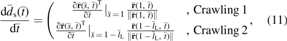
The displacement and duration time of the FifoBots in the crawling movements. Crawling 1 of the SH-FifoBot (a) with different length ratios and density ratios of hinge to limb and (b) with different length ratios of hinge to limb and stiffening ratios of hinge. (c) Crawling 1 and (d) Crawling 2 of the DH-FifoBot with different length ratios and density ratios of hinge to limb. (e) The crawling displacement with different coefficient ratios of kinematic to static friction. (f) A simplified sketch of the mapping from the robot's parameters to the movement performances of Crawling 1. The multiple meshes in (a)–(c) are differentiated by the friction ratio \documentclass{aastex}\usepackage{amsbsy}\usepackage{amsfonts}\usepackage{amssymb}\usepackage{bm}\usepackage{mathrsfs}\usepackage{pifont}\usepackage{stmaryrd}\usepackage{textcomp}\usepackage{portland, xspace}\usepackage{amsmath, amsxtra}\usepackage{upgreek}\pagestyle{empty}\DeclareMathSizes{10}{9}{7}{6}\begin{document}
$${ \mu _{{ \rm{Lk}}}} / { \mu _{{ \rm{Ls}}}}$$
\end{document}. Color images are available online.
The multiple meshes in the same plot are differentiated by \documentclass{aastex}\usepackage{amsbsy}\usepackage{amsfonts}\usepackage{amssymb}\usepackage{bm}\usepackage{mathrsfs}\usepackage{pifont}\usepackage{stmaryrd}\usepackage{textcomp}\usepackage{portland, xspace}\usepackage{amsmath, amsxtra}\usepackage{upgreek}\pagestyle{empty}\DeclareMathSizes{10}{9}{7}{6}\begin{document}
$${ \mu _{{ \rm{Lk}}}} / { \mu _{{ \rm{Ls}}}}$$
\end{document}. The alignment of different meshes along the vertical axis indicates that the friction ratio \documentclass{aastex}\usepackage{amsbsy}\usepackage{amsfonts}\usepackage{amssymb}\usepackage{bm}\usepackage{mathrsfs}\usepackage{pifont}\usepackage{stmaryrd}\usepackage{textcomp}\usepackage{portland, xspace}\usepackage{amsmath, amsxtra}\usepackage{upgreek}\pagestyle{empty}\DeclareMathSizes{10}{9}{7}{6}\begin{document}
$${ \mu _{{ \rm{Lk}}}} / { \mu _{{ \rm{Ls}}}}$$
\end{document} has no influence on the crawling time \documentclass{aastex}\usepackage{amsbsy}\usepackage{amsfonts}\usepackage{amssymb}\usepackage{bm}\usepackage{mathrsfs}\usepackage{pifont}\usepackage{stmaryrd}\usepackage{textcomp}\usepackage{portland, xspace}\usepackage{amsmath, amsxtra}\usepackage{upgreek}\pagestyle{empty}\DeclareMathSizes{10}{9}{7}{6}\begin{document}
$${ \bar t_{{ \rm{crawl}}}}$$
\end{document}, which only depends on the robot's deformation and the actuation speed. Larger \documentclass{aastex}\usepackage{amsbsy}\usepackage{amsfonts}\usepackage{amssymb}\usepackage{bm}\usepackage{mathrsfs}\usepackage{pifont}\usepackage{stmaryrd}\usepackage{textcomp}\usepackage{portland, xspace}\usepackage{amsmath, amsxtra}\usepackage{upgreek}\pagestyle{empty}\DeclareMathSizes{10}{9}{7}{6}\begin{document}
$${ \mu _{{ \rm{Lk}}}} / { \mu _{{ \rm{Ls}}}}$$
\end{document} (i.e., smaller difference between the static and kinematic frictional coefficients) allows the FifoBots to exhibit larger crawling displacement (Fig. 3a–c). Smaller \documentclass{aastex}\usepackage{amsbsy}\usepackage{amsfonts}\usepackage{amssymb}\usepackage{bm}\usepackage{mathrsfs}\usepackage{pifont}\usepackage{stmaryrd}\usepackage{textcomp}\usepackage{portland, xspace}\usepackage{amsmath, amsxtra}\usepackage{upgreek}\pagestyle{empty}\DeclareMathSizes{10}{9}{7}{6}\begin{document}
$${ \mu _{{ \rm{Lk}}}} / { \mu _{{ \rm{Ls}}}}$$
\end{document} indicates a lager required shifting distance of the mass center before effective crawling occurs as discussed above and thus reduces the crawling displacement measured at the rear support point. Figure 3 only shows the condition that the front contact point slides first because initial sliding of the rear contact point makes the crawling displacement always keep at the same level as that of \documentclass{aastex}\usepackage{amsbsy}\usepackage{amsfonts}\usepackage{amssymb}\usepackage{bm}\usepackage{mathrsfs}\usepackage{pifont}\usepackage{stmaryrd}\usepackage{textcomp}\usepackage{portland, xspace}\usepackage{amsmath, amsxtra}\usepackage{upgreek}\pagestyle{empty}\DeclareMathSizes{10}{9}{7}{6}\begin{document}
$${ \mu _{{ \rm{Lk}}}} / { \mu _{{ \rm{Ls}}}} = 1$$
\end{document} (Fig. 3e). Very small \documentclass{aastex}\usepackage{amsbsy}\usepackage{amsfonts}\usepackage{amssymb}\usepackage{bm}\usepackage{mathrsfs}\usepackage{pifont}\usepackage{stmaryrd}\usepackage{textcomp}\usepackage{portland, xspace}\usepackage{amsmath, amsxtra}\usepackage{upgreek}\pagestyle{empty}\DeclareMathSizes{10}{9}{7}{6}\begin{document}
$${ \mu _{{ \rm{Lk}}}} / { \mu _{{ \rm{Ls}}}}$$
\end{document} (less than 0.6 or 0.1 on the dashed curves in Fig. 3e) results in zero crawling displacement because the mass center never shifts to the required location for enabling the front contact point's sliding.
Comparing Figure 3a and b with c, the SH-FifoBot generally exhibits larger crawling displacement (with maximum value approximate to one) than the DH-FifoBot (with displacement below 0.7) in Crawling 1. The maximum displacement of Crawling 1 occurs with \documentclass{aastex}\usepackage{amsbsy}\usepackage{amsfonts}\usepackage{amssymb}\usepackage{bm}\usepackage{mathrsfs}\usepackage{pifont}\usepackage{stmaryrd}\usepackage{textcomp}\usepackage{portland, xspace}\usepackage{amsmath, amsxtra}\usepackage{upgreek}\pagestyle{empty}\DeclareMathSizes{10}{9}{7}{6}\begin{document}
$${ \mu _{{ \rm{Lk}}}} / { \mu _{{ \rm{Ls}}}} = 1$$
\end{document}, \documentclass{aastex}\usepackage{amsbsy}\usepackage{amsfonts}\usepackage{amssymb}\usepackage{bm}\usepackage{mathrsfs}\usepackage{pifont}\usepackage{stmaryrd}\usepackage{textcomp}\usepackage{portland, xspace}\usepackage{amsmath, amsxtra}\usepackage{upgreek}\pagestyle{empty}\DeclareMathSizes{10}{9}{7}{6}\begin{document}
$${ \bar l_{ \rm{H}}} / { \bar l_{ \rm{L}}} \approx 0$$
\end{document}, \documentclass{aastex}\usepackage{amsbsy}\usepackage{amsfonts}\usepackage{amssymb}\usepackage{bm}\usepackage{mathrsfs}\usepackage{pifont}\usepackage{stmaryrd}\usepackage{textcomp}\usepackage{portland, xspace}\usepackage{amsmath, amsxtra}\usepackage{upgreek}\pagestyle{empty}\DeclareMathSizes{10}{9}{7}{6}\begin{document}
$${ \bar \rho _{ \rm{H}}} / { \bar \rho _{ \rm{L}}} \approx 0$$
\end{document}, and \documentclass{aastex}\usepackage{amsbsy}\usepackage{amsfonts}\usepackage{amssymb}\usepackage{bm}\usepackage{mathrsfs}\usepackage{pifont}\usepackage{stmaryrd}\usepackage{textcomp}\usepackage{portland, xspace}\usepackage{amsmath, amsxtra}\usepackage{upgreek}\pagestyle{empty}\DeclareMathSizes{10}{9}{7}{6}\begin{document}
$${ \bar l_{{ \rm{Hs}}}} / { \bar l_{ \rm{H}}} \approx 0$$
\end{document}. The backward displacement produced in Crawling 2 (within −0.05 according to Fig. 3d) further reduces the crawling displacement of the DH-FifoBot.
For the Crawling 1 in Case 1 (corresponding to the major crescent-shaped patches of the meshes in Fig. 3a–c), as the length ratio \documentclass{aastex}\usepackage{amsbsy}\usepackage{amsfonts}\usepackage{amssymb}\usepackage{bm}\usepackage{mathrsfs}\usepackage{pifont}\usepackage{stmaryrd}\usepackage{textcomp}\usepackage{portland, xspace}\usepackage{amsmath, amsxtra}\usepackage{upgreek}\pagestyle{empty}\DeclareMathSizes{10}{9}{7}{6}\begin{document}
$${ \bar l_{ \rm{H}}} / { \bar l_{ \rm{L}}}$$
\end{document} increases, the crawling time first increases but then decreases while the crawling displacement always increases (at lower friction ratio \documentclass{aastex}\usepackage{amsbsy}\usepackage{amsfonts}\usepackage{amssymb}\usepackage{bm}\usepackage{mathrsfs}\usepackage{pifont}\usepackage{stmaryrd}\usepackage{textcomp}\usepackage{portland, xspace}\usepackage{amsmath, amsxtra}\usepackage{upgreek}\pagestyle{empty}\DeclareMathSizes{10}{9}{7}{6}\begin{document}
$${ \mu _{{ \rm{Lk}}}} / { \mu _{{ \rm{Ls}}}}$$
\end{document}) or decreases (at higher friction ratio \documentclass{aastex}\usepackage{amsbsy}\usepackage{amsfonts}\usepackage{amssymb}\usepackage{bm}\usepackage{mathrsfs}\usepackage{pifont}\usepackage{stmaryrd}\usepackage{textcomp}\usepackage{portland, xspace}\usepackage{amsmath, amsxtra}\usepackage{upgreek}\pagestyle{empty}\DeclareMathSizes{10}{9}{7}{6}\begin{document}
$${ \mu _{{ \rm{Lk}}}} / { \mu _{{ \rm{Ls}}}}$$
\end{document}). It is because that the crawling time is proportional to the total bending curvature and the bendable length of the flexible hinge [Eqs. (14) and (15)], that is, proportional to the hinge's bending angle, which is associated with the length ratio \documentclass{aastex}\usepackage{amsbsy}\usepackage{amsfonts}\usepackage{amssymb}\usepackage{bm}\usepackage{mathrsfs}\usepackage{pifont}\usepackage{stmaryrd}\usepackage{textcomp}\usepackage{portland, xspace}\usepackage{amsmath, amsxtra}\usepackage{upgreek}\pagestyle{empty}\DeclareMathSizes{10}{9}{7}{6}\begin{document}
$${ \bar l_{ \rm{H}}} / { \bar l_{ \rm{L}}}$$
\end{document} in a parabolic-like relationship. The crawling displacement (measured as the displacement of the rear end) occurs from the time when the mass center shifts forward by a distance, which increases with the friction ratio \documentclass{aastex}\usepackage{amsbsy}\usepackage{amsfonts}\usepackage{amssymb}\usepackage{bm}\usepackage{mathrsfs}\usepackage{pifont}\usepackage{stmaryrd}\usepackage{textcomp}\usepackage{portland, xspace}\usepackage{amsmath, amsxtra}\usepackage{upgreek}\pagestyle{empty}\DeclareMathSizes{10}{9}{7}{6}\begin{document}
$${ \mu _{{ \rm{Lk}}}} / { \mu _{{ \rm{Ls}}}}$$
\end{document} to the time when the mass center surmounts the front contact point. If the friction ratio is small, larger length ratio of hinge to limb (i.e., longer hinge) can improve the shifting displacement of the mass center to enable the rear end's sliding as soon as possible at the beginning of the crawling movement. With large friction ratio, shorter hinge (i.e., smaller \documentclass{aastex}\usepackage{amsbsy}\usepackage{amsfonts}\usepackage{amssymb}\usepackage{bm}\usepackage{mathrsfs}\usepackage{pifont}\usepackage{stmaryrd}\usepackage{textcomp}\usepackage{portland, xspace}\usepackage{amsmath, amsxtra}\usepackage{upgreek}\pagestyle{empty}\DeclareMathSizes{10}{9}{7}{6}\begin{document}
$${ \bar l_{ \rm{H}}} / { \bar l_{ \rm{L}}}$$
\end{document}) results in smaller final span distance between the rear and front contact points and thus increases the crawling displacement. The density ratio of hinge to limb and the stiffened length ratio of hinge affect the crawling movement in the same manner as the length ratio of hinge to limb, but their increase always leads to shorter crawling time.
The Case 2 of Crawling 1 (indicated by the minor triangular or trapezoid patches of the meshes in Fig. 3a–c) results from large \documentclass{aastex}\usepackage{amsbsy}\usepackage{amsfonts}\usepackage{amssymb}\usepackage{bm}\usepackage{mathrsfs}\usepackage{pifont}\usepackage{stmaryrd}\usepackage{textcomp}\usepackage{portland, xspace}\usepackage{amsmath, amsxtra}\usepackage{upgreek}\pagestyle{empty}\DeclareMathSizes{10}{9}{7}{6}\begin{document}
$${ \bar l_{ \rm{H}}} / { \bar l_{ \rm{L}}}$$
\end{document}, large \documentclass{aastex}\usepackage{amsbsy}\usepackage{amsfonts}\usepackage{amssymb}\usepackage{bm}\usepackage{mathrsfs}\usepackage{pifont}\usepackage{stmaryrd}\usepackage{textcomp}\usepackage{portland, xspace}\usepackage{amsmath, amsxtra}\usepackage{upgreek}\pagestyle{empty}\DeclareMathSizes{10}{9}{7}{6}\begin{document}
$${ \bar l_{{ \rm{Hs}}}} / { \bar l_{ \rm{H}}}$$
\end{document}, and small \documentclass{aastex}\usepackage{amsbsy}\usepackage{amsfonts}\usepackage{amssymb}\usepackage{bm}\usepackage{mathrsfs}\usepackage{pifont}\usepackage{stmaryrd}\usepackage{textcomp}\usepackage{portland, xspace}\usepackage{amsmath, amsxtra}\usepackage{upgreek}\pagestyle{empty}\DeclareMathSizes{10}{9}{7}{6}\begin{document}
$${ \bar \rho _{ \rm{H}}} / { \bar \rho _{ \rm{L}}}$$
\end{document}, with the extreme condition that the robot is totally composed of the flexible hinges without the limbs, that is, constituted by fully soft materials, but with the mass concentrated at the ends of each hinge. This case is avoided since it always lowers the crawling displacement and disables further movements of the SH-FifoBot, which is one of the reasons why the FifoBots are designed into the hybrid structure with both the flexible hinges and the rigid limbs. Increase of the density ratio (\documentclass{aastex}\usepackage{amsbsy}\usepackage{amsfonts}\usepackage{amssymb}\usepackage{bm}\usepackage{mathrsfs}\usepackage{pifont}\usepackage{stmaryrd}\usepackage{textcomp}\usepackage{portland, xspace}\usepackage{amsmath, amsxtra}\usepackage{upgreek}\pagestyle{empty}\DeclareMathSizes{10}{9}{7}{6}\begin{document}
$${ \bar \rho _{ \rm{H}}} / { \bar \rho _{ \rm{L}}}$$
\end{document}) induces increase (at low \documentclass{aastex}\usepackage{amsbsy}\usepackage{amsfonts}\usepackage{amssymb}\usepackage{bm}\usepackage{mathrsfs}\usepackage{pifont}\usepackage{stmaryrd}\usepackage{textcomp}\usepackage{portland, xspace}\usepackage{amsmath, amsxtra}\usepackage{upgreek}\pagestyle{empty}\DeclareMathSizes{10}{9}{7}{6}\begin{document}
$${ \mu _{{ \rm{Lk}}}} / { \mu _{{ \rm{Ls}}}}$$
\end{document}) or decrease (at high \documentclass{aastex}\usepackage{amsbsy}\usepackage{amsfonts}\usepackage{amssymb}\usepackage{bm}\usepackage{mathrsfs}\usepackage{pifont}\usepackage{stmaryrd}\usepackage{textcomp}\usepackage{portland, xspace}\usepackage{amsmath, amsxtra}\usepackage{upgreek}\pagestyle{empty}\DeclareMathSizes{10}{9}{7}{6}\begin{document}
$${ \mu _{{ \rm{Lk}}}} / { \mu _{{ \rm{Ls}}}}$$
\end{document}) of the crawling displacement but has no influence on the crawling time, observed from the vertical dashed lines in the minor triangular or trapezoid patches of the meshes shown in Figure 3a–c. Increasing \documentclass{aastex}\usepackage{amsbsy}\usepackage{amsfonts}\usepackage{amssymb}\usepackage{bm}\usepackage{mathrsfs}\usepackage{pifont}\usepackage{stmaryrd}\usepackage{textcomp}\usepackage{portland, xspace}\usepackage{amsmath, amsxtra}\usepackage{upgreek}\pagestyle{empty}\DeclareMathSizes{10}{9}{7}{6}\begin{document}
$${ \bar l_{ \rm{H}}} / { \bar l_{ \rm{L}}}$$
\end{document} or decreasing \documentclass{aastex}\usepackage{amsbsy}\usepackage{amsfonts}\usepackage{amssymb}\usepackage{bm}\usepackage{mathrsfs}\usepackage{pifont}\usepackage{stmaryrd}\usepackage{textcomp}\usepackage{portland, xspace}\usepackage{amsmath, amsxtra}\usepackage{upgreek}\pagestyle{empty}\DeclareMathSizes{10}{9}{7}{6}\begin{document}
$${ \bar l_{{ \rm{Hs}}}} / { \bar l_{ \rm{H}}}$$
\end{document} always results in decrease of the crawling displacement and increase of the crawling time. Based on the two conclusions above, the mapping from the robot's parameters to the crawling performances can be simplified from the meshes in Figure 3a–c into the sketch in Figure 3f.
According to Figure 3f, the crawling speed (i.e., \documentclass{aastex}\usepackage{amsbsy}\usepackage{amsfonts}\usepackage{amssymb}\usepackage{bm}\usepackage{mathrsfs}\usepackage{pifont}\usepackage{stmaryrd}\usepackage{textcomp}\usepackage{portland, xspace}\usepackage{amsmath, amsxtra}\usepackage{upgreek}\pagestyle{empty}\DeclareMathSizes{10}{9}{7}{6}\begin{document}
$${ \bar S_{{ \rm{crawl}}}} / { \bar t_{{ \rm{crawl}}}}$$
\end{document}) is optimal (at A1 and A2) when \documentclass{aastex}\usepackage{amsbsy}\usepackage{amsfonts}\usepackage{amssymb}\usepackage{bm}\usepackage{mathrsfs}\usepackage{pifont}\usepackage{stmaryrd}\usepackage{textcomp}\usepackage{portland, xspace}\usepackage{amsmath, amsxtra}\usepackage{upgreek}\pagestyle{empty}\DeclareMathSizes{10}{9}{7}{6}\begin{document}
$${ \bar l_{ \rm{H}}} / { \bar l_{ \rm{L}}}$$
\end{document} takes a medium value (in \documentclass{aastex}\usepackage{amsbsy}\usepackage{amsfonts}\usepackage{amssymb}\usepackage{bm}\usepackage{mathrsfs}\usepackage{pifont}\usepackage{stmaryrd}\usepackage{textcomp}\usepackage{portland, xspace}\usepackage{amsmath, amsxtra}\usepackage{upgreek}\pagestyle{empty}\DeclareMathSizes{10}{9}{7}{6}\begin{document}
$$0.25 \sim 1$$
\end{document} implied by Fig. 3a–c), \documentclass{aastex}\usepackage{amsbsy}\usepackage{amsfonts}\usepackage{amssymb}\usepackage{bm}\usepackage{mathrsfs}\usepackage{pifont}\usepackage{stmaryrd}\usepackage{textcomp}\usepackage{portland, xspace}\usepackage{amsmath, amsxtra}\usepackage{upgreek}\pagestyle{empty}\DeclareMathSizes{10}{9}{7}{6}\begin{document}
$${ \bar \rho _{ \rm{H}}} / { \bar \rho _{ \rm{L}}}$$
\end{document} and \documentclass{aastex}\usepackage{amsbsy}\usepackage{amsfonts}\usepackage{amssymb}\usepackage{bm}\usepackage{mathrsfs}\usepackage{pifont}\usepackage{stmaryrd}\usepackage{textcomp}\usepackage{portland, xspace}\usepackage{amsmath, amsxtra}\usepackage{upgreek}\pagestyle{empty}\DeclareMathSizes{10}{9}{7}{6}\begin{document}
$${ \bar l_{{ \rm{Hs}}}} / { \bar l_{ \rm{H}}}$$
\end{document} take the values as large as possible with an extreme condition that the robot mass only distributes on the hinges, and the SH-FifoBot's hinge is totally stiffened. In practice, the 3D printed rigid limbs take the major portion of the robot mass since they have larger density and numbers than the flexible hinges, which are hollow and made of lighter fabrics and elastomers. In addition, the SH-FifoBot's hinge should not be totally stiffened because a bendable length should be left to enable the folding deformation. Therefore, the crawling speed of the actual prototype is always below the optimal speed.
The backward crawling displacement of the DH-FifoBots in Crawling 2 is much smaller than the forward one in Crawling 1 (comparing Fig. 3d with c). The crawling time (\documentclass{aastex}\usepackage{amsbsy}\usepackage{amsfonts}\usepackage{amssymb}\usepackage{bm}\usepackage{mathrsfs}\usepackage{pifont}\usepackage{stmaryrd}\usepackage{textcomp}\usepackage{portland, xspace}\usepackage{amsmath, amsxtra}\usepackage{upgreek}\pagestyle{empty}\DeclareMathSizes{10}{9}{7}{6}\begin{document}
$${ \bar t_{{ \rm{crawl}}}}$$
\end{document}) only depends on the length ratio of hinge to limb (\documentclass{aastex}\usepackage{amsbsy}\usepackage{amsfonts}\usepackage{amssymb}\usepackage{bm}\usepackage{mathrsfs}\usepackage{pifont}\usepackage{stmaryrd}\usepackage{textcomp}\usepackage{portland, xspace}\usepackage{amsmath, amsxtra}\usepackage{upgreek}\pagestyle{empty}\DeclareMathSizes{10}{9}{7}{6}\begin{document}
$${ \bar l_{ \rm{H}}} / { \bar l_{ \rm{L}}}$$
\end{document}), whereas the crawling displacement is mainly determined by the density ratio (\documentclass{aastex}\usepackage{amsbsy}\usepackage{amsfonts}\usepackage{amssymb}\usepackage{bm}\usepackage{mathrsfs}\usepackage{pifont}\usepackage{stmaryrd}\usepackage{textcomp}\usepackage{portland, xspace}\usepackage{amsmath, amsxtra}\usepackage{upgreek}\pagestyle{empty}\DeclareMathSizes{10}{9}{7}{6}\begin{document}
$${ \bar \rho _{ \rm{H}}} / { \bar \rho _{ \rm{L}}}$$
\end{document}). To reduce the backward crawling displacement and time for improving the movement efficiency, the DH-FifoBot should be designed with smaller \documentclass{aastex}\usepackage{amsbsy}\usepackage{amsfonts}\usepackage{amssymb}\usepackage{bm}\usepackage{mathrsfs}\usepackage{pifont}\usepackage{stmaryrd}\usepackage{textcomp}\usepackage{portland, xspace}\usepackage{amsmath, amsxtra}\usepackage{upgreek}\pagestyle{empty}\DeclareMathSizes{10}{9}{7}{6}\begin{document}
$${ \bar l_{ \rm{H}}} / { \bar l_{ \rm{L}}}$$
\end{document} and larger \documentclass{aastex}\usepackage{amsbsy}\usepackage{amsfonts}\usepackage{amssymb}\usepackage{bm}\usepackage{mathrsfs}\usepackage{pifont}\usepackage{stmaryrd}\usepackage{textcomp}\usepackage{portland, xspace}\usepackage{amsmath, amsxtra}\usepackage{upgreek}\pagestyle{empty}\DeclareMathSizes{10}{9}{7}{6}\begin{document}
$${ \bar \rho _{ \rm{H}}} / { \bar \rho _{ \rm{L}}}$$
\end{document}, that is, with more mass distributed on the shorter hinges.
The folding displacement depicted in Figure 1 is determined by Equation (25). The folding displacement of the FifoBots depends on the robot's geometry parameters (i.e., \documentclass{aastex}\usepackage{amsbsy}\usepackage{amsfonts}\usepackage{amssymb}\usepackage{bm}\usepackage{mathrsfs}\usepackage{pifont}\usepackage{stmaryrd}\usepackage{textcomp}\usepackage{portland, xspace}\usepackage{amsmath, amsxtra}\usepackage{upgreek}\pagestyle{empty}\DeclareMathSizes{10}{9}{7}{6}\begin{document}
$${ \bar l_{ \rm{H}}} / { \bar l_{ \rm{L}}}$$
\end{document} and \documentclass{aastex}\usepackage{amsbsy}\usepackage{amsfonts}\usepackage{amssymb}\usepackage{bm}\usepackage{mathrsfs}\usepackage{pifont}\usepackage{stmaryrd}\usepackage{textcomp}\usepackage{portland, xspace}\usepackage{amsmath, amsxtra}\usepackage{upgreek}\pagestyle{empty}\DeclareMathSizes{10}{9}{7}{6}\begin{document}
$${ \bar l_{{ \rm{Hs}}}} / { \bar l_{ \rm{H}}}$$
\end{document}) and is not affected by the inertia parameter (\documentclass{aastex}\usepackage{amsbsy}\usepackage{amsfonts}\usepackage{amssymb}\usepackage{bm}\usepackage{mathrsfs}\usepackage{pifont}\usepackage{stmaryrd}\usepackage{textcomp}\usepackage{portland, xspace}\usepackage{amsmath, amsxtra}\usepackage{upgreek}\pagestyle{empty}\DeclareMathSizes{10}{9}{7}{6}\begin{document}
$${ \bar \rho _{ \rm{H}}} / { \bar \rho _{ \rm{L}}}$$
\end{document}) and the friction parameter (\documentclass{aastex}\usepackage{amsbsy}\usepackage{amsfonts}\usepackage{amssymb}\usepackage{bm}\usepackage{mathrsfs}\usepackage{pifont}\usepackage{stmaryrd}\usepackage{textcomp}\usepackage{portland, xspace}\usepackage{amsmath, amsxtra}\usepackage{upgreek}\pagestyle{empty}\DeclareMathSizes{10}{9}{7}{6}\begin{document}
$${ \mu _{{ \rm{Lk}}}} / { \mu _{{ \rm{Ls}}}}$$
\end{document}). Figure 4a indicates that the folding displacement of the SH-FifoBot increases as \documentclass{aastex}\usepackage{amsbsy}\usepackage{amsfonts}\usepackage{amssymb}\usepackage{bm}\usepackage{mathrsfs}\usepackage{pifont}\usepackage{stmaryrd}\usepackage{textcomp}\usepackage{portland, xspace}\usepackage{amsmath, amsxtra}\usepackage{upgreek}\pagestyle{empty}\DeclareMathSizes{10}{9}{7}{6}\begin{document}
$${ \bar l_{ \rm{H}}} / { \bar l_{ \rm{L}}}$$
\end{document} or \documentclass{aastex}\usepackage{amsbsy}\usepackage{amsfonts}\usepackage{amssymb}\usepackage{bm}\usepackage{mathrsfs}\usepackage{pifont}\usepackage{stmaryrd}\usepackage{textcomp}\usepackage{portland, xspace}\usepackage{amsmath, amsxtra}\usepackage{upgreek}\pagestyle{empty}\DeclareMathSizes{10}{9}{7}{6}\begin{document}
$${ \bar l_{{ \rm{Hs}}}} / { \bar l_{ \rm{H}}}$$
\end{document} increases. The two extreme conditions for \documentclass{aastex}\usepackage{amsbsy}\usepackage{amsfonts}\usepackage{amssymb}\usepackage{bm}\usepackage{mathrsfs}\usepackage{pifont}\usepackage{stmaryrd}\usepackage{textcomp}\usepackage{portland, xspace}\usepackage{amsmath, amsxtra}\usepackage{upgreek}\pagestyle{empty}\DeclareMathSizes{10}{9}{7}{6}\begin{document}
$${ \bar S_{{ \rm{fold}}}} = 0$$
\end{document} and \documentclass{aastex}\usepackage{amsbsy}\usepackage{amsfonts}\usepackage{amssymb}\usepackage{bm}\usepackage{mathrsfs}\usepackage{pifont}\usepackage{stmaryrd}\usepackage{textcomp}\usepackage{portland, xspace}\usepackage{amsmath, amsxtra}\usepackage{upgreek}\pagestyle{empty}\DeclareMathSizes{10}{9}{7}{6}\begin{document}
$${ \bar S_{{ \rm{fold}}}} = 1$$
\end{document} occur when \documentclass{aastex}\usepackage{amsbsy}\usepackage{amsfonts}\usepackage{amssymb}\usepackage{bm}\usepackage{mathrsfs}\usepackage{pifont}\usepackage{stmaryrd}\usepackage{textcomp}\usepackage{portland, xspace}\usepackage{amsmath, amsxtra}\usepackage{upgreek}\pagestyle{empty}\DeclareMathSizes{10}{9}{7}{6}\begin{document}
$${ \bar l_{{ \rm{Hs}}}} / { \bar l_{ \rm{H}}} = 0$$
\end{document}, \documentclass{aastex}\usepackage{amsbsy}\usepackage{amsfonts}\usepackage{amssymb}\usepackage{bm}\usepackage{mathrsfs}\usepackage{pifont}\usepackage{stmaryrd}\usepackage{textcomp}\usepackage{portland, xspace}\usepackage{amsmath, amsxtra}\usepackage{upgreek}\pagestyle{empty}\DeclareMathSizes{10}{9}{7}{6}\begin{document}
$${ \bar l_{{ \rm{Hs}}}} / { \bar l_{ \rm{H}}} = 0$$
\end{document} (i.e., the hinge shrinking into a point results in zero folding displacement due to the symmetrical rotation of its two limbs around the hinge point) and when \documentclass{aastex}\usepackage{amsbsy}\usepackage{amsfonts}\usepackage{amssymb}\usepackage{bm}\usepackage{mathrsfs}\usepackage{pifont}\usepackage{stmaryrd}\usepackage{textcomp}\usepackage{portland, xspace}\usepackage{amsmath, amsxtra}\usepackage{upgreek}\pagestyle{empty}\DeclareMathSizes{10}{9}{7}{6}\begin{document}
$${ \bar l_{{ \rm{Hs}}}} / { \bar l_{ \rm{H}}} = \infty$$
\end{document}, \documentclass{aastex}\usepackage{amsbsy}\usepackage{amsfonts}\usepackage{amssymb}\usepackage{bm}\usepackage{mathrsfs}\usepackage{pifont}\usepackage{stmaryrd}\usepackage{textcomp}\usepackage{portland, xspace}\usepackage{amsmath, amsxtra}\usepackage{upgreek}\pagestyle{empty}\DeclareMathSizes{10}{9}{7}{6}\begin{document}
$${ \bar l_{{ \rm{Hs}}}} / { \bar l_{ \rm{H}}} = 1$$
\end{document} (i.e., the robot totally constituted of the flexible stiffened hinge without rigid limbs exhibits a folding displacement equal to the robot's length), respectively. Despite the largest displacement, the second extreme condition is not allowed because it belongs to the Case 2 (Fig. 2a), which disables further movement of the SH-FifoBot. The Case 1 is confined below the black solid curve in Figure 4a with a maximum folding displacement of 0.5 (i.e., half length of the robot). The DH-FifoBot with \documentclass{aastex}\usepackage{amsbsy}\usepackage{amsfonts}\usepackage{amssymb}\usepackage{bm}\usepackage{mathrsfs}\usepackage{pifont}\usepackage{stmaryrd}\usepackage{textcomp}\usepackage{portland, xspace}\usepackage{amsmath, amsxtra}\usepackage{upgreek}\pagestyle{empty}\DeclareMathSizes{10}{9}{7}{6}\begin{document}
$${ \bar l_{{ \rm{Hs}}}} / { \bar l_{ \rm{H}}} = 0 \;{ \rm{and}} \; \infty$$
\end{document} results in the folding displacement of 0.66 and 0.51 (about 2/3 and 1/2 of the robot's total length), respectively, both allowing further movement of the robot. Without constraint on the geometry parameters (i.e., \documentclass{aastex}\usepackage{amsbsy}\usepackage{amsfonts}\usepackage{amssymb}\usepackage{bm}\usepackage{mathrsfs}\usepackage{pifont}\usepackage{stmaryrd}\usepackage{textcomp}\usepackage{portland, xspace}\usepackage{amsmath, amsxtra}\usepackage{upgreek}\pagestyle{empty}\DeclareMathSizes{10}{9}{7}{6}\begin{document}
$${ \bar l_{ \rm{H}}} / { \bar l_{ \rm{L}}}$$
\end{document}), the DH-FifoBot is more robust and easier to design than the SH-FifoBot. Larger folding displacement of the DH-FifoBot compensates its smaller crawling displacement when compared with the SH-FifoBot.
The displacement induced by the folding deformation of (a) the SH-FifoBot and (b) the DH-FifoBot. Color images are available online.
where \documentclass{aastex}\usepackage{amsbsy}\usepackage{amsfonts}\usepackage{amssymb}\usepackage{bm}\usepackage{mathrsfs}\usepackage{pifont}\usepackage{stmaryrd}\usepackage{textcomp}\usepackage{portland, xspace}\usepackage{amsmath, amsxtra}\usepackage{upgreek}\pagestyle{empty}\DeclareMathSizes{10}{9}{7}{6}\begin{document}
$${ \bar t_{{ \rm{crawl}}}}$$
\end{document} is the duration time of Crawling 1.
The falling movement
The falling movement follows Crawling 1 in Case 1 (Fig. 2a, b–), which is dominated by the inertia effect and would not be retarded by stopping the robot's deformation, that is, a dynamic process as mentioned above. Supposing the deformed shape (Fig. 2a, b) is maintained throughout the falling movement due to the deformation rate much slower than the dynamic movement speed, the FifoBots are modeled as a rigid bar falling from the upright (i.e., \documentclass{aastex}\usepackage{amsbsy}\usepackage{amsfonts}\usepackage{amssymb}\usepackage{bm}\usepackage{mathrsfs}\usepackage{pifont}\usepackage{stmaryrd}\usepackage{textcomp}\usepackage{portland, xspace}\usepackage{amsmath, amsxtra}\usepackage{upgreek}\pagestyle{empty}\DeclareMathSizes{10}{9}{7}{6}\begin{document}
$$\varphi = 0$$
\end{document}) to the inclined (i.e., \documentclass{aastex}\usepackage{amsbsy}\usepackage{amsfonts}\usepackage{amssymb}\usepackage{bm}\usepackage{mathrsfs}\usepackage{pifont}\usepackage{stmaryrd}\usepackage{textcomp}\usepackage{portland, xspace}\usepackage{amsmath, amsxtra}\usepackage{upgreek}\pagestyle{empty}\DeclareMathSizes{10}{9}{7}{6}\begin{document}
$$\varphi = { \varphi _1}$$
\end{document}) poses. The falling movement contains two processes: (1) at the beginning, the front end keeps pinned on the ground due to the static frictional force and the robot performs a pure rotation; (2) when the tangential reaction force at the pinned point exceeds the frictional force, the front end slides and the robot performs rotation as well as translation. Since the sliding displacement in the second process is very small (less than 4 mm or 1.3% of the robot's total length in experiment), we consider the robot to be pivoted at the front end on the ground, performing the falling movement like an inverted pendulum.
The initial height of the mass center (\documentclass{aastex}\usepackage{amsbsy}\usepackage{amsfonts}\usepackage{amssymb}\usepackage{bm}\usepackage{mathrsfs}\usepackage{pifont}\usepackage{stmaryrd}\usepackage{textcomp}\usepackage{portland, xspace}\usepackage{amsmath, amsxtra}\usepackage{upgreek}\pagestyle{empty}\DeclareMathSizes{10}{9}{7}{6}\begin{document}
$${ \bar h_{ \rm{c}}}$$
\end{document}) and the final inclined angle of the robot (\documentclass{aastex}\usepackage{amsbsy}\usepackage{amsfonts}\usepackage{amssymb}\usepackage{bm}\usepackage{mathrsfs}\usepackage{pifont}\usepackage{stmaryrd}\usepackage{textcomp}\usepackage{portland, xspace}\usepackage{amsmath, amsxtra}\usepackage{upgreek}\pagestyle{empty}\DeclareMathSizes{10}{9}{7}{6}\begin{document}
$${ \varphi _1}$$
\end{document}) in the falling movement indicated in Figure 2a and b and are obtained by Equations (26) and (27), respectively. From the equation of the falling dynamics [Eq. (28)], the angular velocity is resolved [Eq. (29)], and the falling time is further obtained [Eq. (30)] with the initial condition [Eq. (31)], in which all variables are in the nondimensional form. According to Equations (3)–(31), the falling time is calculated with different \documentclass{aastex}\usepackage{amsbsy}\usepackage{amsfonts}\usepackage{amssymb}\usepackage{bm}\usepackage{mathrsfs}\usepackage{pifont}\usepackage{stmaryrd}\usepackage{textcomp}\usepackage{portland, xspace}\usepackage{amsmath, amsxtra}\usepackage{upgreek}\pagestyle{empty}\DeclareMathSizes{10}{9}{7}{6}\begin{document}
$${ \bar l_{ \rm{H}}} / { \bar l_{ \rm{L}}}$$
\end{document} and \documentclass{aastex}\usepackage{amsbsy}\usepackage{amsfonts}\usepackage{amssymb}\usepackage{bm}\usepackage{mathrsfs}\usepackage{pifont}\usepackage{stmaryrd}\usepackage{textcomp}\usepackage{portland, xspace}\usepackage{amsmath, amsxtra}\usepackage{upgreek}\pagestyle{empty}\DeclareMathSizes{10}{9}{7}{6}\begin{document}
$${ \bar \rho _{ \rm{H}}} / { \bar \rho _{ \rm{L}}}$$
\end{document}, resulting in the contour plot in Figure 5.
The duration time in the falling movement of (a) the SH-FifoBot with different length and density ratios of hinge to limb, (b) the SH-FifoBot with different length ratios of hinge to limb and stiffening ratios of hinge, and (c) the DH-FifoBot with different length and density ratios of hinge to limb. Color images are available online.
where \documentclass{aastex}\usepackage{amsbsy}\usepackage{amsfonts}\usepackage{amssymb}\usepackage{bm}\usepackage{mathrsfs}\usepackage{pifont}\usepackage{stmaryrd}\usepackage{textcomp}\usepackage{portland, xspace}\usepackage{amsmath, amsxtra}\usepackage{upgreek}\pagestyle{empty}\DeclareMathSizes{10}{9}{7}{6}\begin{document}
$${ \varphi _0}$$
\end{document} and \documentclass{aastex}\usepackage{amsbsy}\usepackage{amsfonts}\usepackage{amssymb}\usepackage{bm}\usepackage{mathrsfs}\usepackage{pifont}\usepackage{stmaryrd}\usepackage{textcomp}\usepackage{portland, xspace}\usepackage{amsmath, amsxtra}\usepackage{upgreek}\pagestyle{empty}\DeclareMathSizes{10}{9}{7}{6}\begin{document}
$${ \bar \omega _0}$$
\end{document} are the initial angular position and velocity of robot in the falling movement. \documentclass{aastex}\usepackage{amsbsy}\usepackage{amsfonts}\usepackage{amssymb}\usepackage{bm}\usepackage{mathrsfs}\usepackage{pifont}\usepackage{stmaryrd}\usepackage{textcomp}\usepackage{portland, xspace}\usepackage{amsmath, amsxtra}\usepackage{upgreek}\pagestyle{empty}\DeclareMathSizes{10}{9}{7}{6}\begin{document}
$${ \rm{ang ( ) }}$$
\end{document} is a function returning the argument of a vector in the \documentclass{aastex}\usepackage{amsbsy}\usepackage{amsfonts}\usepackage{amssymb}\usepackage{bm}\usepackage{mathrsfs}\usepackage{pifont}\usepackage{stmaryrd}\usepackage{textcomp}\usepackage{portland, xspace}\usepackage{amsmath, amsxtra}\usepackage{upgreek}\pagestyle{empty}\DeclareMathSizes{10}{9}{7}{6}\begin{document}
$${ \mathbb{R}^2}$$
\end{document} space. \documentclass{aastex}\usepackage{amsbsy}\usepackage{amsfonts}\usepackage{amssymb}\usepackage{bm}\usepackage{mathrsfs}\usepackage{pifont}\usepackage{stmaryrd}\usepackage{textcomp}\usepackage{portland, xspace}\usepackage{amsmath, amsxtra}\usepackage{upgreek}\pagestyle{empty}\DeclareMathSizes{10}{9}{7}{6}\begin{document}
$${C_{{ \rm{plx}}}} ( )$$
\end{document} is a function converting an \documentclass{aastex}\usepackage{amsbsy}\usepackage{amsfonts}\usepackage{amssymb}\usepackage{bm}\usepackage{mathrsfs}\usepackage{pifont}\usepackage{stmaryrd}\usepackage{textcomp}\usepackage{portland, xspace}\usepackage{amsmath, amsxtra}\usepackage{upgreek}\pagestyle{empty}\DeclareMathSizes{10}{9}{7}{6}\begin{document}
$${ \mathbb{R}^2}$$
\end{document} vector into a complex number. j is the imaginary unit.
In Figure 5, the falling time makes sense only in Case 1 (i.e., the left patches of the parameter domain partitioned by the black solid curve). The falling time generally increases with the density ratio \documentclass{aastex}\usepackage{amsbsy}\usepackage{amsfonts}\usepackage{amssymb}\usepackage{bm}\usepackage{mathrsfs}\usepackage{pifont}\usepackage{stmaryrd}\usepackage{textcomp}\usepackage{portland, xspace}\usepackage{amsmath, amsxtra}\usepackage{upgreek}\pagestyle{empty}\DeclareMathSizes{10}{9}{7}{6}\begin{document}
$${ \bar \rho _{ \rm{H}}} / { \bar \rho _{ \rm{L}}}$$
\end{document} (Fig. 5a–c), explained by the larger gyration radius of the robot due to more of its mass distributed on the hinges, which are more distal from the pivot point than the limbs. As the length ratio \documentclass{aastex}\usepackage{amsbsy}\usepackage{amsfonts}\usepackage{amssymb}\usepackage{bm}\usepackage{mathrsfs}\usepackage{pifont}\usepackage{stmaryrd}\usepackage{textcomp}\usepackage{portland, xspace}\usepackage{amsmath, amsxtra}\usepackage{upgreek}\pagestyle{empty}\DeclareMathSizes{10}{9}{7}{6}\begin{document}
$${ \bar l_{ \rm{H}}} / { \bar l_{ \rm{L}}}$$
\end{document} increases, the falling time first increases but then decreases due to the larger gyration radius of rotation (resulting in longer falling time) as well as the smaller rotation angle (resulting in shorter falling time). For minimizing the falling time, \documentclass{aastex}\usepackage{amsbsy}\usepackage{amsfonts}\usepackage{amssymb}\usepackage{bm}\usepackage{mathrsfs}\usepackage{pifont}\usepackage{stmaryrd}\usepackage{textcomp}\usepackage{portland, xspace}\usepackage{amsmath, amsxtra}\usepackage{upgreek}\pagestyle{empty}\DeclareMathSizes{10}{9}{7}{6}\begin{document}
$${ \bar l_{ \rm{H}}} / { \bar l_{ \rm{L}}}$$
\end{document} should be designed as small or large as possible (i.e., enlarging the length difference between the limb and hinge) to decrease the gyration radius or reduce the rotation angle. The stiffened length ratio of the SH-FifoBot's hinge \documentclass{aastex}\usepackage{amsbsy}\usepackage{amsfonts}\usepackage{amssymb}\usepackage{bm}\usepackage{mathrsfs}\usepackage{pifont}\usepackage{stmaryrd}\usepackage{textcomp}\usepackage{portland, xspace}\usepackage{amsmath, amsxtra}\usepackage{upgreek}\pagestyle{empty}\DeclareMathSizes{10}{9}{7}{6}\begin{document}
$$( {{{{ \bar l}_{{ \rm{Hs}}}}} \mathord{ \left/ { \vphantom {{{{ \bar l}_{{ \rm{Hs}}}}} {{{ \bar l}_H}}}} \right. \kern- \nulldelimiterspace} {{{ \bar l}_H}}} )$$
\end{document} affects the falling time in the same manner as \documentclass{aastex}\usepackage{amsbsy}\usepackage{amsfonts}\usepackage{amssymb}\usepackage{bm}\usepackage{mathrsfs}\usepackage{pifont}\usepackage{stmaryrd}\usepackage{textcomp}\usepackage{portland, xspace}\usepackage{amsmath, amsxtra}\usepackage{upgreek}\pagestyle{empty}\DeclareMathSizes{10}{9}{7}{6}\begin{document}
$${{{{ \bar l}_{ \rm{H}}}} \mathord{ \left/ { \vphantom {{{{ \bar l}_{ \rm{H}}}} {{{ \bar l}_{ \rm{L}}}}}} \right. \kern- \nulldelimiterspace} {{{ \bar l}_{ \rm{L}}}}}$$
\end{document} (Fig. 5b).
Comparing Figure 5a and b with c, the DH-FifoBot exhibits shorter falling time than the SH-FifoBot because the gyration radius and rotation angle of the DH-FifoBot in the falling movement are smaller than that of the SH-FifoBot (compare Fig. 2a– with b–). In addition, the parameter domain indicates that the SH-FifoBot is more likely to perform the falling movement than the DH-FifoBot.
The rolling movement
The rolling movement of the FifoBots occurs in the developing phases. At the end of the crawling and falling movements (Figs. 2a or 6a for the SH-FifoBot, Figs. 2b or 6b for the DH-FifoBot), the robot is in a steady state with its mass center located above the lower limb (i.e., Limb 2 of the SH-FifoBot or Limb 3 of the DH-FifoBot) on which the robot's body reference xoy is set. As the active hinges stretches (Fig. 6a, b), the robot's mass center shifts forward until the mass center surmounts the right end point of the lower limb (a, b). Then, the robot rolls along the outer surface of the bended hinge (a, b) until another limb (i.e., Limb 1 of the SH-FifoBot or Limb 2 of the DH-FifoBot) lies on the ground (a, b), during which the robot's mass center is out of the sector formed by the bended hinge. For the SH-FifoBot, further developing of the hinge (a) allows the mass center to shift backward until it passes over the left end point of the horizontal limb on the ground (a) into the sector formed by the hinge (a), and then, the robot is fully developed to lie on the ground (a). For the DH-FifoBot, during the later rolling process (b–), the robot's mass center always locates above the middle limb between its two end point, allowing the robot to stall on the ground by the middle limb without backward rolling like the SH-FifoBot (a–).
The rolling movements of (a) the SH-FifoBot and (b) the DH-FifoBot during the developing phases.
The rolling movement described above is a succession of the static rolling (– and –) and the dynamic rolling ( and ). The static rolling movement requires the robot's mass center to locate above the limb that lies on the ground or within the sector formed by the bended hinge along which the robot rolls, while the dynamic rolling requires the mass center to locate out of the sector formed by the bended hinge. During the static rolling movement, the displacement and rotation angle of the robot are uniquely determined by the robot's deformation, and the movement can be blocked by stopping the deformation at any time, supposing the robot is actuated slowly. The dynamic rolling movement is mainly driven by the gravity and inertia, unable to be suspended by stopping the robot's deformation.
With different values of the parameters (i.e., \documentclass{aastex}\usepackage{amsbsy}\usepackage{amsfonts}\usepackage{amssymb}\usepackage{bm}\usepackage{mathrsfs}\usepackage{pifont}\usepackage{stmaryrd}\usepackage{textcomp}\usepackage{portland, xspace}\usepackage{amsmath, amsxtra}\usepackage{upgreek}\pagestyle{empty}\DeclareMathSizes{10}{9}{7}{6}\begin{document}
$${ \bar l_{ \rm{H}}} / { \bar l_{ \rm{L}}} , \;{ \bar \rho _{ \rm{H}}} / { \bar \rho _{ \rm{L}}}$$
\end{document}, and \documentclass{aastex}\usepackage{amsbsy}\usepackage{amsfonts}\usepackage{amssymb}\usepackage{bm}\usepackage{mathrsfs}\usepackage{pifont}\usepackage{stmaryrd}\usepackage{textcomp}\usepackage{portland, xspace}\usepackage{amsmath, amsxtra}\usepackage{upgreek}\pagestyle{empty}\DeclareMathSizes{10}{9}{7}{6}\begin{document}
$${ \bar l_{{ \rm{Hs}}}} / { \bar l_{ \rm{H}}}$$
\end{document} as discussed above), the rolling movement is unnecessary to be the same as that demonstrated in Figure 6, and multiple dynamic rolling processes may occur. To ensure all cases to be concerned, a general dynamic model for the rolling movement of the FifoBots is built based on the Lagrange equations. Supposing the straight limbs in Figure 6 are arcs with infinite radius, the robot always contacts with the ground by a convex surface, that is, via single contact point. Giving the arc length from the origin of the body reference to the contact point denoted as \documentclass{aastex}\usepackage{amsbsy}\usepackage{amsfonts}\usepackage{amssymb}\usepackage{bm}\usepackage{mathrsfs}\usepackage{pifont}\usepackage{stmaryrd}\usepackage{textcomp}\usepackage{portland, xspace}\usepackage{amsmath, amsxtra}\usepackage{upgreek}\pagestyle{empty}\DeclareMathSizes{10}{9}{7}{6}\begin{document}
$$\bar x ,$$
\end{document} the coordinate of any point on the robot in the body reference can be transformed into the coordinate in the fixed reference, that is, \documentclass{aastex}\usepackage{amsbsy}\usepackage{amsfonts}\usepackage{amssymb}\usepackage{bm}\usepackage{mathrsfs}\usepackage{pifont}\usepackage{stmaryrd}\usepackage{textcomp}\usepackage{portland, xspace}\usepackage{amsmath, amsxtra}\usepackage{upgreek}\pagestyle{empty}\DeclareMathSizes{10}{9}{7}{6}\begin{document}
$$^{ \rm{o}}{ \bar { \bf r}} ( \bar x , \bar s , \bar t )$$
\end{document} in Equation (32), supposing no sliding occurs during the rolling movement, and thus, \documentclass{aastex}\usepackage{amsbsy}\usepackage{amsfonts}\usepackage{amssymb}\usepackage{bm}\usepackage{mathrsfs}\usepackage{pifont}\usepackage{stmaryrd}\usepackage{textcomp}\usepackage{portland, xspace}\usepackage{amsmath, amsxtra}\usepackage{upgreek}\pagestyle{empty}\DeclareMathSizes{10}{9}{7}{6}\begin{document}
$$\bar x$$
\end{document} is also the coordinate of the contact point in the fixed reference. Here, the fixed reference is set to coincide with the body reference at the initial state shown in Figure 6a and b.
Taking \documentclass{aastex}\usepackage{amsbsy}\usepackage{amsfonts}\usepackage{amssymb}\usepackage{bm}\usepackage{mathrsfs}\usepackage{pifont}\usepackage{stmaryrd}\usepackage{textcomp}\usepackage{portland, xspace}\usepackage{amsmath, amsxtra}\usepackage{upgreek}\pagestyle{empty}\DeclareMathSizes{10}{9}{7}{6}\begin{document}
$$\bar x$$
\end{document} as the general coordinate, the dynamic and static Lagrange equations [Eqs. (36) and (37)] can be constructed through Equations (33)–(35), in which the first and second derivatives of \documentclass{aastex}\usepackage{amsbsy}\usepackage{amsfonts}\usepackage{amssymb}\usepackage{bm}\usepackage{mathrsfs}\usepackage{pifont}\usepackage{stmaryrd}\usepackage{textcomp}\usepackage{portland, xspace}\usepackage{amsmath, amsxtra}\usepackage{upgreek}\pagestyle{empty}\DeclareMathSizes{10}{9}{7}{6}\begin{document}
$$^{ \rm{o}}{ \bar{ \bf r}} ( \bar x , \bar s , \bar t )$$
\end{document} are listed in Appendix Equations (A10)–(A14). Rearranging the dynamic Lagrange equation yields the equation of the rolling dynamics [Eq. (38)], which is numerically solved with the explicit propagation method by setting the time and spatial interval as 0.001 in this research to obtain the rolling trajectory, that is, \documentclass{aastex}\usepackage{amsbsy}\usepackage{amsfonts}\usepackage{amssymb}\usepackage{bm}\usepackage{mathrsfs}\usepackage{pifont}\usepackage{stmaryrd}\usepackage{textcomp}\usepackage{portland, xspace}\usepackage{amsmath, amsxtra}\usepackage{upgreek}\pagestyle{empty}\DeclareMathSizes{10}{9}{7}{6}\begin{document}
$$\bar x ( \bar t )$$
\end{document}. The static Lagrange equation indicates that the stable equilibrium state of the robot occurs when the gravity potential is minimal, which is exploited to solve the robot's position (\documentclass{aastex}\usepackage{amsbsy}\usepackage{amsfonts}\usepackage{amssymb}\usepackage{bm}\usepackage{mathrsfs}\usepackage{pifont}\usepackage{stmaryrd}\usepackage{textcomp}\usepackage{portland, xspace}\usepackage{amsmath, amsxtra}\usepackage{upgreek}\pagestyle{empty}\DeclareMathSizes{10}{9}{7}{6}\begin{document}
$$\bar x$$
\end{document}) in the static rolling directly. The obtained \documentclass{aastex}\usepackage{amsbsy}\usepackage{amsfonts}\usepackage{amssymb}\usepackage{bm}\usepackage{mathrsfs}\usepackage{pifont}\usepackage{stmaryrd}\usepackage{textcomp}\usepackage{portland, xspace}\usepackage{amsmath, amsxtra}\usepackage{upgreek}\pagestyle{empty}\DeclareMathSizes{10}{9}{7}{6}\begin{document}
$$\bar x$$
\end{document} is then applied to calculate the rotation angle \documentclass{aastex}\usepackage{amsbsy}\usepackage{amsfonts}\usepackage{amssymb}\usepackage{bm}\usepackage{mathrsfs}\usepackage{pifont}\usepackage{stmaryrd}\usepackage{textcomp}\usepackage{portland, xspace}\usepackage{amsmath, amsxtra}\usepackage{upgreek}\pagestyle{empty}\DeclareMathSizes{10}{9}{7}{6}\begin{document}
$$\theta { \kern 1pt} ( \bar x , \bar t )$$
\end{document} expressed by Equation (5) or indicated in Figure 6a and b. The rolling trajectories \documentclass{aastex}\usepackage{amsbsy}\usepackage{amsfonts}\usepackage{amssymb}\usepackage{bm}\usepackage{mathrsfs}\usepackage{pifont}\usepackage{stmaryrd}\usepackage{textcomp}\usepackage{portland, xspace}\usepackage{amsmath, amsxtra}\usepackage{upgreek}\pagestyle{empty}\DeclareMathSizes{10}{9}{7}{6}\begin{document}
$$( \theta { \kern 1pt} ( \bar x , \bar t ) )$$
\end{document} of the FifoBots with different parameters and actuation speeds are presented in Figure 7.
The rotation angle of (a) the SH-FifoBot and (b) the DH-FifoBot, and the ratio of frictional to normal forces of (c) the SH-FifoBot and (d) the DH-FifoBot during the rolling movement. The upper and lower boundary of the nephogram of the potential energy is formed by the minimum rotation angle when the robot stalls on the proximal limb (relative to the origin of the body reference) and the maximum rotation angle when the robot stalls on the distal limb.
\documentclass{aastex}\usepackage{amsbsy}\usepackage{amsfonts}\usepackage{amssymb}\usepackage{bm}\usepackage{mathrsfs}\usepackage{pifont}\usepackage{stmaryrd}\usepackage{textcomp}\usepackage{portland, xspace}\usepackage{amsmath, amsxtra}\usepackage{upgreek}\pagestyle{empty}\DeclareMathSizes{10}{9}{7}{6}\begin{document}
\begin{align*}
^{ \rm{o}}{ \bar{ \bf r}} ( \bar x , \bar s , \bar t ) = { \bf{R}}{ [ \theta ( \bar x , \bar t ) ] ^T} [ { \bar{ \bf r}} ( \bar s , \bar t ) - { \bar{ \bf r}} ( \bar x , \bar t ) ] + {{ \bf{e}}_{ \rm{x}}} \bar x , \tag{32}
\end{align*}
\end{document}
\documentclass{aastex}\usepackage{amsbsy}\usepackage{amsfonts}\usepackage{amssymb}\usepackage{bm}\usepackage{mathrsfs}\usepackage{pifont}\usepackage{stmaryrd}\usepackage{textcomp}\usepackage{portland, xspace}\usepackage{amsmath, amsxtra}\usepackage{upgreek}\pagestyle{empty}\DeclareMathSizes{10}{9}{7}{6}\begin{document}
\begin{align*}
\bar V ( \bar x , \bar t ) = - { \bf{e}}_{ \rm{g}}^{ \rm{T}} \int_0^1 { \;^{ \rm{0}}}{ \bar{ \bf r}} ( \bar x , \bar s , \bar t ) \bar \rho ( \bar s ) { \rm{d}} \bar s , \tag{34}
\end{align*}
\end{document}\documentclass{aastex}\usepackage{amsbsy}\usepackage{amsfonts}\usepackage{amssymb}\usepackage{bm}\usepackage{mathrsfs}\usepackage{pifont}\usepackage{stmaryrd}\usepackage{textcomp}\usepackage{portland, xspace}\usepackage{amsmath, amsxtra}\usepackage{upgreek}\pagestyle{empty}\DeclareMathSizes{10}{9}{7}{6}\begin{document}
\begin{align*}
\bar L ( \bar \dot x , \bar x , \bar t ) = \bar T ( \bar \dot x , \bar x , \bar t ) - \bar V ( \bar x , \bar t ) , \tag{35}
\end{align*}
\end{document}\documentclass{aastex}\usepackage{amsbsy}\usepackage{amsfonts}\usepackage{amssymb}\usepackage{bm}\usepackage{mathrsfs}\usepackage{pifont}\usepackage{stmaryrd}\usepackage{textcomp}\usepackage{portland, xspace}\usepackage{amsmath, amsxtra}\usepackage{upgreek}\pagestyle{empty}\DeclareMathSizes{10}{9}{7}{6}\begin{document}
\begin{align*}
{ \rm { Dynamic: } } { \frac { \rm { d } } { { \rm { d } } \bar t } } \left( { { \frac { \partial \bar L } { \partial \bar \dot x } } } \right) - { \frac { \partial \bar L } { \partial \bar x } } = 0 , \tag { 36 }
\end{align*}
\end{document}\documentclass{aastex}\usepackage{amsbsy}\usepackage{amsfonts}\usepackage{amssymb}\usepackage{bm}\usepackage{mathrsfs}\usepackage{pifont}\usepackage{stmaryrd}\usepackage{textcomp}\usepackage{portland, xspace}\usepackage{amsmath, amsxtra}\usepackage{upgreek}\pagestyle{empty}\DeclareMathSizes{10}{9}{7}{6}\begin{document}
\begin{align*}
{ \rm { Static: } } { \frac { \partial \bar V } { \partial \bar x } } = 0 \; { \rm { and } } { \frac { { \partial ^2 } \bar V } { \partial { { \bar x } ^2 } } } < 0 , \tag { 37 }
\end{align*}
\end{document}
\documentclass{aastex}\usepackage{amsbsy}\usepackage{amsfonts}\usepackage{amssymb}\usepackage{bm}\usepackage{mathrsfs}\usepackage{pifont}\usepackage{stmaryrd}\usepackage{textcomp}\usepackage{portland, xspace}\usepackage{amsmath, amsxtra}\usepackage{upgreek}\pagestyle{empty}\DeclareMathSizes{10}{9}{7}{6}\begin{document}
\begin{align*}
{ \frac { \bar F } { \bar N } } = \tan \left\{ { { \rm { arg } } \left[ { \int_0^1 \left( { { \frac { { \partial ^2 } ^ { \rm { o } } { \bar { \bf r } } } { \partial { { \bar x } ^2 } } } { { \bar \dot x } ^2 } + 2 { \frac { { \partial ^2 } ^ { \rm { o } } { \bar { \bf r } } } { \partial \bar x \partial \bar t } } \bar \dot x + { \frac { { \partial ^2 } ^ { \rm { o } } { \bar { \bf r } } } { \partial { { \bar t } ^2 } } } - { { \bf { e } } _ { \rm { g } } } } \right) \bar \rho ( \bar s ) { \rm { d } } \bar s } \right] } \right\} . \tag { 39 }
\end{align*}
\end{document}
The rotation trajectories are plotted on the nephogram of the robot's gravity potential energy (Fig. 7) to demonstrate the motivation of the rolling movement. Tending to minimize the potential energy [Eq. (37)], the robot always transfers its state along the negative gradient of the potential energy with respect to the rotation angle. During the first static rolling process (Fig. 6a, b–), no rotation angle occurs, exhibiting the zero-level lines at the beginning of the rotation trajectories in Figure 7a and b, since any rotation in this process would increase the potential energy. The static process lasts as the robot develops until the mass center surmounts the front end of the horizontal limb (Fig. 6a, b), that is, the rotation trajectories in Figure 7a and b start to rise at the peak point of the potential energy (with respect to \documentclass{aastex}\usepackage{amsbsy}\usepackage{amsfonts}\usepackage{amssymb}\usepackage{bm}\usepackage{mathrsfs}\usepackage{pifont}\usepackage{stmaryrd}\usepackage{textcomp}\usepackage{portland, xspace}\usepackage{amsmath, amsxtra}\usepackage{upgreek}\pagestyle{empty}\DeclareMathSizes{10}{9}{7}{6}\begin{document}
$$\theta$$
\end{document}). After that, the robot performs the dynamic rotation (Fig. 6a, b–) to diminish the potential energy, that is, the trajectories in Figure 7 prolongates generally along the negative gradient of the potential energy with some deviation depending on the actuation speed. The dynamics rolling process lasts until the robot stalls on another limb (Fig. 6a, b), that is, the trajectories in Figure 7 reaches a maximum height at which the potential energy is of a valley value. After the dynamic rolling process, the robot returns to the static rolling again (Fig. 6a, b–) and continues to develops until it stretches fully, that is, the trajectories in Figure 7 descend to the zero level along a valley (for the DH-FifoBot) or the upper boundary (for the SH-FifoBot) of the potential energy's nephogram.
The actuation speed majorly affects the dynamic rolling movement by reducing the rotation angle and prolonging the dynamic rolling time, also shrinking the final static rolling time (Fig. 7). Higher actuation speed can inhibit the undulation of the rear limb (i.e., Limb 2 in Fig. 6a or Limb 3 in Fig. 6b). The parameters of the robot (\documentclass{aastex}\usepackage{amsbsy}\usepackage{amsfonts}\usepackage{amssymb}\usepackage{bm}\usepackage{mathrsfs}\usepackage{pifont}\usepackage{stmaryrd}\usepackage{textcomp}\usepackage{portland, xspace}\usepackage{amsmath, amsxtra}\usepackage{upgreek}\pagestyle{empty}\DeclareMathSizes{10}{9}{7}{6}\begin{document}
$${{{{ \bar l}_{ \rm{H}}}} \mathord{ \left/ { \vphantom {{{{ \bar l}_{ \rm{H}}}} {{{ \bar l}_{ \rm{L}}}}}} \right. \kern- \nulldelimiterspace} {{{ \bar l}_{ \rm{L}}}}}$$
\end{document} and \documentclass{aastex}\usepackage{amsbsy}\usepackage{amsfonts}\usepackage{amssymb}\usepackage{bm}\usepackage{mathrsfs}\usepackage{pifont}\usepackage{stmaryrd}\usepackage{textcomp}\usepackage{portland, xspace}\usepackage{amsmath, amsxtra}\usepackage{upgreek}\pagestyle{empty}\DeclareMathSizes{10}{9}{7}{6}\begin{document}
$${{{{ \bar \rho }_{ \rm{H}}}} \mathord{ \left/ { \vphantom {{{{ \bar \rho }_{ \rm{H}}}} {{{ \bar \rho }_{ \rm{L}}}}}} \right. \kern- \nulldelimiterspace} {{{ \bar \rho }_{ \rm{L}}}}}$$
\end{document}) influence the rolling movement by changing the nephogram of the potential energy. Longer hinge (i.e., larger \documentclass{aastex}\usepackage{amsbsy}\usepackage{amsfonts}\usepackage{amssymb}\usepackage{bm}\usepackage{mathrsfs}\usepackage{pifont}\usepackage{stmaryrd}\usepackage{textcomp}\usepackage{portland, xspace}\usepackage{amsmath, amsxtra}\usepackage{upgreek}\pagestyle{empty}\DeclareMathSizes{10}{9}{7}{6}\begin{document}
$${{{{ \bar l}_{ \rm{H}}}} \mathord{ \left/ { \vphantom {{{{ \bar l}_{ \rm{H}}}} {{{ \bar l}_{ \rm{L}}}}}} \right. \kern- \nulldelimiterspace} {{{ \bar l}_{ \rm{L}}}}}$$
\end{document}) causes the potential energy's nephogram to shift downward, resulting in expansion of the area for the dynamic rolling movement and larger rotation angle of the robot (comparing Fig. 7a and with a and ). It is because that the rounder profile exhibited by longer hinge in folding state enhances the rolling movement. The density ratio of hinge to limb \documentclass{aastex}\usepackage{amsbsy}\usepackage{amsfonts}\usepackage{amssymb}\usepackage{bm}\usepackage{mathrsfs}\usepackage{pifont}\usepackage{stmaryrd}\usepackage{textcomp}\usepackage{portland, xspace}\usepackage{amsmath, amsxtra}\usepackage{upgreek}\pagestyle{empty}\DeclareMathSizes{10}{9}{7}{6}\begin{document}
$${{{{ \bar \rho }_{ \rm{H}}}} \mathord{ \left/ { \vphantom {{{{ \bar \rho }_{ \rm{H}}}} {{{ \bar \rho }_{ \rm{L}}}}}} \right. \kern- \nulldelimiterspace} {{{ \bar \rho }_{ \rm{L}}}}}$$
\end{document} affects the rolling movement in the same manner as the length ratio \documentclass{aastex}\usepackage{amsbsy}\usepackage{amsfonts}\usepackage{amssymb}\usepackage{bm}\usepackage{mathrsfs}\usepackage{pifont}\usepackage{stmaryrd}\usepackage{textcomp}\usepackage{portland, xspace}\usepackage{amsmath, amsxtra}\usepackage{upgreek}\pagestyle{empty}\DeclareMathSizes{10}{9}{7}{6}\begin{document}
$${{{{ \bar l}_{ \rm{H}}}} \mathord{ \left/ { \vphantom {{{{ \bar l}_{ \rm{H}}}} {{{ \bar l}_{ \rm{L}}}}}} \right. \kern- \nulldelimiterspace} {{{ \bar l}_{ \rm{L}}}}}$$
\end{document} (comparing Fig. 7a, b and with a, b and ).
For the DH-FifoBot, too long hinge leads to a different behavior of the rolling movement (Fig. 7b and ), in which the trajectories surmount and pass over the potential barrier to reach the upper boundary of the nephogram during the dynamic rolling process, followed by a static and another dynamic rolling process. This process continues the rolling process as shown in Figure 6b– but is different from the process b–. Instead of stalling on the middle limb after the state of Figure 6b like the process b–, the robot continues to roll until it stalls on the third limb (i.e., Limb 1) and then performs a backward static and dynamic rolling movement as the robot further develops to the fully stretched state.
The ratio of the frictional to the normal forces [i.e., \documentclass{aastex}\usepackage{amsbsy}\usepackage{amsfonts}\usepackage{amssymb}\usepackage{bm}\usepackage{mathrsfs}\usepackage{pifont}\usepackage{stmaryrd}\usepackage{textcomp}\usepackage{portland, xspace}\usepackage{amsmath, amsxtra}\usepackage{upgreek}\pagestyle{empty}\DeclareMathSizes{10}{9}{7}{6}\begin{document}
$$\bar F{ \rm{ / }} \bar N$$
\end{document} in Eq. (39)] during the rolling movement is calculated and plotted (Fig. 7c, d). The \documentclass{aastex}\usepackage{amsbsy}\usepackage{amsfonts}\usepackage{amssymb}\usepackage{bm}\usepackage{mathrsfs}\usepackage{pifont}\usepackage{stmaryrd}\usepackage{textcomp}\usepackage{portland, xspace}\usepackage{amsmath, amsxtra}\usepackage{upgreek}\pagestyle{empty}\DeclareMathSizes{10}{9}{7}{6}\begin{document}
$$\bar F{ \rm{ / }} \bar N$$
\end{document} exceeding the contact frictional coefficient between the robot (limbs or hinges) and the ground would lead to sliding of the contact point and thus result in reduction of the displacement. Figure 7c and d and indicates that with shorter hinge (i.e., low \documentclass{aastex}\usepackage{amsbsy}\usepackage{amsfonts}\usepackage{amssymb}\usepackage{bm}\usepackage{mathrsfs}\usepackage{pifont}\usepackage{stmaryrd}\usepackage{textcomp}\usepackage{portland, xspace}\usepackage{amsmath, amsxtra}\usepackage{upgreek}\pagestyle{empty}\DeclareMathSizes{10}{9}{7}{6}\begin{document}
$${ \bar l_{ \rm{H}}}{ \rm{ / }}{ \bar l_{ \rm{L}}}$$
\end{document}), the frictional to normal force ratios \documentclass{aastex}\usepackage{amsbsy}\usepackage{amsfonts}\usepackage{amssymb}\usepackage{bm}\usepackage{mathrsfs}\usepackage{pifont}\usepackage{stmaryrd}\usepackage{textcomp}\usepackage{portland, xspace}\usepackage{amsmath, amsxtra}\usepackage{upgreek}\pagestyle{empty}\DeclareMathSizes{10}{9}{7}{6}\begin{document}
$$\bar F{ \rm{ / }} \bar N$$
\end{document} in the rolling movements of the SH-FifoBot and DH-FifoBot with different actuation speeds \documentclass{aastex}\usepackage{amsbsy}\usepackage{amsfonts}\usepackage{amssymb}\usepackage{bm}\usepackage{mathrsfs}\usepackage{pifont}\usepackage{stmaryrd}\usepackage{textcomp}\usepackage{portland, xspace}\usepackage{amsmath, amsxtra}\usepackage{upgreek}\pagestyle{empty}\DeclareMathSizes{10}{9}{7}{6}\begin{document}
$${ \rm{d}} \bar \kappa { \rm{ / d}} \bar t$$
\end{document} are consistent, although enlarged by smaller \documentclass{aastex}\usepackage{amsbsy}\usepackage{amsfonts}\usepackage{amssymb}\usepackage{bm}\usepackage{mathrsfs}\usepackage{pifont}\usepackage{stmaryrd}\usepackage{textcomp}\usepackage{portland, xspace}\usepackage{amsmath, amsxtra}\usepackage{upgreek}\pagestyle{empty}\DeclareMathSizes{10}{9}{7}{6}\begin{document}
$${ \bar \rho _{ \rm{H}}}{ \rm{ / }}{ \bar \rho _{ \rm{L}}}.$$
\end{document} The peak values of \documentclass{aastex}\usepackage{amsbsy}\usepackage{amsfonts}\usepackage{amssymb}\usepackage{bm}\usepackage{mathrsfs}\usepackage{pifont}\usepackage{stmaryrd}\usepackage{textcomp}\usepackage{portland, xspace}\usepackage{amsmath, amsxtra}\usepackage{upgreek}\pagestyle{empty}\DeclareMathSizes{10}{9}{7}{6}\begin{document}
$$\bar F{ \rm{ / }} \bar N$$
\end{document} always occur at the beginning of the rolling movement (Fig. 6a, b) and may induce a backlash sliding due to the inertia recoil during the robot's deformation. From Figure 7c and , it is observed that the peak point of \documentclass{aastex}\usepackage{amsbsy}\usepackage{amsfonts}\usepackage{amssymb}\usepackage{bm}\usepackage{mathrsfs}\usepackage{pifont}\usepackage{stmaryrd}\usepackage{textcomp}\usepackage{portland, xspace}\usepackage{amsmath, amsxtra}\usepackage{upgreek}\pagestyle{empty}\DeclareMathSizes{10}{9}{7}{6}\begin{document}
$$\bar F{ \rm{ / }} \bar N$$
\end{document} tends to be delayed by higher actuation speed if the robot's hinge is long (i.e., with high \documentclass{aastex}\usepackage{amsbsy}\usepackage{amsfonts}\usepackage{amssymb}\usepackage{bm}\usepackage{mathrsfs}\usepackage{pifont}\usepackage{stmaryrd}\usepackage{textcomp}\usepackage{portland, xspace}\usepackage{amsmath, amsxtra}\usepackage{upgreek}\pagestyle{empty}\DeclareMathSizes{10}{9}{7}{6}\begin{document}
$${ \bar l_{ \rm{H}}} / { \bar l_{ \rm{L}}}$$
\end{document}), which is mainly caused by the prolonged dynamic rolling process discussed above. Figure 7d shows that the DH-FifoBot with long hinges (i.e., high \documentclass{aastex}\usepackage{amsbsy}\usepackage{amsfonts}\usepackage{amssymb}\usepackage{bm}\usepackage{mathrsfs}\usepackage{pifont}\usepackage{stmaryrd}\usepackage{textcomp}\usepackage{portland, xspace}\usepackage{amsmath, amsxtra}\usepackage{upgreek}\pagestyle{empty}\DeclareMathSizes{10}{9}{7}{6}\begin{document}
$${ \bar l_{ \rm{H}}}{ \rm{ / }}{ \bar l_{ \rm{L}}}$$
\end{document}) exhibits large \documentclass{aastex}\usepackage{amsbsy}\usepackage{amsfonts}\usepackage{amssymb}\usepackage{bm}\usepackage{mathrsfs}\usepackage{pifont}\usepackage{stmaryrd}\usepackage{textcomp}\usepackage{portland, xspace}\usepackage{amsmath, amsxtra}\usepackage{upgreek}\pagestyle{empty}\DeclareMathSizes{10}{9}{7}{6}\begin{document}
$$\bar F{ \rm{ / }} \bar N$$
\end{document} and thus is more prone to sliding during the rolling movement than the SH-FifoBot.
Through the analysis above, the feasibility of the FifoBot for flipping locomotion is verified in theory. The following section is to explore the actual locomotion performances of the FifoBots by experiments.
Prototype
In this section, prototypes of the SH-FifoBot and DH-FifoBot are presented, including the linear and quadrilateral morphologies. Since the flexible hinges are made of bidirectional bending soft actuators, we introduce the soft actuators first and then illustrate structural constitution of the FifoBots.
The soft actuators
According previous researches, there are several types of soft bending actuators available, including the elastomer pneumatic actuators based on PneuNets,1 fiber reinforcement,63 or foam infill;64 the CPAMs;65 the cable-driven actuators;66 the shape memory alloy-driven actuators;67 and the electric actuators based on electroactive polymers.68 Considering that large range of motion and output force are needed, we choose the pneumatic actuators for the proposed robots. Among the pneumatic ones, the CPAMs are more suitable than the elastomer pneumatic actuators in constructing the bidirectional bendable hinges because its braided fabrics in unactuated state are highly flexible and produce no resistance to the actuated side. Therefore, in the prototypes, the CPAMs are applied in the bidirectional bendable hinges.
The CPAMs can perform bending by filling fabric-encircled bladder with pressurized air. They are based on conventional extensor PAMs that are reinforced at one side65 with an inextensible fiber or fabric layer, as shown in Figure 8a (top). This type of soft actuators have been commonly applied in soft robots and exoskeletons.69–71 By bundling up two identical CPAMs at their reinforced sides, a customized bidirectional bendable CPAM (middle) is obtained, which is used as the flexible hinges of the quadrilateral DH-FifoBot. By connecting several such bidirectional CPAMs in parallel, a parallel CPAM (bottom) is constructed, which can function as the flexible hinges of the linear DH-FifoBot.
Structure design of the FifoBots. (a) Soft actuators for hinges of the DH-FifoBots. (b) Soft actuators for hinges of the SH-FifoBots. (c) The linear SH-FifoBot and (d) the linear DH-FifoBot, and their quadrilateral morphologies in (e) and (f), respectively.
Different from the DH-FifoBots, the SH-FifoBots have their flexible hinges stiffness-patterned, as mentioned in the Locomotion Principle section. Previous researches have proposed several methods of patterning stiffness of soft actuators, such as covering with selectively placed sleeve,63 embedding unstretchable materials,72 and integrating jamming particle.73 Here, we use the first method, that is, partially covering the soft actuator with inextensible layer such as unstretchable fabrics, as shown in Figure 8b. On the upper side, the inextensible layer (cotton and linen fabric) covers proximal part of the soft actuator to make it stiffen during the downward bending (bottom). On the lower side, the layer covers the distal part and makes it stiffen during the upward bending (top). Therefore, the upward bending occurs at the proximal segment, whereas the downward bending occurs at the distal segment. They are nonsymmetric and have different hinge points (middle points of the arcs). Stiffness of the soft actuator shown in Figure 8a (bottom) can also be patterned in the same way. By using these soft actuators as the flexible hinges, the SH-FifoBots can achieve flipping locomotion as described above.
The FifoBots
Structures of the FifoBots in different morphologies are shown in Figure 8c–f. The flexible hinges are clamped at two ends by the rigid limbs. The hinges are made of the CPAMs mentioned above. The limbs are made of two 3D printed parts (upper and lower), which are assembled by screws. On the limbs that contain tube connectors, via the holes are designed for the pneumatic tubes. In the linear morphology, the hinges are made of the parallel CPAMs, and the limbs are designed into rectangular sheet shape. In the quadrilateral morphology, the hinges are made of the bidirectional CPAMs, and the limbs are designed into L or cross sheet shape. For the SH-FifoBots, their flexible hinges are stiffness-patterned by inextensible layers.
Dimensions and mass of the designed FifoBots are shown in Figure 8d and e and listed in Table 2. These parameters are mainly checked by two criteria. The first one is that the flexible hinge should be able to fold fully, that is, bending by 180°. At this state, the radius of bending curvature should be larger than \documentclass{aastex}\usepackage{amsbsy}\usepackage{amsfonts}\usepackage{amssymb}\usepackage{bm}\usepackage{mathrsfs}\usepackage{pifont}\usepackage{stmaryrd}\usepackage{textcomp}\usepackage{portland, xspace}\usepackage{amsmath, amsxtra}\usepackage{upgreek}\pagestyle{empty}\DeclareMathSizes{10}{9}{7}{6}\begin{document}
$$h{ \rm{ / }}2 ,$$
\end{document} which indicates that bending length of the flexible hinge should be larger than \documentclass{aastex}\usepackage{amsbsy}\usepackage{amsfonts}\usepackage{amssymb}\usepackage{bm}\usepackage{mathrsfs}\usepackage{pifont}\usepackage{stmaryrd}\usepackage{textcomp}\usepackage{portland, xspace}\usepackage{amsmath, amsxtra}\usepackage{upgreek}\pagestyle{empty}\DeclareMathSizes{10}{9}{7}{6}\begin{document}
$$\pi h{ \rm{ / }}2 ,$$
\end{document} that is, about 50 mm. The second one is that mass center of the robot should be on the right of the most left contact point at beginning of the developing phase (Fig. 1a, b). For the DH-FifoBots, this criterion is satisfied naturally since the parameter domain of Crawling 2 is not partitioned into two cases like Crawling 1 (comparing Fig. 3d with a, b). For the SH-FifoBots, the parameters should ensure the robot to work in Case 2 (Fig. 2a), which means that the parameters should fall within the parameter domain of Case 1 (Fig. 5a, b). From the parameters given in Table 2, the length and density ratio of hinge to limb and the stiffened length ratio of the SH-FifoBot's hinge are calculated and listed in Table 2, which indeed fall within the required parameter domain mentioned above.
In addition, the ratio of the kinematic to the static frictional coefficient is measured by the sliding experiment74 on a polyvinyl chloride sheet, which is also used as the ground for the flipping locomotion. The measured kinematic and static frictional coefficients are \documentclass{aastex}\usepackage{amsbsy}\usepackage{amsfonts}\usepackage{amssymb}\usepackage{bm}\usepackage{mathrsfs}\usepackage{pifont}\usepackage{stmaryrd}\usepackage{textcomp}\usepackage{portland, xspace}\usepackage{amsmath, amsxtra}\usepackage{upgreek}\pagestyle{empty}\DeclareMathSizes{10}{9}{7}{6}\begin{document}
$$0.12 \pm 0.02$$
\end{document} and \documentclass{aastex}\usepackage{amsbsy}\usepackage{amsfonts}\usepackage{amssymb}\usepackage{bm}\usepackage{mathrsfs}\usepackage{pifont}\usepackage{stmaryrd}\usepackage{textcomp}\usepackage{portland, xspace}\usepackage{amsmath, amsxtra}\usepackage{upgreek}\pagestyle{empty}\DeclareMathSizes{10}{9}{7}{6}\begin{document}
$$0.27 \pm 0.03$$
\end{document}, respectively, in which the kinematic friction is measured at the sliding velocity of 200 mm/s.74 The kinematic to static frictional coefficient ratio is therefore determined as \documentclass{aastex}\usepackage{amsbsy}\usepackage{amsfonts}\usepackage{amssymb}\usepackage{bm}\usepackage{mathrsfs}\usepackage{pifont}\usepackage{stmaryrd}\usepackage{textcomp}\usepackage{portland, xspace}\usepackage{amsmath, amsxtra}\usepackage{upgreek}\pagestyle{empty}\DeclareMathSizes{10}{9}{7}{6}\begin{document}
$${ \mu _{{ \rm{Lk}}}}{ \rm{ / }}{ \mu _{{ \rm{Ls}}}} = 0.44$$
\end{document}. Taking these parameters into the model built before, the displacement and duration time in each stage of the flipping locomotion can be calculated. It should be noted that the calculated results are dimensionless and should be scaled by the length unit l and the time unit \documentclass{aastex}\usepackage{amsbsy}\usepackage{amsfonts}\usepackage{amssymb}\usepackage{bm}\usepackage{mathrsfs}\usepackage{pifont}\usepackage{stmaryrd}\usepackage{textcomp}\usepackage{portland, xspace}\usepackage{amsmath, amsxtra}\usepackage{upgreek}\pagestyle{empty}\DeclareMathSizes{10}{9}{7}{6}\begin{document}
$$\sqrt {l / g}$$
\end{document} as we set before to obtain the dimensional or physical results. It can be predicted that the moving speed of the FifoBots is proportional to \documentclass{aastex}\usepackage{amsbsy}\usepackage{amsfonts}\usepackage{amssymb}\usepackage{bm}\usepackage{mathrsfs}\usepackage{pifont}\usepackage{stmaryrd}\usepackage{textcomp}\usepackage{portland, xspace}\usepackage{amsmath, amsxtra}\usepackage{upgreek}\pagestyle{empty}\DeclareMathSizes{10}{9}{7}{6}\begin{document}
$$\sqrt {gl} ,$$
\end{document} that is, the larger size, the higher speed.
Experiments
This section presents characterization of the flexible hinges and locomotion experiments of the FifoBots, including linear movement of the linear FifoBots and biaxial movements of the quadrilateral FifoBots.
Characterization of flexible hinges
Since flipping locomotion of the FifoBots relies on bending of the flexible hinges, it is necessary to explore their bending performances. From previous studies, most soft actuators are characterized by their free bending degree and tip force.69,75 Therefore, in this research, the flexible hinges are tested in their bending degree and load capacity.
Free bending degree
Free bending of the flexible hinges is shown in Figure 9a. The stiffness-patterned hinge in the SH-FifoBot (left) can perform unsymmetrical bidirectional bending, and the fully bending degree (−190° and 191°) is reached at inflating pressure of 0.17 MPa (measured by the gauge ISE30A-01-N, SMC®). The uniform hinge in the DH-FifoBot (right) bends symmetrically and reaches the fully bending degree of 190° at inflating pressure of 0.15 MPa. Therefore, to ensure that the robots can fully fold at the flexible hinges, their inflating pressures must be larger than these values. The difference in inflating pressures between the stiffness-patterned and uniform hinges is caused by their different bending length (Table 2). Since the linear and quadrilateral FifoBots have flexible hinges with the same length, their free bending degrees are the same, and thus, only the linear ones are tested.
Characterization of the flexible hinges. (a) Range of motion test. Load capacity of the (b) SH-FifoBot and (c) DH-FifoBot. In (a), positive and negative values of the bending angle mean the upward and downward directions, respectively. Positive and negative values of the inflating pressure mean pressurizing the lower and upper sides of the hinges, respectively. The gravity direction is perpendicular to the graphic plane.
From Figure 9a, nonlinear and hysteretic bending performances are observed. The nonlinearity is mainly determined by nonlinear mechanics of the soft materials, such as hyperelasticity of the latex bladder. The hysteresis is mainly caused by two factors. The first one is that the soft materials deform not fully elastically and thus transform part of actuation power into heat energy, which is called the rate-independent hysteresis.76 The second one is the rate-dependent hysteresis,77 which is induced by lag between the bending degree and the inflating pressure, which can be reduced by slowing the actuation speed. After several trials, we find that the rate-dependent hysteresis can be almost eliminated if rate of the inflating pressure is below 0.001 MPa/s, that is, a cycle of pressurization and venting takes at least 6.7 min. Therefore, for reducing the hysteresis, these experiments are conducted with this rate.
Load capacity
For testing the load capacity, the robots are actuated to lift different weights, as shown in Figure 9b and c. The weight is fixed on top side of the robot by using double-sided adhesive tape (3M® 5108P). The rising height is captured at the center of label paper (b) or the center between two label papers (c). The inflating pressure and lifting height are recorded until the two side limbs gather together, whose results are plotted as curves below. It can be seen that: (1) the lifting height increases with the inflating pressure and decreases with the load; (2) the heavier the load, the higher the threshold pressure is required to lift up the load; and (3) the maximum lifting height decreases with the inflating pressure and load.
When the inflating pressure is within 0.25 MPa, the load capacity of the linear SH-FifoBot is 2 kg or 500% of total mass, larger than that of the linear DH-FifoBot (1.5 kg or 250% of total mass), which is due to its shorter span between the two supporting points on ground for reducing the bending moment exerted on the flexible hinge. The load capacity of the quadrilateral FifoBots is smaller than that of the linear ones because their flexible hinges are made of single CPAMs instead of parallel ones. For the quadrilateral SH-FifoBot, the two hinges paralleled in each direction are equivalent to two CPAMs in parallel, and thus, the load capacity is half that of the linear SH-FifoBot, that is, 1 kg or 250% of total mass. For the quadrilateral DH-FifoBot, its load capacity can be estimated with the same method, which results in 1.1 kg or 122% of total mass. They are larger than that of the previous fully soft crawling robot (44% of the total mass),27 which indicates that the proposed soft robots can have larger carry capability. Large load capacity also enhances robustness of the FifoBots, especially in the application of the earthquake rescue where some rocks may fall on the robots. Moreover, high load capacity also benefits the further untethering development of the FifoBots since it allows heavier components such as a pump with higher flow to be integrated with the robot, where it would be better for the component to be inserted into the limbs to avoid its interference with the robot's deformation.
Linear flipping locomotion
To ensure the robots to perform flipping locomotion as illustrated in Figure 1a and b, their flexible hinges are inflated with the pressure as shown in Figure 10. For the SH-FifoBot, one cycle of locomotion takes 3.5 s, including the folding phase (0–2.0 s) and the developing phase (2.0–3.5 s), and the maximum inflating pressure is 0.2 MPa. For the DH-FifoBot, the locomotion cycle takes 5 s, including the early folding phase (0–1.9 s), later folding phase (1.9–3.4 s), early developing phase (3.4–4.0 s), and later developing phase (4.0–5.0 s), and the maximum inflating pressure is 0.12 MPa for Hinge 1 and 0.17 MPa for Hinge 2.
Inflating pressures of the flexible hinges for the (a) SH-FifoBot and (b) DH-FifoBot. Positive and negative values of the inflating pressure mean inflating the lower and upper sides of the hinges, respectively.
Figure 11a and b, respectively, shows movements of the linear SH-FifoBots and DH-FifoBot in one locomotion cycle (recorded in the Supplementary Videos S1 and S2). Four (a) or six (b) red markers on limbs are applied to capture motion of the robots. For clarity, only trajectories of the two most side markers are plotted (dashed red curves). The solid red curve is trajectory of center point of the middle hinge or middle limb, whose position is estimated according to the markers. From the trajectories, the SH-FifoBot and DH-FifoBot have some common characteristics in motion. During the folding phases, the two ends (Markers 1 and 4 in Fig. 11a or Markers 1 and 6 in Fig. 11b) slide on the ground to gather together. During the developing phases, one end (Marker 1) moves forward through a quasi-arc path, whereas the other (Marker 4 in Fig. 11a or Marker 6 in Fig. 11b) only has minor fluctuation around its current position. Their trajectories of center point have some differences. For the SH-FifoBot, the center point undulates once in vertical direction and moves backward once in horizontal direction (during the folding phase), which draws an anti A-shaped path. For the DH-FifoBot, the center point undulates twice (during the folding and developing phases, respectively) and performs no backward motion, which draws an m-shaped path. These trajectory features can be important for predicting and optimizing locomotion of the robots in different environments. For instance, from dimensions of the trajectories, we can judge whether the robots are able to go through a tunnel, cross over a gap, or step over an obstacle.
Flipping locomotion experiments of the linear (a) SH-FifoBot and (b) DH-FifoBot on level ground. Their kinematic curves tracking the center point, that is, the point at \documentclass{aastex}\usepackage{amsbsy}\usepackage{amsfonts}\usepackage{amssymb}\usepackage{bm}\usepackage{mathrsfs}\usepackage{pifont}\usepackage{stmaryrd}\usepackage{textcomp}\usepackage{portland, xspace}\usepackage{amsmath, amsxtra}\usepackage{upgreek}\pagestyle{empty}\DeclareMathSizes{10}{9}{7}{6}\begin{document}
$$\bar s = 0.5 ,$$
\end{document} are plotted in (c) and (d), respectively.
Based on the trajectories, the displacement and velocity of the center point in one locomotion cycle can be calculated, as plotted in Figure 11c and d. For the SH-FifoBot, the total horizontal displacement is \documentclass{aastex}\usepackage{amsbsy}\usepackage{amsfonts}\usepackage{amssymb}\usepackage{bm}\usepackage{mathrsfs}\usepackage{pifont}\usepackage{stmaryrd}\usepackage{textcomp}\usepackage{portland, xspace}\usepackage{amsmath, amsxtra}\usepackage{upgreek}\pagestyle{empty}\DeclareMathSizes{10}{9}{7}{6}\begin{document}
$$S = 142 \;{ \rm{mm , }}$$
\end{document} which consists of \documentclass{aastex}\usepackage{amsbsy}\usepackage{amsfonts}\usepackage{amssymb}\usepackage{bm}\usepackage{mathrsfs}\usepackage{pifont}\usepackage{stmaryrd}\usepackage{textcomp}\usepackage{portland, xspace}\usepackage{amsmath, amsxtra}\usepackage{upgreek}\pagestyle{empty}\DeclareMathSizes{10}{9}{7}{6}\begin{document}
$${S_{{ \rm{crawl}}}} = 17 \;{ \rm{mm}}$$
\end{document} in the folding phase and \documentclass{aastex}\usepackage{amsbsy}\usepackage{amsfonts}\usepackage{amssymb}\usepackage{bm}\usepackage{mathrsfs}\usepackage{pifont}\usepackage{stmaryrd}\usepackage{textcomp}\usepackage{portland, xspace}\usepackage{amsmath, amsxtra}\usepackage{upgreek}\pagestyle{empty}\DeclareMathSizes{10}{9}{7}{6}\begin{document}
$${S_{{ \rm{fold}}}} = 125 \;{ \rm{mm}}$$
\end{document} in the developing phase. For the DH-FifoBot, they are \documentclass{aastex}\usepackage{amsbsy}\usepackage{amsfonts}\usepackage{amssymb}\usepackage{bm}\usepackage{mathrsfs}\usepackage{pifont}\usepackage{stmaryrd}\usepackage{textcomp}\usepackage{portland, xspace}\usepackage{amsmath, amsxtra}\usepackage{upgreek}\pagestyle{empty}\DeclareMathSizes{10}{9}{7}{6}\begin{document}
$$S = 300 \;{ \rm{mm , }}$$
\end{document}\documentclass{aastex}\usepackage{amsbsy}\usepackage{amsfonts}\usepackage{amssymb}\usepackage{bm}\usepackage{mathrsfs}\usepackage{pifont}\usepackage{stmaryrd}\usepackage{textcomp}\usepackage{portland, xspace}\usepackage{amsmath, amsxtra}\usepackage{upgreek}\pagestyle{empty}\DeclareMathSizes{10}{9}{7}{6}\begin{document}
$${S_{{ \rm{crawl}}}} = 175 \;{ \rm{mm}}$$
\end{document}, and \documentclass{aastex}\usepackage{amsbsy}\usepackage{amsfonts}\usepackage{amssymb}\usepackage{bm}\usepackage{mathrsfs}\usepackage{pifont}\usepackage{stmaryrd}\usepackage{textcomp}\usepackage{portland, xspace}\usepackage{amsmath, amsxtra}\usepackage{upgreek}\pagestyle{empty}\DeclareMathSizes{10}{9}{7}{6}\begin{document}
$${S_{{ \rm{fold}}}} = 125 \;{ \rm{mm}}{ \rm{.}}$$
\end{document} The calculation based on the locomotion analysis results in a total displacement of 108 mm (SH-FifoBot) and 360 mm (DH-FifoBot), and the discrepancy with the experimental results is 24% and 20%. The prototype SH-FifoBot (or DH-FifoBot) exhibits a larger (or smaller) displacement than the calculated result due to the forward (or backward) sliding effect in the rolling process, as shown in Figure 11a, 2.6–3.5 s (or Fig. 11b 3.4–4.0 s). Their average velocities are 41 and 60 mm/s (or 13% of the robot length per second), respectively, which are larger than some soft rolling robots.39,78 The main differences between the SH-FifoBot and DH-FifoBot are: (1) the former performs a backward motion during the folding phase, whereas the latter do not and (2) the latter performs undulation during the developing phases, whereas the former do not. Their rotations are similar, both fluctuating in the folding phase and rotating by 180° during the developing phase. The maximum velocities are reached in the developing phase.
Biaxial flipping locomotion
The quadrilateral FifoBots can perform biaxial flipping locomotion, which is achieved by expanding the linear flipping motion in two directions. Figure 12a and b (see Appendix Fig. A1a, b for details) shows two steps of the biaxial movements along orthogonal directions (recorded in Supplementary Videos S3 and S4). The quadrilateral robots are actuated by the same inflating pressure as the linear ones except that the phase time is modified. Due to the geometry error induced in the fabrication, locomotion steps of the robot are not strictly consistent, which may result in deviation of the trajectories from desired ones. To evaluate the deviation, a camera (Logitech®, Webcam C920) is used to capture and recognize position and orientation of the robot in each step, as shown in Figure 12c and d (see Appendix Fig. A1c, d for details).
Biaxial locomotion of the quadrilateral (a) DH-FifoBot and (b) SH-FifoBot on level ground, and their position tracking based on image recognition in (c) and (d), respectively.
Figure 13a and d, respectively, shows moving paths of the SH-FifoBot and DH-FifoBot in eight directions without feedback of the robot's position and orientation, that is, performing open-loop controlled locomotion. To move forward, backward, and left or right, the robots just perform linear locomotion in one direction. To move diagonally, the robots perform linear locomotion in two directions alternately. It should be noted that flipping of the SH-FifoBot in one direction would lead to reverse of the other flipping direction. Therefore, if backward or left movement is required, it should move right or forward first. During the diagonal locomotion, the SH-FifoBot should flip in one direction twice to ensure that the other flipping direction is maintained. Able to flip bidirectionally, the DH-FifoBot is not constrained by these rules. As expected, in the flipping locomotion without feedback control, the step error would accumulate during the movement and make the robot deviate from the desired path increasingly, that is, the locomotion is divergent. The DH-FifoBot shows smaller deviation than the SH-FifoBot because it may have self-adjustment feature (seen from the zigzag path in the orthogonal directions).
Paths of the quadrilateral SH-FifoBot with (a) open-loop and (b) closed-loop controls in straight movements, and (c) the circular movement path with closed-loop control. (d–f) are those movement paths of the quadrilateral DH-FifoBot. Color images are available online.
To avoid divergence of the actual path and enable the FifoBots to track the desired path well, a closed-loop control strategy with feedback of the robot's position and orientation is designed as follows: (1) for each step, the robot has two (for SH-FifoBot) or four (for DH-FifoBot) possible moving directions, parallel with the two orthogonal edges of the robot, among which the one that can make the robot move forward along the desired path is called forward direction and otherwise is called backward direction; (2) if there are several forward directions, the one that induces the smallest deviation from the desired path is selected as the preferred moving directions; (3) the unique forward direction is also preferred; (4) if all are backward directions, the one that causes the smallest retract is preferred; (5) at the beginning of each step, the robot's position and orientation are measured to determine the preferred moving direction along which the robot are commanded to move according to the rules described above.
Figure 13b and e shows flipping locomotion of the robots with the aforementioned closed-loop control strategy. It is observed that this strategy can ensure the robots move forward around the desired path constantly. The maximum deviation between the actual and desired paths depends on step length and step error of the robots. It can be seen that the DH-FifoBot has better tracking ability than the SH-FifoBot. This closed-loop control strategy is also applied to movement along a circular path, as shown in Figure 13c and f, which further verifies tracking ability of the robots.
Adaptability
In addition to flipping locomotion on level ground, the proposed robots can also adapt to some other terrains, such as slope, gap, and obstacle (recorded in the Supplementary Videos S5, S6, S7), which may be difficult for the soft robots that perform other locomotion such as crawling and rolling.34–40,47,54,58–62
Figure 14a (see Appendix Fig. A2a for details) shows the linear DH-FifoBot flips on a slope with inclined angle of 10°. To enhance the frictional force, on each limb are mounted the frictional pads (3M® 200 MPa). The step length of flipping locomotion on the slope is 122 mm, which is less than that on the level ground (300 mm). It is because that on slope, the mass center of the robot is closer to the rear limb, which reduces the crawling displacement during the early folding phase. In addition, the cycle time is also adjusted longer for complement the delay induced by the larger frictional force. Maximum inclined angle of the slope that the robot can climb depends on the mass center position at beginning of the developing phase (the state at 5 s) and also limited by the friction coefficient. The slope must ensure that the mass center is located on the right of the most left supporting point and the incline is within the friction angle.
Adaptivity experiments of the FifoBots. (a) Climbing on a slope, (b) crossing over a gap, and (c) stepping over an obstacle, taking the linear DH-FifoBot for instance. (d) The quadrilateral DH-FifoBot performing the flipping locomotion on the rocky terrain. (e, f) The linear DH-FifoBot breaking out of the rocks and then performing the flipping locomotion on the rocky terrain.
Figure 14b (see Appendix Fig. A2b for details) shows the robot crosses over a gap of 80 mm by one cycle of flipping locomotion. It is critical to bridge the gap by the front limb after the early folding phase, which allows the robot to flip forward during the developing phase. The maximum gap that the robot can overcome is limited to its limb length (100 mm).
Figure 14c (see Appendix Fig. A2c for details) shows the robot steps over an obstacle of \documentclass{aastex}\usepackage{amsbsy}\usepackage{amsfonts}\usepackage{amssymb}\usepackage{bm}\usepackage{mathrsfs}\usepackage{pifont}\usepackage{stmaryrd}\usepackage{textcomp}\usepackage{portland, xspace}\usepackage{amsmath, amsxtra}\usepackage{upgreek}\pagestyle{empty}\DeclareMathSizes{10}{9}{7}{6}\begin{document}
$$40 \times 40 \;{ \rm{mm}}$$
\end{document} by two cycles of flipping locomotion. The first cycle allows the robot to climb up on the obstacle, and the second one makes the robot get down from it. The maximum obstacle height that the robot can pass over also depends on its limb length, which can be seen from the state at 16 s.
These adaptability features can also be applied to the quadrilateral FifoBots, for instance, getting out of a pit on the ground. Combining with the biaxial movement feature, the robots have potential applications in inspection of tunnels such as sewers that have many branches.
The proposed DH-FifoBots are also able to perform the flipping locomotion on the rocky terrain, as shown in Figure 14d (see Appendix Fig. A3 for details), with an average moving speed of 420 mm larger than on the level ground due to the enhanced crawling displacement on the rocks. With large load capacity, the linear DH-FifoBot is able to break out of the rocks even buried by a layer of rocks and continues to complete the flipping locomotion, as shown in Figure 14e and f, indicating its potential applications in space exploration and rescue tasks in some extreme environments such as under the ruins.
Conclusions
This article mainly presents design and experiment of the proposed FifoBots that can perform flipping locomotion. According to the locomotion principle, they are designed in two schemes, that is, the SH-FifoBots and DH-FifoBots, which can, respectively, perform unidirectional and bidirectional movements with velocity of 13% of their own length per second and carry load of up to 500% of their own weight. To achieve biaxial movement, their quadrilateral morphology is also designed. With the motion adjustment strategy, they can track the desired path effectively. In addition, the adaptability of the robots is also explored. They can climb on slope of 10°, cross over gap of 80 mm, and step over obstacle of \documentclass{aastex}\usepackage{amsbsy}\usepackage{amsfonts}\usepackage{amssymb}\usepackage{bm}\usepackage{mathrsfs}\usepackage{pifont}\usepackage{stmaryrd}\usepackage{textcomp}\usepackage{portland, xspace}\usepackage{amsmath, amsxtra}\usepackage{upgreek}\pagestyle{empty}\DeclareMathSizes{10}{9}{7}{6}\begin{document}
$$40 \times 40 \;{ \rm{mm}}{ \rm{.}}$$
\end{document}
The main contribution is proposing the compact soft robots that can perform linear and biaxial flipping locomotion effectively with simple actuation. Comparing with previous soft robots that perform other locomotion, the proposed FifoBots have several advantages: (1) they can perform faster moving speed than some wheel-like soft rolling robots49,78; (2) they have larger ratio of load to weight than the quadruped soft crawling robot37; (3) able to move biaxially, the proposed robots can change moving direction more easily than some steering-based soft robots52,54; and (4) the robots can adapt to complex environment such as slope, gap, and obstacle. Although the proposed FifoBots may have other locomotion patterns such as crawling, we mainly present the flipping locomotion in this article.
In the future work, we will integrate the air source on the robots to make them untethered, of course at the cost of higher weight and slower speed. The Inertia Measurement Unit can be inserted in the limbs to track motion of the robots. A camera will be installed on the robots to inspect the environment. They have potential applications in tunnel inspection and space exploration. By scaling the FifoBots and using some tiny actuators such as ionic polymer–metal composite or magnetic-activated ones, they may be applied in endoscopy.
Footnotes
Acknowledgments
This work was supported by the National Natural Science Foundation of China under grant numbers 51475300 and 51875335, and Joint Fund of the Ministry of Education number 18GFA-ZZ07-171.
Author Disclosure Statement
No competing financial interests exist.
Supplementary Material
Appendix
where
\documentclass{aastex}\usepackage{amsbsy}\usepackage{amsfonts}\usepackage{amssymb}\usepackage{bm}\usepackage{mathrsfs}\usepackage{pifont}\usepackage{stmaryrd}\usepackage{textcomp}\usepackage{portland, xspace}\usepackage{amsmath, amsxtra}\usepackage{upgreek}\pagestyle{empty}\DeclareMathSizes{10}{9}{7}{6}\begin{document}
\begin{align*}
{ \frac { { \partial ^ { \rm { o } } } { \bar { \bf r } } } { \partial \bar x } } = { { \bf { R } } _ \theta } { [ \theta ( \bar x , \bar t ) ] ^T } [ { \bar { \bf r } } ( \bar s , \bar t ) - { \bar { \bf r } } ( \bar x , \bar t ) ] { \frac { \partial \theta ( \bar x , \bar t ) } { \partial \bar x } } - { \bf { R } } { [ \theta ( \bar x , \bar t ) ] ^T } { \frac { \partial { \bar { \bf r } } ( \bar x , \bar t ) } { \partial \bar x } } + { { \bf { e } } _ { \rm { x } } } , \tag { { \rm A } 10 }
\end{align*}
\end{document}
Or simplified form:
\documentclass{aastex}\usepackage{amsbsy}\usepackage{amsfonts}\usepackage{amssymb}\usepackage{bm}\usepackage{mathrsfs}\usepackage{pifont}\usepackage{stmaryrd}\usepackage{textcomp}\usepackage{portland, xspace}\usepackage{amsmath, amsxtra}\usepackage{upgreek}\pagestyle{empty}\DeclareMathSizes{10}{9}{7}{6}\begin{document}
\begin{align*}
{ \frac { { \partial ^ { \rm { o } } } { \bar { \bf r } } } { \partial \bar x } } = { { \bf { R } } _ \theta } { [ \theta ( \bar x , \bar t ) ] ^T } [ { \bar { \bf r } } ( \bar s , \bar t ) - { \bar { \bf r } } ( \bar x , \bar t ) ] \bar \kappa ( \bar x , \bar t ) - { \bf { R } } { [ \theta ( \bar x , \bar t ) ] ^T } { { \bf { e } } _ \tau } [ \theta ( \bar x , \bar t ) ] + { { \bf { e } } _ { \rm { x } } } , \tag { { \rm A } 15 }
\end{align*}
\end{document}\documentclass{aastex}\usepackage{amsbsy}\usepackage{amsfonts}\usepackage{amssymb}\usepackage{bm}\usepackage{mathrsfs}\usepackage{pifont}\usepackage{stmaryrd}\usepackage{textcomp}\usepackage{portland, xspace}\usepackage{amsmath, amsxtra}\usepackage{upgreek}\pagestyle{empty}\DeclareMathSizes{10}{9}{7}{6}\begin{document}
\begin{align*}
\begin{split} & { \frac { { \partial ^2 } ^ { \rm { o } } { \bar { \bf r } } } { \partial { { \bar x } ^2 } } } = \left\{ { { { \bf { R } } _ \theta } { { [ \theta ( \bar x , \bar t ) ] } ^T } { \frac { \partial \bar \kappa ( \bar x , \bar t ) } { \partial \bar x } } - { \bf { R } } { { [ \theta ( \bar x , \bar t ) ] } ^T } \bar \kappa { { ( \bar x , \bar t ) } ^2 } } \right\} [ { \bar { \bf r } } ( \bar s , \bar t ) - { \bar { \bf r } } ( \bar x , \bar t ) ] \\ & \; \; \; \; \; \; \; \; \; \; \; \; - 2 { { \bf { R } } _ \theta } { [ \theta ( \bar x , \bar t ) ] ^T } { { \bf { e } } _ \tau } [ \theta ( \bar x , \bar t ) ] \bar \kappa ( \bar x , \bar t ) - { \bf { R } } { [ \theta ( \bar x , \bar t ) ] ^T } { { \bf { e } } _ { \rm { n } } } [ \theta ( \bar x , \bar t ) ] \bar \kappa ( \bar x , \bar t ) \\ \end{split} , \tag { { \rm A } 16 }
\end{align*}
\end{document}
References
1.
IlievskiF, MazzeoAD, ShepherdRF, et al.Soft robotics for chemists. Angew Chem, 2011; 50:1890–1895.
2.
SananS.Soft inflatable robots for safe physical human interaction. Carnegie Mellon Univ, 2013; 3575511:240.
3.
RodrigueH, WangW, HanMW, et al.An overview of shape memory alloy-coupled actuators and robots. Soft Robot, 2017; 4:3–15.
4.
ShianS, BertoldiK, ClarkeD. Dielectric elastomer based “grippers” for soft robotics. Adv Mater, 2015; 27.
5.
HughesJ, CulhaU, GiardinaF, et al.Soft manipulators and grippers: a review. Front Robot AI, 2016; 3:69.
6.
WehnerM, TrubyRL, FitzgeraldDJ, et al.An integrated design and fabrication strategy for entirely soft, autonomous robots. Nature, 2016; 536:451–455.
7.
ShenZ, NaJ, WangZ. A biomimetic underwater soft robot inspired by cephalopod mollusc. IEEE Robot Autom Lett, 2017; 2:2217–2223.
8.
CalistiM, GiorelliM, LevyG, et al.An octopus-bioinspired solution to movement and manipulation for soft robots. Bioinspir Biomim, 2011; 6:036002.
9.
MaoS, DongE, JinH, et al.Gait study and pattern generation of a starfish-like soft robot with flexible rays actuated by SMAs. J Bionic Eng, 2014; 11:400–411.
10.
StokesAA, ShepherdRF, MorinSA, et al.A hybrid combining hard and soft robots. Soft Robot, 2014; 1:70–74.
11.
ZhouY, JinH, LiuC, et al.A novel biomimetic jellyfish robot based on a soft and smart modular structure (SMS). In: 2016 IEEE International Conference on Robotics and Biomimetics. Qingdao, China: ROBIO. 2016; 2016, pp. 708–713.
12.
MaoS, DongE, ZhouL, et al.Design and gait analysis of a tortoise-like robot with soft limbs. In: Assistive Robotics. HongyeS, WangI, MohammadO, GurvinderSV. (eds). Toh Tuck Link, Singapore: World Scientific, 2015, pp. 215–223.
13.
KatzschmannRK, DelPretoJ, MacCurdyR, et al.Exploration of underwater life with an acoustically controlled soft robotic fish. Sci Robot, 2018; 3:eaar3449.
14.
WenL, RenZ, Di SantoV, et al.Understanding fish linear acceleration using an undulatory biorobotic model with soft fluidic elastomer actuated morphing median fins. Soft Robot, 2018; 5:375388.
15.
Valdivia y AlvaradoP, Youcef-ToumiK. Soft-body robot fish. In: Springer Tracts in Mechanical Engineering, Volume 12. ChoiSB, DuanH, FuY, GuardiolaC, SunJQ, KwonYW. (eds). Berlin, Germany: Springer, 2015, pp. 161–191.
16.
MarcheseAD, OnalCD, RusD. Autonomous soft robotic fish capable of escape maneuvers using fluidic elastomer actuators. Soft Robot, 2014; 1:75–87.
17.
KimHJ, SongSH, AhnSH. A turtle-like swimming robot using a smart soft composite (SSC) structure. Smart Mater Struct, 2013; 22:014007.
18.
SuKY, GulJZ, ChoiKH. A biomimetic jumping locomotion of functionally graded frog soft robot. In: 2017 14th International Conference on Ubiquitous Robots and Ambient Intelligence. Jeju, South Korea: URAI. 2017, 2017, pp. 675–676.
19.
CaoY, LiuY, ChenY, et al.A novel slithering locomotion mechanism for a snake-like soft robot. J Mech Phys Solids, 2017; 99:304–320.
20.
OnalCD, RusD. Autonomous undulatory serpentine locomotion utilizing body dynamics of a fluidic soft robot. Bioinspir Biomim, 2013; 8:026003.
21.
LuoM, AgheliM, OnalCD. Theoretical modeling and experimental analysis of a pressure-operated soft robotic snake. Soft Robot, 2014; 1:136–146.
22.
ZouJ, LinY, JiC, et al.A reconfigurable omnidirectional soft robot based on caterpillar locomotion. Soft Robot, 2018; 5:164–174.
23.
Menciassia, GoriniS, PernorioG, et al.A SMA actuated artificial earthworm. Proceedings ICRA'04 2004 IEEE International Conference on Robotics and Automation, 2004, vol. 4, 2004, pp. 3282–3287.
24.
NemiroskiA, ShevchenkoYY, StokesAA, et al.Arthrobots. Soft Robot, 2017; 4:183–190.
25.
GulJZ, YangBS, YangYJ, et al.In situ UV curable 3D printing of multi-material tri-legged soft bot with spider mimicked multi-step forward dynamic gait. Smart Mater Struct, 2016; 25:115009.
26.
JayaramK, FullRJ. Cockroaches traverse crevices, crawl rapidly in confined spaces, and inspire a soft, legged robot. Proc Natl Acad Sci, 2016; 113:E950–E957.
AnsariY, ShoushtariAL, CacuccioloV, et al.Dynamic walking with a soft limb robot. In: Lecture Notes in Computer Science (including subseries Lecture Notes in Artificial Intelligence and Lecture Notes in Bioinformatics). Cham, Switzerland: Springer International Publishing, vol. 9222, 2015, pp. 13–25.
29.
GodageIS, NanayakkaraT, CaldwellDG. Locomotion with continuum limbs. In: IEEE International Conference on Intelligent Robots and Systems. Vilamoura, Portugal: 2012, pp. 293–298.
30.
FaudziAAM, EndoG, KurumayaS, et al.Long-legged hexapod giacometti robot using thin soft McKibben Actuator. IEEE Robot Autom Lett, 2018; 3:100–107.
31.
NguyenCT, PhungH, JungH, et al. Printable monolithic hexapod robot driven by soft actuator. In: 2015 IEEE International Conference on Robotics and Automation (ICRA). Seattle, WA: 2015, pp. 4484–4489.
32.
FlorezJM, ShihB, BaiY, et al.Soft pneumatic actuators for legged locomotion. In: 2014 IEEE International Conference on Robotics and Biomimetics. Bali, Indonesia: IEEE ROBIO. 2014, 2014, pp. 27–34.
33.
SteltzE, MozeikaA, RodenbergN, et al.JSEL: jamming skin enabled locomotion. In: 2009 IEEE/RSJ International Conference on Intelligent Robots and Systems. St. Louis, MI: IROS, 2009, 2009, pp. 5672–5677.
34.
OnalCD, RusD. A modular approach to soft robots. In: Proceedings of the IEEE RAS and EMBS International Conference on Biomedical Robotics and Biomechatronics. Rome, Italy: 2012, pp. 1038–1045.
35.
DuY, XuM, DongE, et al.A novel soft robot with three locomotion modes. In: ROBIO 2011, 2011 IEEE International Conference on Robotics and Biomimetics. Karon Beach, Thailand: 2011, pp. 98–103.
36.
SugiyamaY, ShiotsuA, YamanakaM, et al.Circular/spherical robots for crawling and jumping. In: Proceedings—IEEE International Conference on Robotics and Automation. Barcelona, Spain: vol. 2005, 2005, pp. 3595–3600.
37.
KohJS, LeeDY, ChoKJ. Design of the shape memory alloy coil spring actuator for the soft deformable wheel robot. In: 2012 9th International Conference on Ubiquitous Robots and Ambient Intelligence. Daejeon, South Korea: URAI. 2012; 2012, pp. 641–642.
38.
MasudaY, IshikawaM. Development of a deformation-driven rolling robot with a soft outer shell. In: IEEE/ASME International Conference on Advanced Intelligent Mechatronics. Munich, Germany: AIM. 2017, pp. 1651–1656.
39.
FeiY, XuH. Modeling and motion control of a soft robot. IEEE Trans Ind Electr, 2017; 64:1737–1742.
40.
MustI, KaasikT, BaranovaI, et al.A power-autonomous self-rolling wheel using ionic and capacitive actuators. In: Proceedings of SPIE—International Society for Optics and Photonics. San Diego CA: vol. 9430, 2015, pp. 94300Q–9430–9.
41.
TolleyMT, ShepherdRF, KarpelsonM, et al.An untethered jumping soft robot. In: IEEE International Conference on Intelligent Robots and Systems 2014. Chicago, IL: pp. 561–566.
42.
LoepfeM, SchumacherCM, LustenbergerUB, et al.An untethered, jumping roly-poly soft robot driven by combustion. Soft Robot, 2015; 2:33–41.
43.
MatsuyamaY, HiraiS.Analysis of circular robot jumping by body deformation. In: Proceedings—IEEE International Conference on Robotics and Automation 2007. Rome, Italy: pp. 1968–1973.
44.
NishikawaS, AraiY, NiiyamaR, et al.Coordinated use of structure-integrated bistable actuation modules for agile locomotion. IEEE Robot Autom Lett, 2018; 3:1018–1024.
45.
ZhakypovZ, BelkeCH, PaikJ. Tribot: a deployable, self-righting and multi-locomotive origami robot. In: IEEE International Conference on Intelligent Robots and Systems. Vancouver, Canada: vol. 2017, 2017, pp. 5580–5586.
46.
Alexander RMN. Principles of Animal Locomotion. Princeton, NJ: Princeton University Press, 2003.
47.
CorrellN, ÖnalÇD, LiangH, et al.Soft autonomous materialsusing active elasticity and embedded distributed computation. Springer Tracts Adv Robot, 2014; 79:227–240.
48.
GengT, XuX, YangY, et al.Designing ballistic flipping gait for a one-legged robot. Proceedings 2001 IEEE/RSJ International Conference on Intelligent Robots and Systems Expanding the Societal Role of Robotics in the Next Millennium (Cat No. 01CH37180). Maui, HI: vol. 2, 2001, pp. 716–721.
49.
MalleyM, RubensteinM, NagpalR. Flippy: a soft, autonomous climber with simple sensing and control. In: IEEE International Conference on Intelligent Robots and Systems. Vancouver, Canada: vol. 2017, 2017, pp. 6533–6540.
50.
NishiyamaY.Miura folding: Applying Origami to space exploration. Int J Pure Appl Math, 2012; 79:269–279.
51.
ZirbelSA, LangRJ, ThomsonMW, et al.Accommodating thickness in origami-based deployable arrays. J Mech Des, 2013; 135:111005.
52.
WuP, JiangbeiW, YanqiongF. The structure, design, and closed-loop motion control of a differential drive soft robot. Soft Robot, 2018; 5:71–80.
WangW, LeeJY, RodrigueH, et al.Locomotion of inchworm-inspired robot made of smart soft composite (SSC). Bioinspir Biomim, 2014; 9.
55.
MustI, KaasikF, PõldsaluI, et al.Ionic and capacitive artificial muscle for biomimetic soft robotics. Adv Eng Mater, 2015; 17:84–94.
56.
LinHT, LeiskGG, TrimmerB. GoQBot: A caterpillar-inspired soft-bodied rolling robot. Bioinspir Biomim, 2011; 6:026007.
57.
JungK, KooJC, NamJD, et al.Artificial annelid robot driven by soft actuators. Bioinspir Biomim, 2007; 2:S42–S49.
58.
XuL, ChenHQ, ZouJ, et al.Bio-inspired annelid robot: a dielectric elastomer actuated soft robot. Bioinspir Biomim, 2017; 12:025003.
59.
DaltorioKA, BoxerbaumAS, HorchlerAD, et al.Efficient worm-like locomotion: slip and control of soft-bodied peristaltic robots. Bioinspir Biomim, 2013; 8:035003.
60.
NemitzMP, MihaylovP, BarracloughTW, et al.Using voice coils to actuate modular soft robots: wormbot, an example. Soft Robot, 2016; 3:198–204.
RogóżM, ZengH, XuanC, et al.Light-driven soft robot mimics caterpillar locomotion in natural scale. Adv Opt Mater, 2016; 4:1689–1694.
63.
GallowayKC, PolygerinosP, WalshCJ, et al.Mechanically programmable bend radius for fiber-reinforced soft actuators. In: 2013 16th International Conference on Advanced Robotics. Montevideo, Uruguay: ICAR. 2013, 2013.
64.
Mac MurrayBC, AnX, RobinsonSS, et al.Poroelastic foams for simple fabrication of complex soft robots. Adv Mater, 2015; 27:6334–6340.
65.
Al-FahaamH, DavisS, Nefti-MezianiS. The design and mathematical modelling of novel extensor bending pneumatic artificial muscles (EBPAMs) for soft exoskeletons. Robot Auton Syst, 2018; 99:63–74.
66.
MantiM, HassanT, PassettiG, et al.A bioinspired soft robotic gripper for adaptable and effective grasping. Soft Robot, 2015; 2:107–116.
67.
WangW, AhnSH. Shape memory alloy-based soft gripper with variable stiffness for compliant and effective grasping. Soft Robot, 2017; 4:379–389.
68.
WaxSG.Electroactive polymer actuators and devices. Proc SPIE, 1999; 3669:2–10.
69.
NoritsuguT, YamamotoH, SasakilD, et al.Wearable power assist device for hand grasping using pneumatic artificial rubber muscle. SICE 2004 Annu Conf, 2004; 1:420–425.
70.
AndrikopoulosG, NikolakopoulosG, ManesisS. A survey on applications of pneumatic artificial muscles. In: 2011 19th Mediterranean Conference on Control and Automation. Corfu, Greece: MED. 2011, 2011, pp. 1439–1446.
71.
Al-FahaamH, DavisS, Nefti-MezianiS. Wrist rehabilitation exoskeleton robot based on pneumatic soft actuators. In: 2016 International Conference for Students on Applied Engineering. Newcastle upon Tyne, England: ICSAE. 2016, 2017, pp. 491–496.
72.
SunY, YapHK, LiangX, et al.Stiffness Customization and patterning for property modulation of silicone-based soft pneumatic actuators. Soft Robot, 2017; 4:251–260.
73.
WeiY, ChenY, RenT, et al.A novel, variable stiffness robotic gripper based on integrated soft actuating and particle jamming. Soft Robot, 2016; 3:134–143.
74.
GrattonLM, DefrancescoS. A simple measurement of the sliding friction coefficient. Phys Educ, 2006; 41:232.
ColemanBD, HodgdonML. A constitutive relation for rate-independent hysteresis in ferromagnetically soft materials. Int J Eng Sci, 1986; 24:897–919.
77.
HassaniV, TjahjowidodoT, DoTN. A survey on hysteresis modeling, identification and control. Mech Syst Signal Process, 2014; 49:209–233.
78.
MatsumotoY, NakanishiH, HiraiS. Rolling locomotion of a deformable soft robot with built-in power source. In: Advances in Mobile Robotics—Proceedings of the 11th International Conference on Climbing and Walking Robots and the Support Technologies for Mobile Machines. Coimbra, Portugal: CLAWAR. 2008; 2008, pp. 365–372.
Supplementary Material
Please find the following supplemental material available below.
For Open Access articles published under a Creative Commons License, all supplemental material carries the same license as the article it is associated with.
For non-Open Access articles published, all supplemental material carries a non-exclusive license, and permission requests for re-use of supplemental material or any part of supplemental material shall be sent directly to the copyright owner as specified in the copyright notice associated with the article.