




Abstract
There is a considerable demand to develop robots that can perform sophisticated tasks such as grabbing delicate materials, passing through narrow pathways, and acting as mediators between humans and robots. Soft robots can provide a solution for such applications. In this study, we propose an electrohydraulic gripper, which is based on electrostatic and hydraulic forces. Interestingly, the gripper generates a hydraulic force without an external fluid supply source. In addition, it achieves good compliance, because the gripper is composed of soft materials such as polyethylene film and silicone. We experimentally investigate the characteristics of the actuator of the gripper. In addition, the electrohydraulic gripper demonstrates an ability to grasp delicate materials.
Introduction
Conventional robots consist of rigid parts and materials, limiting the deformation and adaptation of their body to the external environment.1–3 It is difficult for typical robots composed of stiff materials to perform tasks such as handling delicate materials and passing through narrow pathways, although there are requirements for such functions in many fields of industry.3–5 This trend has also been observed for the robotic grippers, which are devices that have the ability to pick up and hold items. Traditional robotic grippers are composed of rigid links and joints and have difficulty grasping delicate materials, adapting to the external environment, and acting as mediators between humans and robots.6–9 Furthermore, robots composed of rigid parts are designed specifically for each target object type, which limits the versatility of such robotic grippers. 9
Recently, soft grippers, which are constructed entirely of soft elements, have received considerable attention, owing to their capability to deal with deformable and fragile objects and adaptability to uneven shapes.6,7,10 Soft grippers often exploit new types of actuators to achieve the development of robotic gripper systems that can interact harmlessly with humans and unstructured surroundings and handle unexpected tasks. Pneumatic, dielectric elastomer (DE), and shape memory alloy (SMA) actuators are representative for soft gripper systems.9,11–13 Pneumatic actuators are prevalent, owing to their large actuation range and force, and they are easily fabricated to suit desired shapes and motions.14–17 However, pneumatic actuators essentially require an external and massive air pressure source, such as a compressor, which hinders the installation of grippers based on pneumatic actuators in robotic systems.18–20
DE actuators, operated by electrostatic forces, exhibit relatively high actuation speeds and a wide range of strains.21–24 Despite these advantages, there are several obstacles to utilizing DE actuators. Specifically, a strong electric field is required to drive a DE actuator. In addition, an elastomer must be prestretched to provide a considerable actuation strain.25,26 Without prestretching, the actuation strain of a DE actuator becomes noticeably smaller. 27 Moreover, the actuation mode of a DE actuator is typically limited in elongation. 24 Various actuation modes can be achieved through complicated fabrication methods and processes, such as stacking DE actuators, which leads to an increase in the possibility of electrical failure. 28
SMA actuators provide a large actuation force and also achieve a high power density.29–31 SMA has many advantages over conventional actuators, but there are a series of limitations that can hinder practicable applications. Because SMA is fundamentally activated by thermal source, precise control is relatively difficult and has low efficiency.29,30
Besides the abovementioned actuators, ionic polymer-metal composites (IPMCs) are an additional class of actuator used for soft robotic systems.32–35 IPMC actuators have a large bending displacement with low voltage applied on the actuator (typically 1–5 V on the mm scale).36,37 In addition, they can be utilized in aqueous environments, and they enjoy the advantage of biocompatibility. However, the electrode material used in IPMCs is expensive, and chemical treatment in the fabrication is inevitable. 38
In this study, we introduce a soft actuator that is operated by electrohydraulic force and present a robotic gripper using this electrohydraulic actuator. This gripper achieves high compliance because it consists of soft materials and has the characteristics of a fluid actuator. The electrohydraulic actuator is designed to exploit the features of hydraulically amplified self-healing electrostatic (HASEL) actuators.39,40 A HASEL actuator uses a liquid dielectric as a working fluid, to prevent electrical breakdown and contraction motion of the actuator based on the Peano actuator. 41 We develop a bendable actuator to be utilized as a unit module for grippers while having the electrical characteristics of a HASEL actuator. Furthermore, we experimentally investigate the characteristics of the actuator and gripper. In particular, by varying the fluid volume inside the actuator and the operation frequency, we examine noticeable characteristics of the displacement and blocking force. In addition, the ability and performance of the gripper are evaluated by grasping various objects with different properties to confirm the possibility of usage in industrial fields.
Materials and Methods
Design and operation principle of an actuator
Fundamentally, the proposed actuator for a soft gripper utilizes a combination of electrostatic and hydraulic phenomena (as depicted in Fig. 1A). The actuator consists of three major parts as follows: a series of connected pouches that are nonstretchable and flexible, flexible electrodes, and a thin silicone backbone plate. The series of pouches is divided into two parts as follows: a supplying pouch, which is filled with dielectric fluid before activation, and swelling pouches, which are inflated after activation. The flexible electrodes are attached to either side of the supplying pouch. To minimize the possibility of the electrical damage on surrounding environments, the actuator is designed such that the electrodes are attached only from the supplying pouch. A silicone backbone plate is placed on one side of the swelling pouches. An image of the actuator with the trace markers is presented in Figure 1B. The detailed dimensions of the parts are shown in Supplementary Figure S1.

Actuation principle and design of actuator.
The operation principle is illustrated in Figure 1A. When both electrodes on the supplying pouch are oppositely charged by an external high-voltage input, the electrodes progressively pull each other (zipping motion) through an electrostatic force and push the dielectric fluid from the supplying pouch to the swelling pouches. Then, the pressure in the swelling pouches increases. The pressure in all swelling pouches is equal, because they are connected through a channel. In idealized case of flat electrodes, the hydraulic pressure in the pouches is coupled to the Maxwell pressure (
Actuator materials
The film used for the actuator module of the gripper was constructed from a 30 μm thick polyethylene (PE) film. The dielectric breakdown strength of the PE film in this study was found to be over 330 Vμm−1. The dielectric fluid in this study was Mictrans A, which was purchased from Michang. Mictrans A is based on uninhibited mineral oil and is an electrical insulating product with a high dielectric breakdown voltage (>50 kV at a 2.5 mm gap) and high resistivity. The oil also has an excellent oxidation stability and is noncorrosive for large amounts of time. Carbon double-sided tape was used for the electrodes, which is purchased from Nisshin EM Co., Ltd. The backbone plate supporting the gripper was constructed from polydimethylsiloxane (PDMS), where the ratio of the hardener to the subject was 1:20.
Fabrication procedure
There are four main components used to fabricate the electrohydraulic actuator: PE film for the pouches, dielectric fluid with a high electric breakdown voltage, silicone backbone plate formed of PDMS, and flexible electrodes (Fig. 2A). Figure 2B illustrates the fabrication procedure. First, two PE films were bonded using a commercial thermal bonding machine (SK-210; SAMBO Tech.) along the pattern illustrated in Supplementary Figure S1, that is, heat sealed. The heating temperature is 72°C, and the heating time is approximately 0.4 s.

Fabrication procedure for the electrohydraulic actuator.
After constructing the pouches by bonding the films, they are filled with a dielectric fluid. Then, the silicone backbone plate was attached to one of the surfaces of the swelling pouches. Finally, the flexible electrodes were attached to both sides of the supplying pouch.
Experimental setup and method
Our experimental study consisted of four measurements: pressure, voltage, optical, and force measurements. To quantify the pressure in the actuator, we connected the pouch and a pressure gauge (7MF4433; Siemens AG) using urethane tube. The power supply (MK-200002B; MK POWER, Inc.) to apply the voltage to the electrodes was controlled by a waveform generator (33500B; Keysight Technologies). The electrodes on the supplying pouch work as a capacitor. To release the electric charge between the electrodes, two different resistors (50 kΩ, 100 MΩ) were installed between the power supply and electrodes in parallel. The input voltage was measured using the resistor of 50 kΩ. We measured the resistance value of the resistors using a precise multimeter, for accuracy (DMM7510; Keithley Instruments). The uncertainties of the instrument are 0.0065% for 50 kΩ and 0.26% for 100 MΩ, respectively. We measured the voltage across the smaller resistor and calculated the voltage applied to the actuator using the ratio of the two resistors. All of the data were acquired by a data acquisition board (NI 9229; National Instruments Co.) at a frequency of 2000 Hz. The schematics of the experimental setup are depicted in Supplementary Figure S2. In addition, a camera (DSC-RX10M3; Sony Co.) was utilized to obtain the optical data (Supplementary Fig. S2A). The camera captured images at a rate of 120 frames per second. A load cell (GS0-500; Transducer Techniques) was installed to measure the blocking force of the actuator (Supplementary Fig. S2B). To obtain the displacement data, the optical data were processed by a color tracking code (Matlab2018b; Mathworks).
Results
Displacements of electrohydraulic actuator
Figure 3 depicts the two-dimensional coordinate system of the actuator, where x is the lateral axis of the trace markers on the actuator and y is the vertical axis. Each coordinate is normalized by dividing through by the length of the swelling pouches L (Fig. 3A). Specifically, in the actuator the fluid volume (

Displacement characteristics of the electrohydraulic actuator.
Figure 3D shows the input voltage (V) and normalized displacement difference (Δy/L) of the marker M4 on the actuator over one cycle. The time (t) is nondimensionalized by the period of the input sine wave signal (T). Furthermore, Δy is defined as the difference between the position of the actuator in the actuating process and the vertical position in the initial stage (Fig. 3A). After the voltage is applied to the actuator, we also observe that a plateau in the normalized displacement occurs for 0.0 < t/T < 0.3. Subsequently, the normalized displacement increases to 0.33 at 0.54 t/T and then decreases monotonically.
Effect of fluid volume variation
The amount of internal fluid can affect the operational performance, because the actuator is activated using limited internal working fluid, unlike conventional hydraulic actuators where the working fluid is supplied by external instruments. Herein, we conducted several experiments to determine the characteristics of the electrohydraulic actuator depending on the fluid volume in the actuator. In this experiment, the actuator performance was compared when
Figure 4A shows the maximum displacement difference (Δym) of the point M4 on the actuator and the maximum pressure difference (ΔPm) in the pouch at 0.1 Hz. We utilized the maximum displacement difference divided by square of the adjusted voltage, which is obtained by subtracting 5 kV from the applied peak-to-peak voltage amplitude, because the displacement is proportional to the square of the applied voltage after 5 kV (Supplementary Fig. S4). We normalized the maximum pressure difference in the actuator using the applied peak-to-peak voltage amplitude, owing to the quadratic relationship between the pressure and the applied voltage.
42
As the amount of dielectric fluid in the pouch increases, the maximum pressure difference per unit voltage squared (ΔPm/V
2
) tends to decrease, and this tendency appears at the maximum displacement difference as per adjusted voltage squared (Δym/Vadj
2
). When a 10 kV voltage is applied to the actuator, the normalized displacement difference at
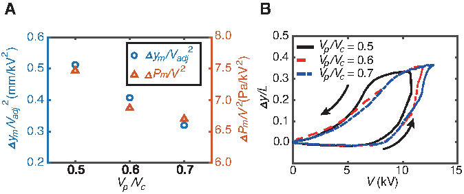
Displacement characteristics with fluid volume change in the actuator.
We observe a hysteresis effect of the displacement, which could be due to the nonlinearity from the fluid in the pouch and flexibility of the electrodes. The electric field and electrostatic force between the electrodes can be changed by the location and amount of the dielectric fluid remained in the supplying pouch; the electrodes of the actuator act as a capacitor. The viscous effect of the dielectric fluid obstructs the flow of the dielectric fluid, which affects the position and quantity of the fluid remained in the supplying pouch at the recovery state.
Because the electrodes are deformable, the zipping area can be different at the same applied voltage. Specifically, when the actuator is in the actuation process, the electrostatic force in the contacting area of the electrodes is enough to enforce the dielectric fluid to flow into the swelling pouch, but the fluid in the area where the electrodes are detached stays in the supplying pouch due to the low electrostatic force. However, when the actuator is in the recovery cycle, the area where the electrodes are already attached is not separated from each other even if the applied voltage decreases because the electrostatic force is high enough to maintain zipping due to the close distance between the electrodes. It may be one of the causes of the hysteresis.
In the inactive state, where the input voltage is increasing until 7.5 kV, tiny variations in the normalized displacement difference are observed. After this state, a sharp increase in the normalized displacement difference occurs along with the voltage increase. In the region where voltage is decreasing, the normalized displacement difference decreases with a gentle curve compared with when the voltage increases. The trend of the normalized displacement difference slightly differs between the
Figure 5 illustrates the phase difference between the input signal and the tip displacement depending on the internal volume of the actuator. The phase difference between the two signals is determined using an algorithm based on zero-crossing detection. The phase delay derived from this method contains information of initial phase lag.
44
The phase difference (φ
y
) tends to increase along with the fluid volume in the pouches. In the cases where the relative fluid volume (

Feature of the phase difference. Phase difference between the input voltage and the displacement of the endpoint on the actuator depending on the fluid volume in the actuator. Color images are available online.
In summary, actuators with lower fluid volumes exert higher displacements than the cases with higher fluid volumes. This means that the case with
Blocking force of the actuator
The force delivered by this actuator can be inferred from the blocking force measured at the edge of the actuator. We conducted experiments to measure the blocking force of the actuator. The input signal is a sine wave with a frequency of 0.1 Hz and amplitude DC 5kV ± AC 5kV. Figure 6 illustrates the blocking forces and pressure in the pouch according to the fluid volume ratio. The blocking force and pressure in the pouch are highest at

Characteristics of the blocking force. Blocking force and pressure inside the pouches of the electrohydraulic actuator for three different fluid volumes in the pouches. Color images are available online.
Effect of actuation frequency
We investigated the actuation characteristics according to the frequency of the input voltage signal. For the electrohydraulic actuator, the local displacement and the pressure in the pouch were measured at three actuation frequencies (f = 0.1, 0.3, and 0.5 Hz). Based on the results in the previous section, we selected the fluid volume of

Actuation performance according to the frequency of the input voltage signal.
Soft gripper using the electrohydraulic actuator
We demonstrate a soft gripper based on the electrohydraulic actuator. The gripper consists of two electrohydraulic actuators and an acrylic body to support the actuators (Fig. 8; Supplementary Fig. S5; Supplementary Movie S3). The gripper can handle fragile objects or delicate materials without complicated control. Figure 8 demonstrates the grasping ability of the electrohydraulic gripper. The gripper can pick up a sphere ball (Supplementary Movie S4). In addition, the gripper can handle delicate materials, such as aluminum foil, a marshmallow, and a balloon in the vertical (Fig. 8A) and horizontal positions (Fig. 8B; Supplementary Movies S5–S7). The results demonstrate a notable ability to grasp objects with various material properties.

Grasping performance.
Conclusion
In this study, we have introduced an actuator harnessing a combination of electrostatic and hydraulic forces without rigid parts. The actuator is a small isolated system, which can easily be installed in a commercial robotic system. The actuator can operate without an external fluid supply source, such as an oil pump. We conducted a series of experiments to determine the characteristics of the unit module of the gripper. The performance of the actuator was altered by changing the volume inside the pouches. In addition, we reported that the actuator with
The result of this study calls attention to several topics in need of further investigation. We need a more thorough understanding of the hysteresis in the actuation to improve the performance and control of the actuator. The proposed electrohydraulic actuator shows low actuation force and speed than electrostatic actuator published by Kellaris et al. 40 For better performance in the actuation force, we can use a dielectric fluid with a higher permittivity. Exploring upgraded design of the actuator can also improve the actuation force. The actuator should achieve the same actuation performance at higher frequency by improvement of the design of the actuator and exploring new materials, such as dielectric fluid having low viscosity.
Footnotes
Author Disclosure Statement
No competing financial interests exist.
Funding Information
This work was supported, in part, by the Convergence Technology Development Program for Bionic Arm through the National Research Foundation of Korea funded by the Ministry of Science, ICT and Future Planning under grant number 2014M3C1B2048419, and, in part, by Korea Institute of Science and Technology Institutional Program under grant number 2E29460.

References
Supplementary Material
Please find the following supplemental material available below.
For Open Access articles published under a Creative Commons License, all supplemental material carries the same license as the article it is associated with.
For non-Open Access articles published, all supplemental material carries a non-exclusive license, and permission requests for re-use of supplemental material or any part of supplemental material shall be sent directly to the copyright owner as specified in the copyright notice associated with the article.
