




Abstract
This article presents the design, fabrication, modeling, and preliminary tests of a bloodworm-inspired soft gripper for universal grasping. The gripper was designed and fabricated based on a toy called water snake wiggly (WSW). The toroidal WSW can evert itself inside-out or outside-in, just like a bloodworm everting its teeth outside to hunt and inside to feed. By driving a WSW rolling itself outside-in to wrap around the items, a bloodworm-inspired gripper was achieved with a flexible and passive form-fitting grasp. To enhance the capability of the gripper, two alternative detachable modules were added to the gripper—a vacuum suction cup for handling objects with smooth nonporous surfaces and an end-needle for taking in and expelling noncorrosive liquids like a syringe. We analyzed the working principles of the gripper and derived the relationship between the gripper's holding force and the objects' scale. Preliminary experiments with a motor-driven gripper prototype were conducted to verify its performance. The experimental results conform well with our theoretical analysis and also indicate the gripper's good universal grasping capacity and reliability in handling a wide range of objects with different surface shapes, geometric dimensions, and stiffness. In addition, the gripper has the unique abilities to pick more than one object during a maneuver, grasp multiple objects in a row without releasing the former ones, and even grasp powdered objects. These have presented a challenge for the existing robotic grippers.
Introduction
Numerous bioinspired robots with impressive performance have been developed in the past decades.1–5 As the key robotic end effector, robotic gripper inspired by nature is always an active area of robotics research. Undoubtedly, the human hand is an attractive ultimate goal that researchers endeavor to replicate due to its dexterity and flexibility. Animal bodies also have an extraordinary capability of grasping that has been mimicked in the design of robotic grippers, such as elephant trunks, octopus tentacles, gecko feet, and a chameleon tongue.
The DLR/HIT Hand II—a multisensory five-fingered dexterous robotic hand with high performance, and other dexterous robotic hands have been developed to provide useful prostheses.6,7 For rigid robotic hands, the dexterity is the result of multiple degrees of freedom, which requires additional actuators and sensors. This makes their designs complex and costly. However, these often lack soft interaction with objects in daily use. With the popularity of soft robotics, soft hands with compliance have been developed. These include RBO Hand 2, 8 SH soft hand designed by Terryn et al., 9 soft prosthetic multifingered hand developed by Zhao et al., 10 and other multifingered soft robotic hands.11–16 These fingers with continuous elastic deformation are molded out of silicon rubber and actuated pneumatically that makes those hands flexible, compliant, robust, inexpensive, and safe. However, due to the low stiffness of the fingers, their capabilities of payload handling and manipulation are limited. Besides, some underactuated robotic hands driven by cables with soft finger pads have also been proposed, which possess the features of being driven by a few actuators, soft interaction, and adaptability to objects with different shapes, for example, Yale OpenHand, 17 shape deposition manufacturing grasper, 18 and the underactuated gripper developed by Manti et al. 19
Brown et al. have developed a jamming gripper, which can grasp a wide range of objects with various geometric shapes and surface properties through variable stiffness and passive form fitting, 20 although it has some limitations—it can't grasp very big, very thin, or very soft objects. Subsequently, the performance of robotic hands was improved by combining with jamming. For example, a variable stiffness hand with the capability of adaptive grasping and robust holding was achieved by integrating soft hand and jamming. 21 The jamming was infused into a soft hand to damp its vibrations. 22 The JamHand, a dexterous hand with minimal actuators, was designed to grasp precisely and with strength, achieved by adding jamming to reduce the hand complexity. 23 Mizushima et al. proposed a multifingered robotic hand with improved object holding stability under disturbances through the jamming transition. 24
Apart from robotic hands, other kinds of bionic grippers have also been explored. Festo AG & Co. KG developed the FlexShapeGripper, a universal gripper modeled on a chameleon's tongue, which can achieve soft and form-fitting gripping for various tasks. 25 Song and Sitti proposed a pneumatic-actuated soft gripper based on gecko-inspired fibrillar structures with adhesion property, which was especially effective at grasping nonplanar three-dimensional (3D) parts. 26 Similarly, Hawkes et al. presented a shear-activated gripper based on a gecko-inspired fibrillar material with adhesive characteristics for lifting soft, brittle, fragile, light, and even very heavy objects. 27 Besides, the OctArm inspired by elephant trunk can grasp a wide range of objects with a variety of sizes and payloads with its winding28,29; however, it can't manipulate very small objects compared to its size.
The grippers mentioned above were mainly designed to cover daily tasks with limited size and weight, thus special grippers for micro or heavy objects were proposed. The piezoelectric actuator has been used in microgrippers due to its capability of generating micron-range displacements, as well as high forces. For instance, Jain et al. designed a compliant piezoelectric-actuated microgripper for handling miniature parts in the robotic microassembly. 30 A parallel microgripper using bending piezoelectric bimorph actuators was presented for precise micromanipulation tasks with objects down to 50 μm in size by El-Sayed et al. 31 Electrostatic grippers with intrinsic electroadhesion forces from electrostatic actuation were developed to handle flexible films in simulated microgravity, 32 as well as to manipulate deformable and fragile objects in daily tasks.33,34 Besides, dielectric elastomer-based grippers were also presented for micromanipulation by Araromi et al. 35 and Shian et al. 36 However, a considerable high voltage (up to 1 kV or even higher) is needed to engage the electrostatic adhesion or to actuate the dielectric elastomer, which is uncommon in daily life. As to large and heavy objects, the vacuum grippers are notably diffused. 37 PR10, an electrical vacuum gripper developed by Purple Robotics, Inc., can handle the payload of up to 10 kg with varying-size workpieces from 10 × 10 mm to 500 × 500 mm. 38
It is ineffective for rigid grippers to perform compliant grasping tasks unless sensors are added to improve its interaction ability and in-hand manipulation, inevitably increasing the total cost. In contrast, the pneumatic actuated soft grippers, molded with inexpensive silicon rubber, address the issue of compliant grasping while reducing costs. However, it introduces other problems such as low stiffness and bulky air source, which make these payload limited and unportable. The jamming grippers can adjust between soft and rigid, but they are pneumatically actuated. It is inevitable for jamming grippers to prepress onto the objects before grasping, which impedes their capability to grasp soft objects, such as cotton balls and soft facial tissues. More importantly, the pneumatic-actuated grippers are impractical for use in vacuum and high-pressure environments, such as outer space and deep sea.
To address some of these issues on robotic grippers mentioned above, in this article, we proposed a bloodworm-inspired soft gripper for universal grasping, which can be incorporated with detachable modules to extend its grasping range. This soft gripper can envelop an entire object or part of a target object for self-adaptive grasping. The results from our study reveal its significant universal grasping capacity and reliability in grasping a variety of objects with a broad range of stiffness, geometry, and states. In this article, we present the mechanical design, fabrication, and theoretical analysis of a bloodworm-inspired soft gripper. Preliminary experiments were carried out to verify its universal grasping feasibility and efficiency.
Materials and Methods
Inspiration and motivation
A bloodworm (Glycera Dibranchiata), of general morphology, hides its proboscis with jaw inside the body as shown in Figure 1a and c. 39 To catch a prey, it everts (turns inside out) part of its body (as shown in Fig. 1b 40 ) until everting its entire mouth into the open air through the distal end of its body to shoot its proboscis out (as shown in Fig. 1d 40 ). After catching the prey, it turns its body outside-in to pull its mouth with prey back into the body for feeding. With its inverted body holding the prey tightly, a bloodworm can enjoy its prey over time with no worry about fleeing or dropping of the prey. The bloodworm has unique anatomy and motion, which can be mimicked by a water snake wiggly (WSW), as shown in Figure 2e. Its everting motion can capture objects tightly just like the bloodworm holding a prey, which is very appropriate for a robotic gripper and inspires us to fabricate a bloodworm-inspired gripper with a WSW.

A bloodworm with different morphologies.

Schematic of the fabrication process of a WSW.
We discovered that a WSW could mimic the everting motion of a bloodworm to act as a gripper with the help of a pen and two hands as shown in Figure 3. The pen is inserted into the center of a WSW with the inner membrane tightly wrapping around the pen, while the outer membrane is held by the right hand. Consequently, the friction between the inner membrane and the pen can guarantee them moving without relative sliding along the longitudinal axis. The left hand holds the pen to stay still, while the right hand holds the outer membrane and moves toward the stapler (object) (There is also no relative sliding between the outer membrane and the right hand.). Simultaneously, the outer membrane turns inside to become the inner membrane on the proximal-object side, as well as envelops the stapler with a bloodworm-like everting motion. Finally, the stapler is gripped by the WSW and lifted away from the ground. This motivates us to design a bloodworm-inspired robotic gripper fabricated with a WSW.

A manual-actuated gripper made of a WSW and a pen:
WSW and its fabrication
As a toy, the fun of playing with a WSW stems from its difficulty in grasping, because of silicon membrane wrapped flexible exterior and fluid-filled soft interior. The raw cylindrical silicone gel in Figure 2a has a wall thickness of t and a diameter of dn. It is folded in half from its longitudinal center to get two concentric cylinders (Inner membrane tube and outer membrane tube), then the noncompressible liquid is filled in the space between the inner and outer membrane tubes as shown in Figure 2b. The elastic membrane will expand with liquid filling due to the pressure and gravity of the liquid. Finally, the two ends from the inner and outer membranes overlap and seal to get a WSW as shown in Figure 2c. Ideally, the WSW is in the shape of a long toroid filled with liquid and has smooth curved ends, as shown in Figure 2d. However, the inner membrane tube is closely packed together with wrinkles and buckles and almost does not have an inner radius (because the original dn-diameter cylindrical silicone gel gets overlapped to form an inner diameter of almost zero), while the outer membrane extends under tension due to the liquid pressure. Its real ends take irregular shapes because of the geometric shapes and liquid pressure as shown in Figure 2e. As a result, the toroid WSW can evert itself inside-out and outside-in just like the motions of a bloodworm. These characteristics have been successfully used in amoeboid motility inspired whole skin locomotion robot presented by Hong et al. 41 and a growing robot developed by Hawkes et al., 42 a spherical self-adaptive gripper proposed by Zhu et al., 43 and a swallowing robot designed by Li et al. 44
Design and fabrication of the bloodworm-inspired gripper
A direct way to realize a bloodworm-inspired gripper with a WSW is to replace the hands in Figure 3 with an actuator and accessory components such as transmission and holding parts. To this end, we proposed a simplified concept design of the bloodworm-inspired gripper as shown in Figure 3e. The supporting tube maps the right hand, and the central rod simulates the pen. Besides, an actuator is needed to drive the supporting tube and the central rod moving relative to each other to drive the WSW everting.
The elaborate design of the bloodworm-inspired soft gripper fabricated with a WSW is depicted in Figure 4 (left). A stepper motor (maximum speed: nmax = 500 r/min) is chosen as the actuator due to its ease of use and a ball screw (helical pitch: 2 mm) is used for transmission, taking compactness and lightweight as performance considerations. A bloodworm cannot swallow much bigger prey than its body size and so does the soft gripper. The WSW rolling inside the supporting tube can be regarded as a low-friction piston like the fluid-tendon soft actuator designed by Whitney et al., 45 which can compress air within the enclosed space. Then, we introduced a suction cup as the first detachable module for grasping bigger objects. Furthermore, we designed a 3D-printed funnel-shaped structure with a hole in its tip called “end-needle” as the second detachable module to extend the gripper's ability to take in and expel liquid like a syringe.

The detailed design configuration and a fabricated prototype of the bloodworm-inspired soft gripper.
Other components include a 3D-printed supporting tube for holding and supporting the WSW, a 3D-printed motor frame for fixing the motor, and three steel rods for guiding the supporting tube. The supporting tube is a tube with the proximal end open and distal end closed and embedded with a ball bearing for mechanical matching with the leadscrew. Besides, the open end of the supporting tube is the carrier where the detachable modules are mounted, if necessary, and serves as the gate where the WSW rolls fully in or partly out of the supporting tube for assembling and gripping. The three slick steel rods with a diameter of 4 mm are evenly fixed on the circumferential edge of the motor frame after passing through the guiding holes on the supporting tube as shown in Figure 4. They are used to prevent the supporting tube from rotating with the motor frame and to guide the supporting tube moving along the longitudinal direction.
The leadscrew plays the role of the pen (or the central rod) in Figure 3, as well as a part of the transmission mechanism. One end of the leadscrew is fixed on the shaft of the motor, and the other end is inserted into the center of the WSW and linked with the inner membrane of the WSW by a 3D-printed connector. This guarantees the inner membrane of the WSW to synchronously move with the leadscrew along the longitudinal direction and blocks the venting of the inner membrane tube for achieving a closed space. A bearing is mounted between the tip of the leadscrew and the connector to keep the relative rotation around the central axis while preventing the relative slipping along the longitudinal direction between the leadscrew and the inner membrane of the WSW. However, the relative rotation may damage the inner membrane because the proximal inner membrane wraps and tightly presses on the leadscrew due to the liquid pressure. To address this issue, a free low-stiffness compression spring with a little bigger diameter compared with the leadscrew is sleeved over the leadscrew. The spring spans from the connector to the matched ball bearing to separate the inner membrane from the surface of the leadscrew. Meanwhile, the tensioned outer membrane of the WSW is pressed on the inner wall of the supporting tube by the liquid pressure, which guarantees WSW pure rolling inside the supporting tube.
It is noticed that the inner diameter of the supporting tube must be designed appropriately according to the natural outer diameter of the WSW. This assures the WSW's outer membrane to attach tightly on the inner wall of the supporting tube to achieve the pure rolling. Theoretically, the inner diameter of the supporting tube (dsi) should be smaller than the natural outer diameter of the WSW (d). The soft WSW can stretch along its longitudinal direction while contracting along its radial direction under the geometry restriction of the supporting tube. So, the WSW will seamlessly fit the inner wall of the supporting tube passively, benefiting from the incompressibility and fluidity of the liquid and the elasticity of the membrane. In practice, however, dsi cannot be so small that it exceeds the malleability limits of the WSW, otherwise, the outer membrane will attach to the inner wall of the supporting tube with multioverlapped folds and is likely to be torn by the pressure during operation. Meanwhile, it is not practical if the dsi is too close to d, because the resilience of the membrane is too small to produce enough pressure (i.e., friction) between the membrane and the inner wall of the supporting tube to assure pure rolling movement. Finally, after trial and error, we empirically chose d = dsi+1 mm in our design.
As the ball screw was used as the transmission mechanism, we had to consider either the leadscrew or the ball bearing being the actuated part during operation. The motion of the soft gripper is illustrated in Figure 5. The gripper's initial state is shown in Figure 5a, and the area S is selected as the observation area with 4 marked points: A, B, C, and D. A is on the junction of the WSW and the leadscrew. B is on the front of the WSW (B′ or B″ is the fixed point on the WSW related to B to indicate the local movement of the WSW's membrane, while B1 and B2 are always the related most front point of the WSW to indicate the macroscopic movement of the whole WSW). C is on the free end of the leadscrew, and D is on the left end of the supporting tube. A′/A″, B′/B″, C′/C″, and D′/D″ present the final position of the related points after moving by driving the leadscrew/supporting tube. In Figure 5b, the leadscrew is pulled back to drive the gripper performing the gripping motion, while the supporting tube stays still (Comparing D with D′). As a result, the WSW performs the retreating movement (Comparing B1 with B). To execute gripping motion, the supporting tube is pushed forward to drive the gripper in Figure 5c. Contrary to Figure 5b, the WSW advances (Comparing B2 with B), while the leadscrew stays still (Comparing C with C″). In brief, to perform the gripping motion, the WSW (main executive body) moves backward in Figure 5b while moves forward in Figure 5c.
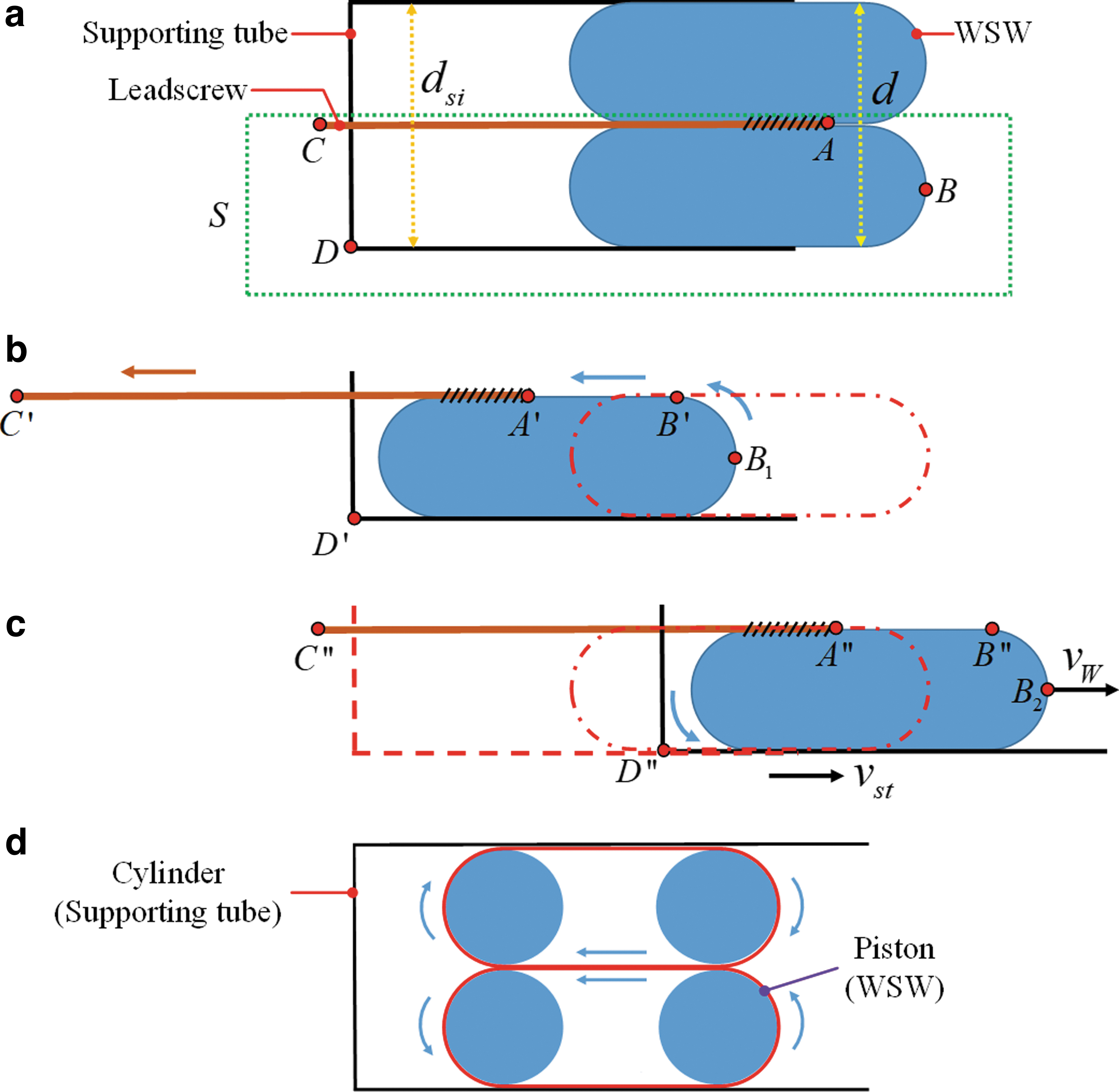
The cross-sectional area illustrations of the bloodworm-inspired soft gripper's motion:
Taking the robot arm into account, during gripping operation, first, the robot arm conveys the gripper to the object (the gripper's executive body almost touching the object), then the gripper exerts gripping motion to grasp the object. However, during gripping operation, the robot arm has to keep moving forward to counteract the inherent backward motion of the gripper, as well as pull the gripper moving forward to keep the WSW contacting with the object in Figure 5b, while in Figure 5c, the robot arm can stay still because the inherent forward motion of the gripper can keep the WSW contacting with the object. As a result, we chose Figure 5c in our design (the supporting tube as the actuated part) to simplify the operating motion and save resources. As for the velocity of the WSW (vW), it can be calculated using the linear velocity of the actuated supporting tube (vst. i.e., the linear velocity of the ball screw) from Figure 5c:
In this article, we mentioned that the WSW acts as a low-friction piston in the supporting tube above. In this study, we must underline that the exact meaning of “low-friction” is that there is no sliding friction between the WSW and the supporting tube, but the WSW only rolls purely in the supporting tube under the influence of static friction between them as shown in Figure 5d. The membrane of the WSW rolls purely on the inner surface of the supporting tube, just like the continuous track moving on land. Compared to the traditional piston which purely slides in the cylinder, the low-friction piston (WSW) can avoid the generation of sliding friction. Therefore, the life of the machine will be greatly prolonged by the avoidance of sliding friction between moving parts.
Basing on this design strategy, a bloodworm-inspired soft gripper prototype driven by a motor was fabricated with a WSW as shown in Figure 4 (right). Its parameters are selected according to the size of the WSW. The WSW has an original total length of l = 100 mm and an outer diameter of d = 54 mm. Significantly, the inner diameter of the supporting tube is designed to be 53 mm according to the design principle to ensure that the gripper is working to its full potential. The length of the supporting tube is 120 mm, and the extra 20 mm is spared for the spring when being compressed to its shortest length, as well as for improving the closed space for the detachable modules.
Gripping behavior analysis of the bloodworm-inspired gripper
Unlike the bloodworm, which uses the individual claw to grasp the objects and the everting motion of skin to hold the objects, the bloodworm-inspired gripper does not have a claw and has to both grasp and hold the objects only using the everting motion of the membrane. To better understand the gasping behavior of the bloodworm-inspired gripper, its gripping principles are studied.
We sort the gripping behavior of the bloodworm-inspired gripper into two working principles. The first one is called the “swallow” principle. The gripper everts to adaptively wrap on the surface of the objects with pressure, benefiting from its flexibility and fluidity of the liquid. As a result, the static friction from the surface contact between the membrane and the objects or the geometric constraints from interlocking facilitate the gripper to grasp and hold the objects as shown in Figure 6a and b. This working principle is similar to the gripping modes of the jamming gripper. 46 However, unlike the jamming gripper which presses on the objects first and then changes its stiffness to grasp the object, our soft gripper can grip the objects without stiffness change and with smaller preload force, due to its swallow-like gripping.

Schematic of the working principle of the bloodworm-inspired gripper.
For the “swallow” method, the gripper has to produce enough friction force (f) between the membrane and the object's surface to balance the weight of the object (mg) as shown in Figure 6a:
The derivation of f is elaborated in the following Static Model of the Bloodworm-Inspired Gripper section.
Consequently, with the “swallow” method, the soft universal gripper can grasp a wide range of objects with a variety of shapes, stiffness, weight, and fragility, including objects that are traditionally challenging for conventional grippers and other universal grippers. This is demonstrated in the following Experiments and Results section. However, these objects must have an appropriately small scale or with a small-scale part so that the gripper can hold the whole or part of the object to apply the friction force. Otherwise, the gripper can try to grasp the objects using the other working principle.
The other working principle is the octopus sucker, which has been used to design a vacuum gripper by Tomokazu et al.
47
Most vacuum suction cups are achieved using the pressure difference between the enclosed cavity and the atmospheric pressure, that is, to decrease the pressure in the closed cavity. The relationship of volume (V) and pressure (P) of the closed cavity obeys the following ideal gas law:
where P, V, and T are the pressure, volume, and absolute temperature, respectively, n is the number of moles of gas, and R is the gas constant.
Under the constant temperature conditions (T = constant), the ideal gas law gives two practical methods to decompress a closed cavity: (1) decrease the number of moles of gas n and (2) increase the volume of the cavity V.
The method (1) is generally used in traditional industrial vacuum suction cups using a vacuum pump or ejector to drive the gas out of the closed cavity to decrease the number of moles of gas in it. Alternatively, the bloodworm-inspired gripper can achieve vacuum suction adhesion using the method (2) without needing a vacuum pump or ejector owing to the low-friction piston-like characteristics of the WSW when it rolls in the supporting tube. This also makes it possible to achieve a suction cup gripper with the detachable suction cup module only driven by the motor and without any vacuum pump or ejector, as shown in Figure 6d. The gripper's working process with the octopus sucker principle is described in Figure 6c. After the tip of the WSW contacting with the object, a closed cavity forms between the WSW and the object. Then, a constant mole of gas (n) is sealed in the closed cavity with a volume of V0 and almost the same pressure as the atmosphere pa (p0 = pa). When the gripper is actuated to evert the WSW rolling inside the supporting tube, the tip membrane rolls outside-in, and the supporting tube goes downward. Simultaneously, the membrane presses on the object forming enough friction between the membrane and the object's surface to prevent the membrane from sliding on the object's surface. It should be emphasized, however, that the whole gripper should be driven upward appropriately by the handling system to counteract the inherent advancing motion of the WSW when gripping with the octopus sucker principle so that the curved inner membrane is straightened as shown in Figure 6c middle. Consequently, the volume of the closed cavity between the WSW and object is extended to Vf (Vf > V0), and the pressure within it drops to p1 (p1 < pa) according to the ideal gas law. So, the gripper can adhere to the object like an octopus sucker.
Under the constant temperature (T = constant) and ideal WSW configuration assumptions, as shown in Figure 6, the force balance between the object's weight (m1g) and the applied force (f1) due to the pressure difference induced by the “octopus sucker” effect can be derived as:
where n (the number of moles of gas in the cavity), R (the gas constant), and T (absolute temperature) are constants, Δp is the pressure difference of before and after grasping, and S is the effective area where the pressure difference is applied.
Simultaneously, we can check the deformation of the membrane by deriving its length change (ΔL) in the longitudinal direction.
However, the deformation ΔL of the membrane is limited to the membrane tension, which is limited by the membrane's stiffness. So h1 is limited by the membrane's stiffness, and thus, the applied force f1 on the object is limited by the membrane's stiffness according to Equations (6) and (7).
When the actuator moves by Δx, the increased volume ΔV in Figure 6c can be calculated as:
For the detachable suction cup, as shown in Figure 6d, the increased volume ΔV2 can be calculated according to Equation (1):
In practice,
With the octopus sucker principle, the soft gripper is effective at gripping objects with smooth nonporous surfaces and flat geometry just like a suction cup, as shown in Figure 8g. However, it can also suck objects with a smooth nonflat surface, as well as objects with the same or smaller size compared to the gripper, profiting from the adaptability and flexibility of the WSW as shown in Figure 8f. This is almost impossible to be completed by the detachable suction cup. In contrast, the load capacity of the inherent octopus sucker is much less compared with the detachable suction cup, as analyzed above. So, the detachable module of the suction cup can be attached to offset the shortcoming of the inherent octopus sucker on load capacity and also to extend the ability of the whole gripper. Besides, the gripper with the detachable module of the end needle works just like a syringe where the WSW plays the role of a low-friction piston to change the pressure in the closed cavity between the WSW and the end needle for taking in and expelling the liquid. It is noticeable that the attached suction cup module does not impede the general gripping function of the WSW, while the attached end needle will cost the WSW its general gripping ability. In addition, the WSW plays the role of a low-friction piston when the detachable modules are working.

The bloodworm-inspired soft gripper for picking different objects, including rigid objects, fragile objects, soft objects, and liquid in daily life with different gripping principles.
Static model of the bloodworm-inspired gripper
To study the ability of the soft gripper quantitatively, its theoretical static model is developed for describing the relationship between the object wrapped and the holding force of the gripper. The nomenclature used in this article is presented in Appendix Table A1. First, we assume that (1) the WSW has an ideally regular symmetry structure: a straight line with two round edges, which can be depicted by revolving a straight slot around its longitudinal line as shown in Figure 7a. (2) The internal tension of the WSW's membrane can be decomposed in two subdivisions: one is in the longitudinal cross-sectional area as shown in Figure 7b, and the other is in the latitudinal cross-sectional area as shown in Figure 7c. (3) The membrane in the cross-sectional area analysis can be seen as a closed elastic string with a width element (dwl and dwr) and with an identical internal force (Tl and Tr) subjecting to Hooke's law. (4) Ignore the gravity of the liquid and membrane. (5) To simplify the analysis, we assume that the object only contacts with the WSW at the general line part of the inner membrane, and the object is entirely wrapped by the inner membrane as shown in Figure 7d. (6) For the general use of the model, we ignore the diameter difference (1 mm) between the natural WSW and the inner wall of the supporting tube. (7) The impact on the membrane's tension produced by the friction between the supporting tube and outer membrane or between the inner membrane or between the object and inner membrane is ignored so that the membrane has an identical tension in the cross-sectional area like a tensional string.

Ideal structural illustration of the WSW.
In Figure 7a, a single WSW is divided into four regions based on the tension distribution in the tangential direction of the membrane along the latitudinal cross-section. The regions' boundaries are located on the membrane circle having the same diameter dn with the raw cylindrical silicone gel shown in Figure 2a and the joint between the straight line and round, respectively. Assisted by Figure 7c, the following conclusions can be reached:
The membrane in Region I does not have any tension in the tangential direction, that is:
Because its apparent circumference is not more than the natural circumference πdn of the WSW's raw material shown in Figure 2a, no extension exists in the membrane's tangential direction in Region I.
The membrane's tension in the tangential direction of Region III is isotropic. The relationship between the tangential direction tension Tr and the distributed pressure difference p in the normal direction can be found by integrating p over a segment of angle θ and summing the forces 48 :
where p = pl-po, pl is the inner liquid's pressure on the membrane, and po is the outer environmental pressure on the membrane.
Then, the elastic stiffness kr of the membrane element with width dwr along the latitudinal cross-sectional area can be derived according to Hooke's law:
The membrane's tangential direction tension in region II and IV (two symmetrical regions) consecutively declines from
Thus, the membrane's tension Tr can be written as a function of α according to Equations (12), (13) and Hooke's law:

Besides, when holding an object, the inner membrane will produce tension if it is squeezed by the object to extend a circumference c which is bigger than the raw cylindrical silicone gel's circumference πdn (c > πdn) in any latitudinal cross-sectional area. In this case, the relating membrane's tension property transforms from Region I to Region II/IV; the tangential direction tension Tro of that inner membrane can be derived from Equation (14) as follows:
Therefore, after holding an object, only part of Region I may get transformation and the rest is still subjected to Equation (10), while Equations (11) and (14) are still suitable for Region III and II/IV.
As for the membrane's tension Tl along the longitudinal cross-sectional area in Figure 7b, it can be calculated by integrating p over the angle π:
We have regarded the membrane circle as a closed elastic string with a width element dwl in Figure 7b. Then, we can derive the elastic stiffness kl of the membrane element with width dwl along the longitudinal cross-sectional area from the relationship between the membrane's tension Tl and the circumference L of the membrane circle according to Hooke's law:
where L0 is the natural circumference length of the membrane along the longitudinal cross-sectional area without the liquid pressure, l0 is the length of the single line part shown in Figure 7b.
To derive the holding force due to friction, we take a cylindrical object with a diameter of dc (dc > dn) and a height of hc as shown in Figure 7d. The gripper entirely holds the cylinder due to the friction force. Tcl is the membrane element tension in the longitudinal cross-sectional area, and γ is the angle between the direction of Tcl and the top/bottom base of the cylinder. We assume that the total length change of the membrane element in the longitudinal direction is Δxl (Δxl = Δx0 + Δx, where Δx0 is caused by the fabrication of the WSW and Δx is caused by the held object.). Then Tcl = Δxlkl. So, we can calculate the normal force FNl applied to the cylinder by the membrane in the longitudinal cross-sectional area:
Tcr is the membrane element tension in the latitudinal cross-sectional area, and the length change of the membrane element in the latitudinal direction is Δxr = πdc-πdn. Then Tcr = Δxrkr. So, we can calculate the normal force FNr applied on the cylinder by the membrane in the latitudinal direction:
where Scr is the effective area where the pressure pcr applies: Scr = πdchc. pcr is the pressure applied to the cylinder due to the membrane tension in the latitudinal direction and it can be derived according to Equation (11).
Thus, we can derive the total normal force FN applied on the cylinder surface by the membrane:
With the constant configuration of the cylinder, if the coefficient of friction between the cylinder surface and the membrane is μ, then the maximum friction fmax produced by the gripper to steadily hold the highest weight of the cylinder mmax can be expressed as:
So, within the tension range of the membrane and under the gripper entirely holding the object conditions, the biggest load capacity mmax of the gripper with the “swallow” principle can be derived as:
It is noticeable that if the membrane is with an isotropic material, it will have an identical elastic stiffness k in any direction, that is:
Then, we get the relationship between the length and diameter of the WSW:
Based on Equation (22), we can summarize the influence of the geometric parameters of the WSW on the gripper: (1) When grasping a certain object, the gripper can generate a larger holding force if the WSW is fabricated with a larger outer membrane diameter d as shown in Figure 2d. Because under the constant dn, Δx, kr, and kl conditions, increasing d will lead to the increase of p according to Equation (12), as well as the increase of l0 according to Equation (17), which will increase FNl according to Equation (18) but make no difference on FNr according to Equation (19). This will increase FN according to Equation (21), that is, increase the holding force according to Equation (22). Besides, d also affects the load capacity of the gripper. Because the diameter of the rigid supporting tube relies on d and larger d means that the gripper can hold a larger object or part of the object so that the gripper can generate larger holding force to grasp larger and heavier objects. (2) The stiffness of the membrane (kr and kl) also has a positive impact on the holding force of the gripper according to Equations (18) and (19). The stiffness is the inherent feature of the membrane, so the parameters of the membrane (material, thickness, etc.) can affect the holding force. (3) The larger length l of the WSW means that the gripper can hold a larger part of the object, so the gripper will have a larger load capacity. In contrast, the gripper will have more space to store objects and can grasp objects continuously without release of the former grasped ones, which means that the gripper has a stronger capacity for continuous grasping. These conclusions are deduced from Equation (22) to help readers to design the gripper for their own purposes not verified through experiments in the article.
For a specific gripper, d, l0, L0, and dn are constants. p is also decided if the application environment is assigned. Then Equation (22) predicts that: (1) the holding force (i.e., the maximum friction fmax) increases with the friction coefficient (μ) between the membrane and the surface of the object. (2) The holding force increases with the diameter (dc) of the cylinder. (3) The holding force increases with the height (hc) of the cylinder. These were proven through experiments shown in Figures 11 and 12.

The holding force comparison of the stage and spherical objects with different sizes.

The gripper's performance on gripping cylindrical objects with the same diameter and the fitted straight line of holding force.
Moreover, according to the static model, the membrane tension balances the inner liquid's pressure, as well as the outer environmental pressure, and the WSW conforms to the hydrostatic skeleton theory. As a result, the membrane can adapt to any of the environments, including the high-pressure environment of the deep sea and the vacuum environment of the outer space. So, the soft gripper has the potential for working in these environments as well.
Experiments and Results
Object gripping capability
To verify the performance and the feasibility of the proposed bloodworm-inspired soft gripper based on WSW, the motor-driven prototype was tested to validate its universal grasping capability of picking up daily objects ranging from powdered ground coffee to raw eggs, from soft and light facial tissues to rigid cellphones. Meanwhile, its multiple objects' grasping ability, as well as its detachable modules (suction cup and end needle), was also characterized.
Our soft gripper is particularly well-suited for grasping irregular-shaped objects such as a key, a watch, a pair of pliers, and a 250 mL can of Pepsi (260 g) as shown in Figure 8a–d, as well as soft and delicate objects such as towel, raw eggs, facial tissue, and bagged milk, as shown in Figure 8e, f, and j–l, owing to the fluidity of the liquid and the soft membrane of the compliant WSW. The rigid grippers, such as robotic hands, have to be integrated with sensors for safely grasping fragile and soft objects. However, our soft gripper can overcome this difficulty to achieve flexible and safe grasping without sensors profiting from its inherent flexibility, especially for grasping a flat facial tissue, a suspending facial tissue, and the bagged milk (extremely soft and deformable objects), as shown in Figure 8j–l. This is even a great challenge for jamming grippers due to the required considerable preload force. 20 It should be noticed that like most grippers, the gripper requires a certain tilted angle to “catch” the rigid objects with irregular profiles to improve the grasp reliability. However, the gripper can easily “catch” the flexible objects with a wider range of tilted angles, such as the tissue paper and towel as shown in Figure 8e, j, k, thanks to the lightweight and more compliance of the flexible objects.
The soft gripper can also grip multiple objects, as well as small objects, as shown in Figure 8m and n. To verify it, M4 nuts with a thickness of 3.2 mm and a maximum diameter of 7.6 mm were chosen as the objects. The gripper can not only grasp a single M4 nut but also pick up 13 of 15 M4 nuts in one grasping session. Besides, we were surprised to observe the gripper's capacity of collecting powdered objects, such as the powdered coffee, as shown in Figure 8i. This capacity has not been achieved in the literature of grippers in our knowledge. Even though the quantity of powdered object grasped is limited, it demonstrates the soft gripper's ability to grasp powdered objects just like human hands.
The vacuum suction cups are widely used in industry for handling the objects with smooth nonporous surfaces by establishing a good seal between the suction cup and the object. The soft gripper was equipped with the detachable module of a silicone suction cup to transform the gripper to be a professional suction cup for grasping objects with a smooth surface, as shown in Figure 8h. As a contrast, and to validate its working principle of octopus sucker, the soft gripper was used to grasp a cellphone (184 g) with a smooth surface using vacuum absorbing, as shown in Figure 8g. Another detachable module—the end needle—was tested to take in and expel red water like a syringe, as shown in Figure 8o–r. In this design, the so-called octopus sucker, the detachable suction cup, and the detachable syringe share the same working principle of vacuum adhesion realized by extending the volume of the closed cavity.
Holding force
To assess the holding capacity of the soft gripper quantitatively, we designed force-test protocols to obtain the holding force. The experimental setup is shown in Figure 9a. The object was connected to a pull–press force sensor fixed on the mounting base, so the force sensor can measure the gripper's preload force and holding force during the experiments. The soft gripper was installed at the end of a robotic arm (UR10; Universal Robots, Inc., Danish), so the gripper can be pulled vertically up and apart from the object. During each experimental trial, we first moved the gripper vertically down to almost touching the object by the robotic arm. Then the test started; the soft gripper itself drove the WSW moving downward to envelop and grasp the object until it totally held the object (gripping phase). This phase also embodied the advantage of the gripping motion accompanying the advancing movement of the WSW by taking the supporting tube as the actuated part. After the gripper stopped moving, it was lifted upward by the robotic arm at a constant speed of 18 mm/s until the gripper was completely apart from the object to finish a single trial (apart phase).

Experimental setup for the holding force measurement.
During each gripping test, the force data from the force sensor were recorded at a sampling rate of 2500 Hz. And the raw data were processed through a low-pass digital Butterworth filter. For each test, the measured force shared almost the same trend as shown in Figure 10 (red curve), which depicts the interaction force between the gripper and the object in the vertical direction. It is worth noting that its sign only indicates the direction of the force applying on the object, while its absolute value describes the magnitude of the force. The red curve between the start point and point A presents the gripping phase, and the apart phase is depicted by the red curve from point A to point E. It is obvious that there are periodic oscillations of the force in the gripping phase. This may be caused by the axis straightness error of the leadscrew, as well as the gap between the steel rods and their guiding holes on the supporting tube, which led to the slight swing of the gripper along its radial direction.
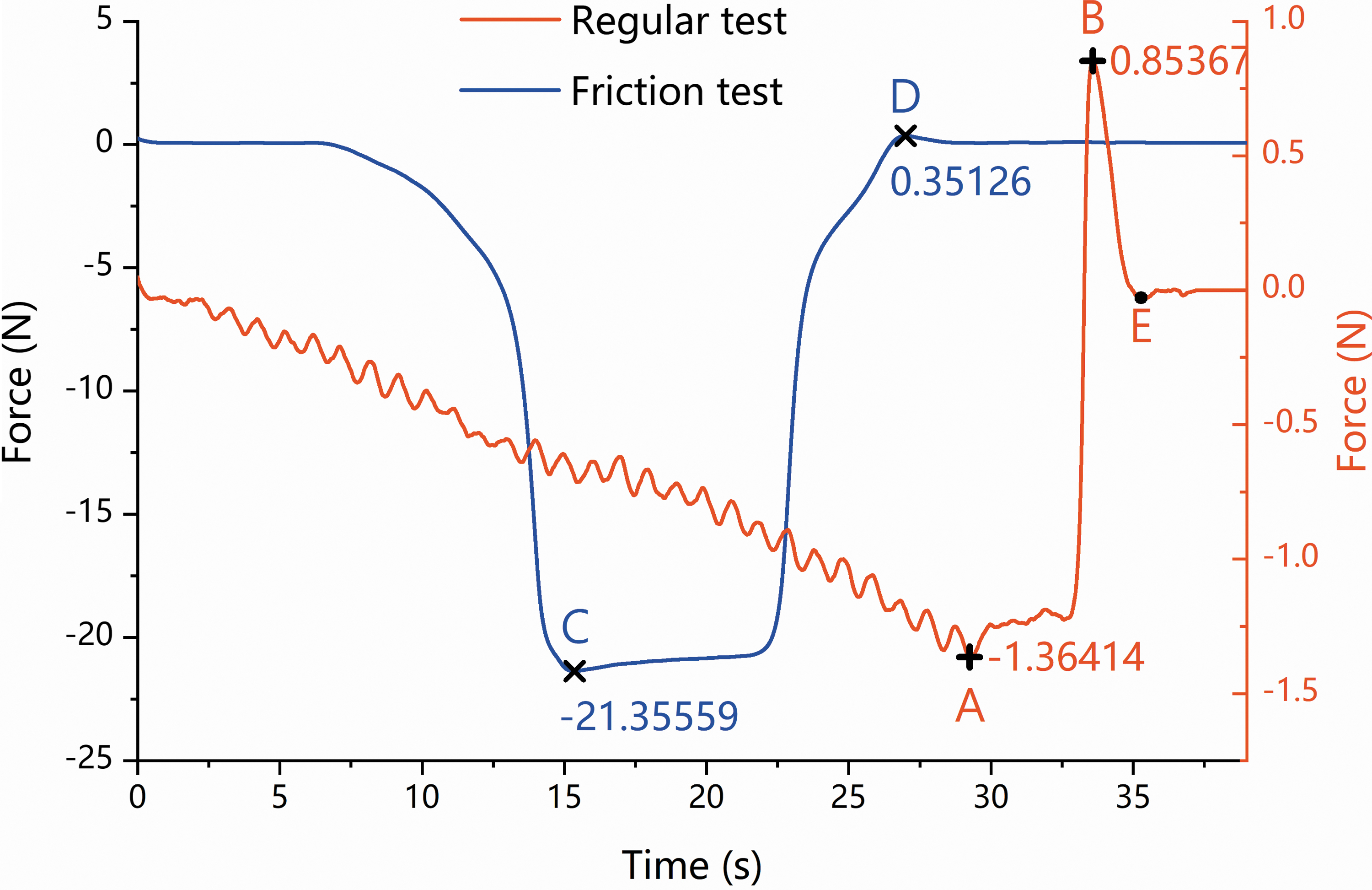
The measured force of regular test and friction test for the resin spherical object with a diameter of 25 mm.
During the gripping phase, ignoring the oscillations, the force decreases (absolute value increases) along the gripper moving down because the gripper pressed on the object was moving downward. We define the negative force as preload force, then the maximum preload force (absolute value) occurred at the end of the gripping phase (point A). During the apart phase, the preload force (absolute value) decreased to 0 at first, and then the force increased to its peak (point B) because the gripper was being lifted upward by the robotic arm while holding the object. Point B should be the start moment of dynamical friction that occurred between the gripper and the object, and the dynamical friction force lasted for the whole next descent period. During this descent period, the object's volume held by the gripper decreased rapidly along with the gripper moving upward to separate from the fixed object. After the gripper was completely apart from the object, the force returns to its initial value zero (point E). We define the maximum friction force (point B) as the holding force.
We totally tested 70 3D-printed objects of two different materials—nylon (black) and resin (white), where the friction coefficient between the surface of nylon (μn) and WSW membrane is bigger than that between the surface of resin (μr) and WSW membrane. The objects have three profiles—sphere, stage, and cylinder. For the spherical and stage objects, each of them has five different sizes (with diameters of 15, 20, 25, 30, and 35 mm), as shown in Figure 9b. For the cylindrical objects, they are with 5 different diameters (15, 20, 25, 30, and 35 mm) for each height and 5 different heights (10, 15, 20, 25, and 30 mm) for each diameter, totally 25 different sizes, part of them are shown in Figure 9b. For each object, we conducted holding test (regular test) thrice repeatedly to reduce erroneous data. We statistically processed the filtered experimental data of 3 tests for each object to acquire the mean ± standard deviation (mean ± SD) value of its holding force and maximum preload force. Figure 11a and b depicts the holding force and maximum preload force of the stage objects and spherical objects by mean ± SD, respectively. The red color indicates the nylon object, and the blue color indicates the resin object. The points indicate the mean force, while the bar indicates the SD.
For stage and spherical objects, Figure 11 demonstrates that with the same profile and material, bigger the size the object is with, the larger holding force and maximum preload force the gripper can generate. Figure 11 also illustrates that with the same size and profile, the objects with a bigger friction coefficient of surface yield larger holding force and maximum preload force than the smaller ones. This conforms well with our analysis in Equation (26)/(22). It manifests that both the size and the friction coefficient of surface of the object have a positive effect on increasing the gripper's holding force. So, we can infer that the overall holding force of the gripper can be improved by increasing the roughness of the WSW membrane, that is, increasing the friction coefficient of the surface between the WSW membrane and objects from the gripper's perspective.
It is noticed that the holding force between the nylon stage and nylon sphere with the same diameter is similar. However, for the resin stage and resin sphere, the holding force is very different. This difference may be due to the difference of their profiles. The hard edges of the stage help produce geometric constraints from interlocking, as shown in Figure 6b, compared to the uniform rounded profile of the sphere. When grasping objects with a low coefficient of friction between the surface and the membrane (such as the resin objects), the effect of the geometric constraints from interlocking will dominate the holding force instead of the size of the objects. Therefore, the holding force of the resin sphere is much smaller compared with the resin stage.
For the cylindrical objects, the holding force Fh should be equal with the maximum friction force fmax according to Equation (22).
where Δxl = Δx0 + Δx and Δx can be written as the function of hc and dc according to the change of the WSW's volume after totally holding the object, as shown in Figure 7d.
where f(dc,hc) presents a function with dc and hc as independent variables. Ideally, when the length of the WSW l is much bigger than the height of the cylinder hc, f(dc,hc) and γ are only related to dc, that is f(dc,hc) = f1(dc), cosγ = f2(dc). So, when gripping different objects, in Equation (26), μ, dc, and hc are independent variables, while the other symbols are constants for a certain gripper. Then the holding force Fh can be written as a function of μ, dc, and hc.
where A, B, C, D, and E are constants determined by the parameters of the gripper. f1(dc) and f2(dc) are functions with dc as independent variables.
Equation (28) indicates that for two objects with the same size and different materials, the ratio of Fh of the two objects equals the ratio of their friction coefficient of surface.
The experiment results of the 50 cylindrical objects (25 nylon objects vs. 25 resin objects) are listed in Table 1. The mean holding force is chosen as Fh, and the listed results are the ratio of the nylon objects to the resin objects with the same size. It shows that the maximum ratio value is 2.02006, and the minimum ratio value is 1.26507. Based on those data and Equation (29), their mean ± SD is calculated as:
The Holding Force Ratios of the Nylon Cylindrical Objects to Resin Cylindrical Objects with the Same Size
This indicates that all the ratios of Fhn/Fhc for the 25 pairs of objects with the same size and different materials are around one constant with an acceptable range of deviation. This supports our static model of Equation (26)/(22) in terms of the friction coefficient of surface because theoretically, μn/μr is a constant.
In contrast, for the same-material cylindrical objects with the same diameter dc and different heights hc, Equation (28) can be written as a linear function with hc as independent variables.
where G and K are constants.
The mean ± SD of the holding force and maximum preload force of the cylindrical objects with the same diameter are plotted in Figure 12. We conducted linear fit based on the mean value of the holding force for the same-height objects and added the fitted straight lines, as well as their equations, to the graph.
Figure 12 demonstrates that with the same profile and material, larger the size the object is with, the larger holding force and maximum preload force the gripper can generate, which is entirely consistent with the experiment results of stage and spherical objects, as shown in Figure 11. This manifests that within the gripper's capacity limits, the size of the objects has a positive effect on increasing the holding force of the gripper. To evaluate the goodness-of-fit of the lines in Figure 12, the coefficient of determination (denoted by R2) was calculated and listed in Table 2. Table 2 shows that seven of the ten fitted lines can well replicate the observed outcomes from the experiments with a R2 value larger than 0.929.
The R2 of the Linear Fit of the Cylindrical Objects with the Same Diameter and Different Heights
For the nylon cylinders with a diameter of 30 mm and the resin cylinders with a diameter of 15 mm, their R2 values are 0.606 and 0.734, respectively. This may be due to the imperfect experimental operation. Even we tried our best to hold the object with the same depth in the WSW during the three tests; it could not be operated perfectly during the experiments. This will lead to the bigger SD value and the deviation of the mean value from the fitted line for the nylon cylinder with a diameter of 30 mm and height of 15 mm and the resin cylinder with a diameter of 15 mm and height of 25 mm, as shown in Figure 12.
The fitted straight lines with R2 values replicate the holding-force variation of cylindrical objects along with different heights. So, Equation (31) depicts the functional relationship between Fh and hc. This supports our static model of Equation (26)/(22) further in the perspective of hc's impact on Fh.
It should be explained that for the same-material objects, their values of G and K are different when they are with different diameters according to Figure 12. For the resin objects, both G and K increase with the cylinder diameter. For the nylon object, K increases with the cylinder diameter, but G does not have a clearly monotonic trend with the cylinder diameter. For the cylinders with different material, G and K should have the same trends based on cylinder diameters according to Equations (28) and (31). For nylon cylinders with a diameter of 35 mm, as shown in Figure 12, the holding force almost reaches the largest among the tests and barely increases with cylinder height. For nylon cylinder with a diameter of 30 mm, the holding force also barely increases with the height when the height is larger than 15 mm. Therefore, we infer that when gripping nylon cylinders with a large size (dc = 30 & hc ≥ 15 mm, or dc = 35 mm), the holding force reaches the limit and cannot increase coinciding with the ideal model [Equation (26)]. This leads to the decrease of G with the increase of nylon cylinder diameter from 25 to 35 mm.
Moreover, for the same-material cylindrical objects with the same height and different diameters, Equation (28) can be written as a function with dc as independent variables.
where A1, B1, C1, D1, and E1 are constants. It is obvious that we cannot get the specific relationship between Fh and dc from Equation (32) under uncertain f1(dc) and f2(dc). But we still plotted the tendency of Fh influenced by dc in Figure 13 as a reference to understand the impact of dc on Fh. Figure 13 demonstrated that dc has a positive effect on increasing Fh, which coincides well with the static model of Equation (26)/(22).

The gripper's performance on gripping cylindrical objects with the same height and different diameters.
All the experiment results indicate that the larger size the object is with, the larger maximum preload force the gripper generates. This can also be explained by the static model. The gripping phase can be regarded as the process that the object rolls purely on the surface of the inner membrane along the inner membrane rolling inside, just like the outer membrane purely rolling on the inner surface of the supporting tube, as shown in Figure 5. However, the object has to apply force to the inner membrane to keep the inner membrane open according to Equations (18) and (19), which leads to the preload force. Obviously, the preload force increases along with more volume of the object squeezing into the gripper. That is why the preload force (absolute value) keeps raising in the gripping phase (the red curve from zero to point A, as shown in Fig. 10.). Similarly, it will generate larger maximum preload force for the gripper to grasp a larger object.
We were interested in how much friction force the pure rolling movement can reduce compared to the sliding movement. Then a friction test was conducted with the resin spherical object (diameter = 25 mm). During the friction test, the gripper was powered off and driven moving downward by the robotic arm in the gripping phase, contrary to the regular tests, where the robotic arm stayed still and the gripper actuated itself moving downward to grip. The apart phase keeps the same with the regular tests. The gripping phase of the friction test can be regarded as the process that the object slides on inner membrane to squeeze into the gripper. The maximum preload force of the two tests shown in Figure 10 can reflect the friction difference between sliding movement and pure rolling movement. It shows that the vertical component of friction force generated by the sliding movement is up to 21.36 N compared to that of 1.36 N generated by pure rolling movement. This result also well supports that the outer membrane purely rolling on the inner surface of the supporting tube only produces a low friction. In contrast, the regular test can reach a bigger holding force (0.85 N) compared to the friction test (0.35 N), which shows that the pure rolling movement that we used in the gripper has a better performance on grasping objects.
Besides, we conducted another comparison test with the resin spherical object (diameter = 25 mm), that is turning off the power of the gripper during the apart phase (power off test) compared to the regular test. This test is to study the energy consumption of the gripper after holding the object. The results are that for the regular test the mean ± SD of holding force is 1.17 ± 0.21 N, while it is 1.46 ± 0.09 N for the power off test. This demonstrates that turning off the power of the gripper during the apart phase did not reduce its holding force. This means that after totally holding the object, there is no energy needed to keep holding the objects for the gripper. To achieve this effect, just prevent the leadscrew from rotating relative to the ball bearing after powering the gripper off. This can be achieved from three aspects based on the design of the gripper as shown in Figure 4. First, it is obvious that the ball screw with self-locking ability can achieve it. Second, Figure 4 shows that the ball bearing cannot rotate relative to the motor under the action of the three steel rods. When the motor is with a big maximum static friction force, it needs large force along the leadscrew applying to the ball bearing to drive the leadscrew rotating. So, a motor with big maximum static friction force can also achieve it. Third, a motor with electromagnetic brake can prevent the motor shaft (leadscrew) from rotating relative to the powered-off motor, which can achieve it too.
Grasp success rate
We made statistics on the success rate of grasping various objects to quantify the soft gripper's reliability on universal grasping. Each object was gripped continuously for 20 times. We recorded and statistically analyzed the experimental results as shown in Table 3. The success rates of grasping a pen, a flat tissue, the bagged milk, and a cellphone in two modes are all 100%. The success rates of grasping a key with a thickness of 2 mm and a raw egg are 90% and 95%, respectively. For the multiple grasping of 15 nuts in one operation, we gripped 20 times continuously then counted the average grasped number of nuts at one operation. It is 10 nuts with the success rate of 66.7%.
Grasp Success Rate Performance of the Bloodworm-Inspired Gripper on Gripping Various Objects
For this experiment, the successful grasp times are replaced by the average grasped number of the 15 nuts.
In this study, we set the widely used multiple-fingered grippers (rigid and soft), suction cups, and jamming grippers as our soft gripper's respective peers for estimating the performance of the bloodworm-inspired gripper in terms of the objects listed in Table 3. The pen, raw egg, and cellphone are rigid and have a normal profile so there is no difficulty for the peers and the bloodworm-inspired gripper to achieve reliable grasping. One of the reasons that the bloodworm-inspired gripper cannot grasp the raw egg with a 100% success rate may be that the bloodworm-inspired gripper's scale is not big enough to hold the entire egg as shown in Figure 8f to generate enough holding force according to Equation (26). However, it will be a big challenge for the multiple-fingered grippers and jamming grippers to grasp the key because the key is too thin to apply force for grasping. That is why the bloodworm-inspired gripper has the lowest success rate when grasping a key compared with other single-object tests listed in Table 3. The suction cup has to have an appropriate size for grasping the key, which will severely restrict the suction cup's load capacity and applications. It is almost impossible for the jamming grippers to grasp the flat tissue, because the tissue is too thin and soft to grasp for the jamming gripper. The bloodworm-inspired gripper and the multiple-fingered gripper can grasp the flat tissue reliably due to their friction force-based grasping method. There is no doubt that the suction cup and the multiple-fingered gripper can grasp the bagged milk reliably. But it may be a little harder for the jamming gripper to grasp the bagged milk because the milk is liquid and with excellent deformation ability. The bloodworm-inspired gripper can grasp the bagged milk reliably with its “swallow” working principle. As for the multiple-M4 nuts grasping task, it is impossible for a suction cup to grasp either one or more than one M4 nuts since it is hard to form a closed cavity between the nut and suction cup. It may be easy for a multiple-fingered gripper with high flexibility to grasp a single nut, but it will be a big challenge for it to grasp more than one nut in a single gripping operation because it is still a challenge to grasp multiple nuts even for the highly flexible human hand as shown in the attached Supplementary Video S1. It may be possible for the jamming gripper to grasp several nuts in a single gripping operation, but it cannot grasp too many nuts. Because the nuts are next to each other and with an initial structure of thin and large as shown in Figure 8n, it is easy to collapse for the increased squeeze force among the nuts when the jamming gripper applies force to them. Consequently, even with a 66.7% success rate of grasping multiple nuts, the bloodworm-inspired gripper still performs excellently compared with its peers. The experimental results in Table 3 demonstrate the bloodworm-inspired gripper's excellent performance and reliability on universal grasping compared to its peers.
The results of the experiments demonstrate the excellent performance on universal grasping of the bloodworm-inspired soft gripper, as well as verify the validity of the static model built for the gripper. Functionally, the soft gripper can achieve universal grasping by integrating the capability of the traditional multiple-fingered grippers, the rising soft grippers, suction cups, innovative jamming grippers, and even a syringe. So, the soft gripper can grasp objects spanning large differences in surface shapes, geometric dimensions, stiffness, and solid states. The soft gripper does not need any adjustments around its central axis for its rotational symmetry. As for its applications, theoretically, it can be used in the normal environment that we live, where the above-mentioned experiments are conducted. Besides, it can also be used in the vacuum environment without regard to the detachable module for its working property of having nothing to do with gas. Leaving the motor aside, the execution parts (WSW, supporting tube) of the soft gripper are waterproof. In addition, the WSW is high-water-pressure proof according to the hydrostatic skeleton theory, which lays the foundation for it being used in the deep-sea environment.
Discussion
We have also fabricated a simple pneumatic bloodworm-inspired gripper prototype based on a WSW and conducted some gripping tests to test its performance as shown in Figure 14. Its structure is very simple, and it is only composed of a 3D-printed supporting tube and a WSW, as shown in Figure 14a. The pneumatic soft gripper performs almost the same with the motor-driven one, mentioned above, for gripping the daily-life soft and rigid objects as shown in Figure 14f–l. Besides Figure 14b–e depicts the gripper picking three objects in a row without releasing the former picked ones. With the same logic, the motor-driven soft gripper can also achieve grasping multiple objects in a row when the length of its WSW is long enough. It demonstrates the storage capacity of the bloodworm-inspired gripper, which will immensely improve the work efficiency once this gripper is brought into industrial applications compared with the current pick-and-place grippers.

The pneumatic bloodworm-inspired soft gripper prototype and its gripping performance tests.
It is notable that the grasping movement of the pneumatic gripper is achieved by the pressure difference between the two ends of the WSW. The pressure difference is mainly applied to the inner membrane of the WSW to drive it moving in the supporting tube because the outer membrane is firmly pressed on the inner wall of the supporting tube. As a result, the WSW performs the retreating movement in the supporting tube when the pneumatic gripper swallows objects, just like it is shown in Figure 5b. This shares almost the same principles of motion with the swallowing robot developed by Li et al. 44
Comparing the pneumatic gripper with the motor-driven gripper in the article, we conclude that the WSW retreats in the supporting tube when the inner membrane is driven to actuate the gripper as shown in Figure 5b, while the WSW advances in the supporting tube when the outer membrane is driven to actuate the gripper as shown in Figure 5c. The advancing movement of the WSW will eliminate the movement of the robotic arm when grasping. But this feature doesn't always work according to our experiments, such as in those cases of grasping short and small objects (the key, the pliers, the flat facial tissue, and the nut as shown in Fig. 8a, c, e, j, m, n), as well as the gripper working as a suction cup as shown in Figure 8g and with the detachable modules as shown in Figure 8h and o. In those cases, the WSW is obstructed to advance by the objects (Fig. 8g) or the platform where the objects are placed (Fig. 8a, c, e, j, m, n) before holding the objects firmly, so the robotic arm has to pull the gripper back for allowing the WSW going on advancing as it grasps. If the WSW can advance freely during grasping, such as grasping the watch, the Pepsi, and the suspending facial tissue as shown in Figure 8b, d, and k, this feature eliminates the movements of the robotic arm. So, this feature can increase the efficiency and lifetime of the robotic arm, as well as decrease the control complexity of the whole gripper system. Besides, this feature has the potential advantage of reducing the preload during grasping, because the compliant WSW can advance automatically to swallow the objects, which avoids getting the rigid robotic arm involved in the grasping progress.
In this research, we have only focused on the structural design and feasibility test of the bloodworm-inspired gripper fabricated with WSW. It is noticeable that the static model of the WSW is based on an ideal structure, and its more accurate model is needed to be explored in the future work. Still, other crucial works should be done in the future in the development of the bloodworm-inspired grippers. First, in our research, the gripper prototype is fabricated with commercial WSW, sold as a toy, and our prototype is only to provide a paradigm and a feasible structure of the bloodworm-inspired gripper. There is no doubt that the quality of the commercial WSW is far from the standard of a gripper for real-world and industrial applications.
For example, the bloodworm-inspired gripper cannot be used in very low or high-temperature environments due to the property of the liquid in the WSW and the material of the membrane. The bloodworm-inspired gripper cannot grasp sharp objects because they are likely to tear the membrane of the WSW. Besides, the holding force of the soft gripper is directly related to the friction coefficient between the object and the membrane of the WSW. Therefore, the material and design parameters of the WSW should be studied, and the customized WSW should be used in the bloodworm-inspired gripper to improve its reliability and durability in the future work. Furthermore, the linear velocity of the WSW moving in the supporting tube may be also a potential factor affecting the gripper's performance. So, the running speed of the soft gripper can also be studied to optimize its performance in the future. Besides, to imitate the whole gripping function of a bloodworm, a small multiple-fingered gripper can be implanted inside the bloodworm-inspired gripper to imitate the claws of the bloodworm, as shown in Figure 1, to improve the gripper's performance further.
Conclusion
In this article, a bloodworm-inspired soft gripper for universal grasping is presented. By fusing the everting mechanism of the bloodworm and the unique structure of the WSW, a soft gripper with the merit of low cost, mechanical simplicity, and easy manufacturability either driven by a motor or pneumatically comes out. Two detachable modules are introduced to enhance its applications as a suction cup and a syringe.
We introduced the motion principle of the bloodworm and detailed the design and fabrication of the gripper. To understand the gripping behavior of the gripper, we explored its working principles, including the “swallow” working principle and the “octopus sucker” working principle. Besides, its static model was also analyzed to reveal the relationship between the object and the holding force of the gripper.
The experiments were conducted to assess the performance. The gripping tests with different daily-life objects demonstrated the gripper's universal grasping capacity in gripping objects with various shapes, profiles, geometric dimensions, and stiffness. In addition, its holding force was validated through mechanical load measurements over various 3D printed objects. The results indicate that our soft gripper can grasp a wide variety of objects robustly, as well as verify the correctness of the static model. The statistical experiments demonstrate the gripper's high reliability and its excellent universal grasping capacity compared with its peers.
Our soft gripper possesses universal grasping capacity, which integrates the ability of most traditional rigid grippers, soft grippers, suction cups, and jamming grippers for grasping a wide variety of objects with different surface shapes, geometric dimensions, and stiffness. Especially, it has the unique capability of grasping multiple objects in one gripping process, grasping multiple objects in a row, and even grasping powdered objects. We have demonstrated these capabilities of the gripper by conducting a group of grasping experiments, and the results well support the soft gripper's good performance in universal grasping.
In industrial applications, the existing grippers can only conduct pick-and-place tasks one by one, which needs much workload of the handling system. In addition, the single gripper cannot complete all the tasks of different objects grasp, so these tasks have to be finished by different grippers, which increase the complexity and cost of the system. To solve these challenges, we proposed the universal soft gripper in this article. The soft gripper can grasp multiple objects and then place multiple objects benefiting from its multiple grasping and storage abilities. This will improve the work efficiency greatly, as well as increase the duration of the handling system by decreasing its workload. Besides, owing to the universal grasping capacity of the soft gripper, it will significantly reduce the complexity and increase the robustness of the system.
We showed the universal grasping capacity of a bloodworm-inspired soft gripper fabricated with a WSW toy. However, the commercial WSW without optimized size and material severely limits the ability of the bloodworm-inspired gripper. To release the full potential in the bloodworm-inspired gripper, we discussed the future work of the bloodworm-inspired gripper. Its potential application in deep water or outer space environments has also been discussed.
Footnotes
Author Disclosure Statement
No competing financial interests exist.
Funding Information
This work was supported by the National Key R&D Program of China (No. 2018YFB1305400), the Joint Research Fund (No. U1713201) between the National Natural Science Foundation of China (NSFC) and Shen Zhen, and the National NSFC (Nos. 91648201 and 61673137). D.S. acknowledges the financial support from the China Scholarship Council (CSC) for his joint PhD project (No. 201806120118).

Appendix
Nomenclature Used in this Paper
| Symbol | Meaning | Definition in figure |
|---|---|---|
| T | The thickness of the raw cylindrical silicone gel membrane | Figure 2a |
| dn | The natural diameter of the raw cylindrical silicone gel membrane | Figure 2a |
| d | The outer diameter of the WSW | Figure 2d |
| l | The length of the WSW | Figure 2d |
| dsi | The inner diameter of the supporting tube | Figure 5a |
| vW | The moving velocity of the WSW | Figure 5c |
| vst | The moving velocity of supporting tube, that is, the linear velocity of the ball screw | Figure 5c |
| f | The friction force between the membrane of the WSW and the object's surface | Figure 6a |
| fi | The suction force generated by soft gripper by vacuum, i = 1, 2 | Figure 6c, d |
| m | The mass of the object | Figure 6a |
| g | Gravitational acceleration constant | Figure 6a |
| pa | Atmospheric pressure | Figure 6c |
| pi | The pressure in the closed cavity between the WSW and the object, i = 0, 1, 2 | Figure 6c, d |
| h 1 | The height of the conical closed cavity between the WSW and the object | Figure 6c |
| r 1 | The radius of the conical closed cavity between the WSW and the object | Figure 6c |
| L 0 | The natural circumference length of the membrane of the WSW along its longitudinal cross-sectional area without the liquid pressure | — |
| l 0 | The length of the single line part of the WSW | Figure 7b |
| dc | The diameter of the cylindrical object | Figure 7d |
| hc | The height of the cylindrical object | Figure 7d |
| dwl | The width element of the membrane in the longitudinal cross-sectional area | Figure 7d |
| dwr | The width element of the membrane in the latitudinal cross-sectional area | Figure 7d |
| Tl | The identical internal force of the membrane in the longitudinal direction | Figure 7b |
| Tr | The identical internal force of the membrane in the latitudinal direction | Figure 7c |
| p | The pressure differential between the inner liquid of the WSW and the outer environment | Figure 7b |
| pl | The inner liquid's pressure of the WSW on the membrane | — |
| po | The outer environmental pressure on the membrane | — |
| kr | The elastic stiffness of the membrane element with width dwr along the latitudinal cross-sectional area | — |
| kl | The elastic stiffness of the membrane element with width dwl along the longitudinal cross-sectional area | — |
| Δxl | The total length change of the membrane element in the longitudinal direction after holding the object | — |
| Δx0 | The length change of the membrane element caused by the fabrication of the WSW | — |
| Δx | The length change of the membrane element caused by the held object | — |
| Tcl | The membrane element tension in the longitudinal cross-sectional area after holding the cylindrical object | Figure 7d |
| Tcr | The membrane element tension in the latitudinal cross-sectional area after holding the cylindrical object | Figure 7d |
| Δxr | The length change of the membrane element in the latitudinal direction after holding the object | — |
| FNl | The normal force applied to the cylinder by the membrane in the longitudinal cross-sectional area | — |
| FNr | The normal force applied to the cylinder by the membrane in the latitudinal cross-sectional area | — |
| μ | The coefficient of friction between the cylinder surface and the membrane | — |
| FN | The total normal force applied to the cylinder surface by the membrane | — |
| f max | The maximum friction produced by the gripper to steadily hold object | — |
| m max | The biggest load capacity of the gripper with the “swallow” principle | — |
| k | The identical elastic stiffness of the membrane | — |
| Fh | The holding force of the soft gripper | — |
| f(dc,hc) | A function with dc and hc as independent variables | — |
| γ | The angle between the direction of Tcl and the top/bottom base of the cylinder | Figure 7d |
| fi(dc) | Functions with dc as independent variables, i = 1, 2 | — |
| μn | The coefficient of friction between the nylon object and the membrane | — |
| μr | The coefficient of friction between the resin object and the membrane | — |
| R 2 | The coefficient of determination of the linear fitting | — |
WSW, water snake wiggly.
References
Supplementary Material
Please find the following supplemental material available below.
For Open Access articles published under a Creative Commons License, all supplemental material carries the same license as the article it is associated with.
For non-Open Access articles published, all supplemental material carries a non-exclusive license, and permission requests for re-use of supplemental material or any part of supplemental material shall be sent directly to the copyright owner as specified in the copyright notice associated with the article.
