
Abstract
Emerging worm-like soft robots with various soft materials and different actuation mechanism have been frequently discussed. It is very challenging for soft robots in realizing a fast and untethered crawling. In this article, a biomimetic magnet embedded worm-like robot (shorted as “MagWorm”) in the size of centimeter level is designed and investigated. The actuation of the MagWorm is achieved by housing permanent magnetic patches in its soft body, which interact with an external moving drive-magnet system. A dynamic model is established, coupling the discrete elastic rod model with magnetic actuation. The driving mechanism is then numerically studied. Quantitative comparisons between the numerical solution and experiment results show reasonable agreement. It is shown that the MagWorm can deform part of its body into a “Ω” shape and generate biomimetic crawling locomotion. The crawling speed of the robot is studied experimentally with different sizes. Some potential applications are also proposed and demonstrated. The MagWorm represents compact and low-cost solutions that use permanent magnets for remote actuation of soft robot and can be continuously operated during long procedures.
Introduction
Recent advances in various fields of scientific research have already pushed soft robotics forward to the future. 1 With the development of soft materials and compliant mechanisms, the fabrication of soft robots has been becoming much more convenient, which provides considerable opportunities for researchers to excavate possibilities of the diversity of robots. 2 Due to the flexible bodies, soft robots are able to move effectively in complex natural environments and are expected to be able to accomplish tasks in difficult terrain or safely interact with humans. 3
In the domain of soft robotics, worm-like robots have compliant bodies, which allow them to transform their shape and morphology. Inspired by the easiness and rapidness motion of worms, micro or millimeter-sized robots4,5 are fabricated and widely studied in recent years. These soft robots have the potential to transport targeted drugs, operate minimally or noninvasive surgery, and wipe out viruses or cells directionally. Centimeter-level soft robots 6 are suitable for carrying loads, pipeline inspection, or unstructured zone exploration tasks. For these applications, the robots are expected to function in both dry and wet environments and not rely on power or control tethers.
A variety of actuators have been developed and tested for worm-like robots. The motion flexibility of pneumatic robots is generally limited by external air channels unless their actuators are scaled up to carry compressors, valves, and batteries on board, such as the 0.65-m long robot developed by Tolly et al. 7 A similar alternative is to evaporate ethanol through resistive heating. 8 Robots with shape memory alloy (SMA) in the form of wires 9 or springs10–12 can respond to heating and exhibit repeatable deformation. These two temperature-based materials need relatively low electrical input. Although feasible for untethered design, they both undergo a long cooling period in each cycle. Tendon-driven worm-like robots 13 can crawl in a fast speed. However, rigid motors are required to be mounted on the soft body.
Among different actuation strategies for untethered crawling robots, magnetic actuation is promising for noncontact or remote control. Compared with rigid counterparts,14–17 magnet-driven soft robots are generally combinations of soft elastomers and magnetic matters as the active components under proper external magnetic excitations. These soft robots can be classified into electromagnet based18–22 and permanent magnet based,23–28 according to the applied external field.
Electromagnet-based robots use electromagnets such as Helmholtz or Maxwell coils and, generally, have higher accuracy owing to the fine current control over the magnetic field. Electromagnets are capable of high-frequency field modulation and independent control of multiple microrobots.29,30 Nevertheless, these systems are usually bulky and energy consumptive. The requirements of field uniformity or intensity may complicate the coil design 31 and limit the work space of the robots.
Lum et al. 18 proposed a methodology to fabricate planner beams with programmed magnetization profile to realize required deflection, based on which a jellyfish-like robot, as well as an artificial cilium, was developed. A long strip shape soft robot is further presented by Hu et al., 19 which is able to display a variety of gaits, including rolling, walking, and jumping. Swimming microrobots proposed by Abbott et al. 20 were wirelessly propelled by magnetic actuation in a fluidic environment, fitted with elastic tails21,22 or helical propellers.32–34 Based on direct ink writing of an elastomer composite containing ferromagnetic microparticles, diverse functions derived from complex shape changes were introduced by Kim et al. 35 Jeon et al. 36 developed a microrobot system which can steer intravascular guidewires through the interaction of embedded permanent magnets with an external magnetic field. Similarly, Kim et al. 37 designed a magnetically tipped guidewire, which had the capability to grow hydrogel skin on its surface. To simplify the controller part, the actuating fields for these robots are regulated to be uniform in space. Even though those aforementioned methods are innovative, their complex controller systems propel researchers to explore simpler control methods for soft robots.
Position-controlled or rotating permanent magnets provide a useful source of the magnetic field from their high energy densities and demagnetization withstand capabilities. 38 Compared with electromagnets of the same size, permanent magnet system can generate stronger fields and field gradients by up to an order of magnitude, allowing faster robotic motion. 39 Meanwhile, recent progress in the interactions between permanent magnets 40 also assists robotic modeling and control.41,42
In Joyee and Pan's work, 28 two magnetic slices actuate 0.2 mm beneath a worm-like robot. Meanwhile, magnet particles are distributed on both ends of the robots, acting as anterior and posterior legs. Inspired by works above, a worm-scale soft bodied robot is designed in this study, which can be fabricated and manufactured easily with a simple actuation system. By considering imitation on inchworms in nature, magnet slices are fully embedded rather than mixing magnet particles into the body. Such a design provides a befitting wave-like crawling locomotion, whose mechanism is different from the aforementioned similar robots.19,28
In this article, a biomimetic magnetic-actuated worm-like robot (shorted as “MagWorm”) is proposed, which utilizes permanent magnets for both active components and driving field source. The goal is to develop a kind of untethered and fast-crawling robots in the size of few centimeters, resembling the real worms. Although uniform-field electromagnets have proven to be effective for microrobots, they are difficult to scale up to the required size. In contrast, the nonlinear field emanating from permanent magnets may lead to superior systems in terms of size and morphology. 43 For these reasons, a combined structure with soft material and permanent magnet patches is designed. Differing from Joyee and Pan's work, 28 the designed MagWorm demonstrates a smooth time-varying shape on a robotic platform. Meanwhile, the magnetization throughout the body is not required, which makes the fabrication simple and efficient compared to Hu et al.'s work. 19
In nature, inchworms may sometimes suffer physical injuries and lose some sections of their body. They can still crawl and survive with obstinacy. Inspired by the living worms the MagWorm can also crawl smoothly even when some of the embedded magnets are missed or taken out. This unique character increases environmental fitness and capabilities of dealing with unexpected emergencies of the MagWorm. By regularly arranging the distribution and magnetization directions of the patches in the soft body, other disciplinary and decent behaviors may be achieved.
This article starts with an introduction of the overall design and fabrication of the robot structure. A dynamic model for MagWorm is presented based on the discrete rod theory to study the motion mechanism. Numerical and experimental results are reported in comparison. Potential applications and tolerance analysis are discussed before the concluding remarks.
Materials and Methods
In this section, the structure and fabrication process of the robot are described. The discrete rod theory is then used to elaborate the mechanism of the MagWorm crawling motion. A seminumerical method is adopted to calculate the magnetic loads imposed onto the rod model, and the equation of motion for the robot is established.
Design and fabrication
A robot structure combined with soft silicone rubber and rigid magnets is developed as shown in Figure 1a. The robot body is made of flexible silicone rubber that acts as muscle tissue. Several rigid magnet patches are embedded in the robot feet (hereafter expressed as “body-magnets”), with every adjacent magnet having the opposite magnetization directions. With a moving magnetic field generated from another permanent magnet (expressed as “drive-magnet”), the robot shows crawling locomotion, see Supplementary Video S1.

Structure of the robot and diagram of the developed model.
Particularly, small magnetic feet of the robot are designed to grip the ground and prevent sliding. Different from other inchworm robots with two feet,13,28 the MagWorm has multiple feet in exhibiting its resemblance to real worms, such as Manduca sexta which has multiple prolegs. The thickness of the section with the feet is 7 mm, and the section thickness between the feet is 4 mm. The variation in thickness produces a less bending moment and allows the robot to change its shape easily during crawling. The distance between adjacent magnets is 20 mm. The robot with three body magnets is about 54 mm long.
Figure 2 shows the fabrication of the robot. First, the magnet patches are fixed in the cavities of a three-dimensional printed mold. The mixture of the silicone rubber (EcoFlex™ 00-50, Smooth-on) is then filled into the mold and solidified at the room temperature. Final demolding process completes the simple fabrication procedure.

The fabrication process of the MagWorm. Color images are available online.
The experiment platform for motion control is shown in Figure 3a. An array of drive magnets is fixed on a conveyer belt driven by a DC motor. It results in a successive and periodic moving magnetic field. An acrylic board is fixed above the belt to provide a flat surface. The distance between drive magnets and the robot feet is 22 ± 1 mm, while the horizontal space between the drive magnets is 125 mm. The robot body is initially aligned with the belt. A pulse width modulation speed control device and a LINI-T® mini tachometer are used to control and measure the speed of the conveyer belt, as shown in Figure 3b.
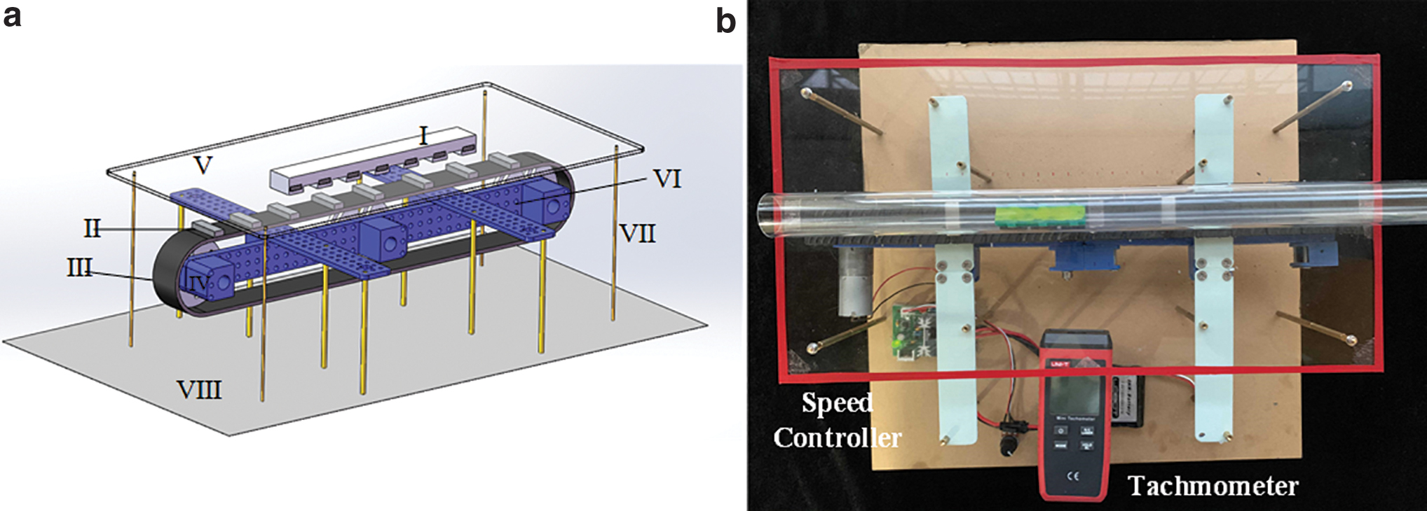
The experimental platform of the robot.
Planar discrete rod theory for the robot
Because the motion of the robot is a coupling of a large deformation, nonlinear magnetic actuation, and ground contact, the motion of the MagWorm is nontrivial to describe accurately. Thus, a simplified dynamic method is adopted. Discrete rod theory 44 is suitable for modeling slender flexible bodies like hairs or cables with contacts, as the expression of the centerline is explicit. Recently Huang et al. 45 and Goldberg et al. 46 considered the planer situation and introduced it to soft robotics. Their models for SMA actuators45,46 include experimental recordings of intrinsic quantities such as curvature and module changes. The magnetic interactions can be modeled with relative high accuracy, thus in this study the actuation terms don't rely on fitting results, providing an effective model to physically test the discrete rod theory.
In this study, a brief introduction of the planar discrete rod theory is presented with minor adjustments on expression. The model is composed of n nodes (or vertices) that are connected by n − 1 edges, seen in Figure 1b. The mass of the body has a concentrated distribution on the nodes, and the internal stresses in the edges are transformed into the concentrated nodal forces, resulting in the ordinary differential equations of the system.
A Cartesian coordinate is set, with the x-axis horizontally toward the tail direction, y-axis normal to the ground, and z-axis completing the right-handed frame. Denote
Defining the position vector of node i as
The turning angle φi between the adjacent edges
The integrated curvature κi at the i-th vertex is defined in the discrete differential geometry manner as
In the planar situation, the elastic responses include the longitudinal stretching and the lateral bending without any torsion. The internal stretching force

where E is the Young's module, Ai is the cross-sectional area, and
The internal force acting on the i-th node includes the elastic forces and the damping force
For a moving robot, we derived a form of damping force by introducing internal viscous elasticity rather than simple air drag, 44 so that the rigid body motion portion is not damped. The formula is inspired by the viscous elasticity element for absolute nodal coordinate method 47 and is presented in the Supplementary Data.
In the planar discrete rod model, the generalized coordinates are horizontal and vertical positions of the nodes:
Denote
Magnetic interactions
In this section, a seminumerical method 48 is adopted to study the interactions between cuboidal permanent magnet pairs, that is, the interaction between the drive magnet and the body magnets. The magnets are assumed to have homogenous magnetization without eddy current, and the relative permeability is unity. The dimensions of the drive magnet and the body magnet are given by 2a1 × 2b1 × 2c1 and 2a2 × 2b2 × 2c2, respectively, with a relative rotational angle θbody compared to parallel configuration (Fig. 1c). Such geometry makes it inaccurate to be simply regarded as dipoles, compared to the soft robots that use magnetic particles.19,23
A cuboidal magnet can be considered as two charged planes (upper and lower) when the magnetization direction is along its height. Given the remnant flux density
where
The closed-form expression of the field created by the drive magnet at an observing point
where the intermediate variables are
The Lorentz force and the torque acting on the center of body magnet are
where the integrations are conducted on the surfaces S2 of the body magnet. In this study, r2 is the vector pointing from the center of the body magnet toward the infinitesimal area dS2.
During simulations, two-dimensional numerical integration methods can be used to solve Equations (11) and (12). Because of the symmetry, Fmagz, Tmagx, as well as Tmagy, should be zero, which can evaluate the numerical integrations. The analytical solutions when θbody = 0 can be found in Yonnet and Allag. 40 If θbody ≠ 0, the results need to be verified through finite element analysis (FEA) software such as COMSOL®. Meanwhile, simplifications such as the unity relative permeability can be proved acceptable through FEA. It is possible to combine the magnetic field with the deformation field through the Maxwell stress tensor in COMSOL.28,36 FEA methods would require computational expensive meshing of a large air box to provide magnetic isolative boundary conditions.
Equations of motion
To impose magnetic loads onto the discrete elastic rod model, we adopt Lagrange multipliers to enforce the rigid-body (the magnets) coupling constraints. First, the generalized coordinates and the mass matrix are expanded to involve the translation and rotation of the body magnets:

where xbodyj, ybodyj, θbodyj are the horizontal and vertical position and the inclination angle of the j-th body magnet, respectively. The inertia of the body magnet includes the mass mbodyj and the moment of inertia Jbodyj.
The magnetic loads on the j-th body magnet are calculated using Equations (11) and (12), considering its relative position
The constraint equations
Ground contact has to be included in the model. The discrete rod model is effective for contact detection and reaction, because the nodal position is expressed in (xi, yi, zi)T explicitly rather than in arc length of the body. Consider the normal behavior as complete inelastic collision:
where mi denotes the nodal mass, and Δt is the time interval of the simulation. The condition yi < 0 gives a judgment when the node i is in contact with the ground. The other condition
where μs and μd are the static and dynamic friction coefficients, respectively, and vd is the transition speed beyond which the node slips and is affected by the dynamic friction. Df denotes a small sticky term, based on the observation of the sliding when the platform is inclined and the normal force is low. The external force is the resultant of the contact forces and the gravity:
Final assembly of the forces gives the equations of motion:
where
In addition, we use a constant Young's module E, assuming the extent of strains not to reach an obvious hardening effect of rubber materials. More realistic viscosity and contact models would help to further improve the accuracy.
Results and Discussion
In this section, the performance of the MagWorm is tested numerically and experimentally. The model is validated, and the mechanism of the robot is discussed based on simulation. The experiment is conducted, which tests the displacement and speed of the MagWorm embedded with different numbers of magnets. In the last subsection, the potential applications of the MagWorm are discussed and exhibited.
Model validation
Simulations are carried out with explicit integration. Before directly simulating the crawling motion, two kinds of case study are carried out to validate the model, ensuring that the magnetic couplings are imposed and the damping is functioning.
In the first case, the soft robot with three body magnets is modeled. The middle body magnet is repulsive to the drive magnet, while the two others are attractive. Note that it is representative as the elementary unit for such a robot. The remanence flux densities of the magnets are all 1.22 T in magnitude, where their signs depend on the magnetization direction. Other key parameters can be found in Table 1.
Design and Simulation Parameters
The drive magnet is lifted upward from ydrive = −52 mm to ydrive = −22 mm in 0.5 s and then fixed for 0.3 s, while keeping the drive magnet right beneath the middle body magnet. Figure 4a shows the robot postures during this procedure, while Figure 4b shows the vertical displacement of the body center and the horizontal displacements of two end points. As the drive magnet becomes closer to the robot, the deflection increases and the feet slides toward the center, and the centrosymmetry is satisfied as expected. After the drive magnet is fixed at ydrive = −22 mm, the robot tends to its equilibrium state because of the damping. This case can be used to study the equilibrium deflection of the robot body with respect to different ydrive, and ydrive = −22 mm is a suitable design for the MagWorm to obtain a biomimetic bending. At such distance, the vertical deflection reaches about 1/7 body length, which is close to Joyee's measurement of real worms 28 (about 3 mm of deflection over 20 mm of body length).

Case study for model validation.
In the second case, we consider a soft cantilever with a magnet mounted on its tip. This structure is inspired by magnetically tipped guidewires.36,37 For a large deformation cantilever bent by a tip moment Mtip from the field Bfield, there exists a theoretical solution shown in Equation (20), where mtip and θtip are the magnetic moment and the deformation angle of the tip, and L and I are length and moment of inertia of the beam, respectively. In the simulation based on discrete rod model, the beam shape (Fig. 4c) and deformation angle (Fig. 4d) both agree with the theoretical solution, and the declination in deformation when the field is weak (Fig. 4d, 3 mT) is similar to that recorded by Jeon et al.
36
This comparison proves the effectiveness and accuracy of the discrete rod model. The method is potential for modeling and control of similar slender magnetic soft robots, without the necessity of air mesh in FEA methods.
Mechanism analysis
In this subsection, simulation and experiment are both carried out to investigate the crawling details of the three-segment robot. In the simulation the drive magnet moves at 100 mm/s for 1.5 s, beginning at 50 mm ahead of the robot and maintaining ydrive = −22 mm under the robot. During experiment only one drive magnet is fixed on the cover belt, so that the robot has only one clear step forward. The experimental and numerical crawling morphology of MagWorm are presented in Figure 5a and b, respectively. The motion of the hardware robot is analyzed by the deep learning tool DeepLabCut. 51 The positions of body magnets are automatically marked and traced in the software, and the horizontal and vertical displacements during crawling motion are summarized in Figure 6a and b, together with the simulation results.

The configurations of the representative robot with three body magnets (the simulation animation can be seen in Supplementary Video S2).

The displacements during locomotion.
With the drive magnet moving backward, the wave-like body shape starts from the rear side of the robot body and travels forward, leading to a motion opposite to the direction of the drive magnet. The whole process can be roughly divided into four stages according to the positions of the drive magnet.
In stage I, the drive magnet is in front of the first body magnet. The anterior foot is lifted slightly because of the clockwise torque on the first magnet. Then the robot is anchored by the vertical attraction. In the stages II and III, the drive magnet locates at two sides of the middle body magnet. The wave is generated between the second and third body magnets, when the drive magnet is ahead of the second magnet. The reason is that at such state the second magnet has a counterclockwise torque, while the third magnet has a clockwise torque. Then the repulsive force of the center magnet results in a wave peak, lifting the robot body and dragging the anterior and posterior feet toward the center. In the end, the posterior foot is anchored by the third attractive magnet. The strong attraction creates a high-friction state, preventing the posterior foot from sliding backward when the robot body tends to recover its flat configuration. Meanwhile, the interactions on the first magnet are relatively weak, and the robot head is pushed forward to release the stored potential energy.
According to the experimental results, the robot can move forward 4.17 mm when actuated once, see Figure 6b. The second body magnet can achieve a maximum vertical deflection of ∼8.30 mm. As for the simulation, the dashed line in Figure 6a suggests that the wave peak has a maximum value of ymax = 9.07 mm, but the robot proceeds only 3.48 mm horizontally. The calculation results are consistent with the experiment for the robot's wave-like shape. The comparison is also presented by Supplementary Video S2. The posterior foot is lifted slightly in simulation, but it is not obvious in experiment.
The differences are mainly caused by the inaccurate estimate of the friction and damping. Our robot experiences surface contact and edge contact during motion (shown in Fig. 5a), and the actual rubber friction is complex to model such as the area and load dependency. 52 The horizontal friction should also bring shear effects, which are not considered in the discrete rod theory. 44 In addition, it can be seen from Equation (5) that the discrete rod theory assumes constant strain within the edges, thus the predicted deformation has lower accuracy compared to element-based methods like FEA. Except for the modeling assumptions, in experiments the drive magnet has little vertical vibration because of the reaction force from the body magnets. Thus, the hardware robot has weaker repulsive force (less vertical displacement) but stronger attractive force (larger horizontal displacement) than simulation. However, it is encouraged that the simulation can provide a sufficient reflection of the physical mechanism, which is nonintuitive to analyze considering the complex magnetic interactions.
To provide evidences for the aforementioned mechanism, some particular cases are summarized by considering specific magnetic interactions. The outcoming horizontal displacement of the third magnet is shown in Figure 6b. If there were only horizontal magnetic forces on body magnets, the displacement would not be obvious, indicating that the motion doesn't rely much on the horizontal component. It can be seen in Figure 6b that the vertical magnetic forces and the torques both contribute to the wave-like body oscillation and the forward motion. The vertical forces can create a stick-slip condition by sequentially switching the normal contact forces on the two feet, which contributes the most and resembles the motion mechanism of inchworms. At the same time, the wave-like body shape that starts at the stage II is generated by the magnetic torques. The directions of these torques are all in accordance with the desired body rotation, making the wave travel forward smoothly.
Velocity test
In living nature, there are caterpillars of all sizes. These caterpillars have different behaviors and evolve through natural selection for the best ability. Similarly, one of the influential characters of the worm-like soft robots is the body length, which for MagWorm is determined by the number of the embedded magnet patches. Figure 7a illustrates the stride length (the horizontal displacement) of the robots with three, four, and five body magnets, respectively. The displacements normalized by their body lengths are reorganized in Figure 7b. The displacements are obtained by averaging the traveled distance when a number of separated drive magnets have passed underneath.
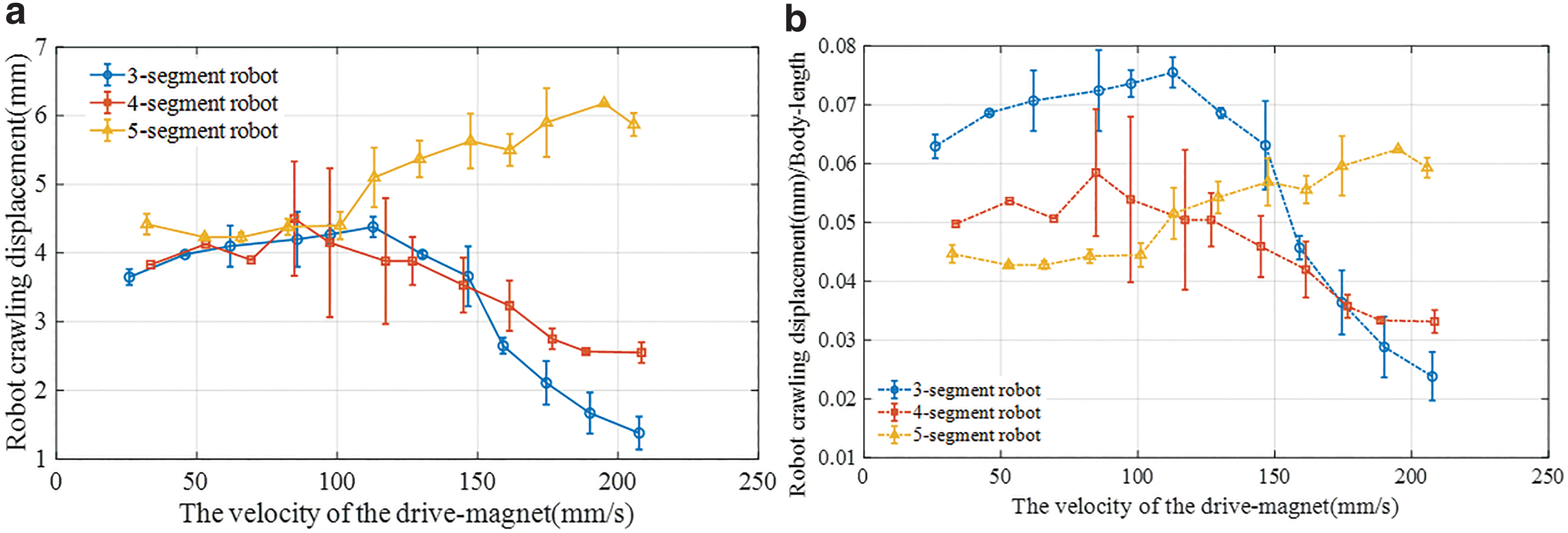
The stride length of the robots with different body lengths in the experiment, actuated once by a single drive magnet. (
These robots achieve nearly a same value of stride length when the velocity of the drive magnet vm is relatively slow (vm < 65 mm/s). The three-segment robot reaches the maximum stride over 4.3 mm when the drive magnet moves at vm = 110 mm/s. The three-segment robot and the four-segment robot both show a decreasing trend when vm is higher than 110 mm/s. The four-segment robot's repulsive magnets and attractive magnets are not centrosymmetric; consequently, there is a difference in the displacements when crawling forward and backward, and the error bars are relatively large. The displacement of five-segment robot keeps increasing until vm nearly reaches our platform's limitation (210 mm/s), because the robot has more than one attractive-repulsive-attractive unit. The phenomenon is similar to other rate-depended excitation: there exists a proper frequency for the largest response, over which the response would decrease for lacking enough time to deform.
Continuous and fast crawling can be realized by controlling the distance between the drive magnets, that is, the number of drive magnets that actuate the robot for a given time. We choose a distance of 170 mm, which is just above the longest robot body length. The highest speeds of three- and five-segment robots during experiments are 0.36 body length/s and 0.4 body length/s (38.8 mm/s), respectively. It is observed that the robots start to bounce when drive magnets move very fast. Compared with the crawling soft robots summarized by Umedachi et al., 13 the MagWorm crawls faster than those robots actuated by pneumatic technology or SMA, whose speeds are generally less than 0.1 body length/s.
Potential applications
Different design and mechanism of various worm-like robots lead to their own merits. In this section, some features and potential applications of the MagWorm will be addressed. The first topic is about the turning motion during the crawling. The feature of magnet-embedded feet of the MagWorm is similar to that proposed by Joyee et al., 28 thus these two robots can share the same strategy, which uses two permanent magnets under the anchored feet and drags the robot toward a new direction. We can also gradually misalign the drive magnet with the robot body while proceeding, see Supplementary Video S3, where we manually move the drive magnet to turn. The programmed turning strategy would require a thorough update of the current platform. In addition, the drive magnets used by Joyee are constrained to be close to the feet (0.2 mm) to reach a critical buckling load. It is advantageous for MagWorm to relax the restriction (over 20 mm) for more practical applications, since it doesn't rely on the horizontal dragging.
Inspired by scorpions* or elephant trunks, a robot with a tail-like element is fabricated to carry a load. The tail is also embedded with a magnet, which can be locked with the body magnet when the tail is folded forward. In our experiment, the robot successfully maintains crawling locomotion by carrying a load weighing about 75% of its body (Fig. 8a and Supplementary Video S4). Attached with a cotton on the head of the robot, it has the ability to clean up dispersed chippings in a pipeline (Fig. 8b and Supplementary Video S5). Figure 8c shows four snapshots of the robot with five magnets crawling in a pipe filled with water (Supplementary Video S6). Compared with the scenario walking on the ground, the behavior of the robot in the water pipe is more like undulating swimming. Even though the anchored feet might slide slightly under water, the robot is still able to overcome the water resistance and realize a smooth motion (see Underwater Crawling section, Supplementary Fig. S1). However, it should be noted that the possible applications of pipeline cleaning or inspection require that the pipe should not be ferromagnetic for the robot design. The most commonly used plastic material for household pipes is suitable, whose general thickness won't block the field requirement of the MagWorm.
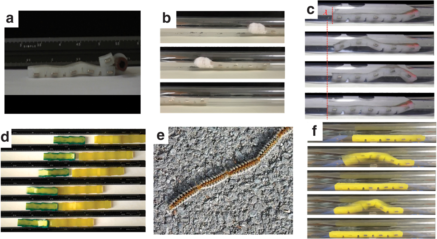
Further working patterns of the MagWorm.
When placed on one conveyer belt together, the robots with three, four, and five magnets have different speed (Fig. 7). As a result, the robots can chase each other and then link into a new longer robot (Supplementary Video S7). The screenshots of the combination process are presented in Figure 8d. This behavior of the robots is similar to caterpillars by linking together into a “train” (Fig. 8e). It makes them move through trees or on the ground while hiding heads of individual worms † . A combined longer robot with the larger supporting area is more stable. Moreover, the new robot with larger number of body magnets is still able to crawl when drive magnets move at a higher speed. It is a good mechanism for MagWorm to overcome the stall drawback of the three-segment one as shown in Figure 7. If some damages occur to the robot, the combination process may help robots cover the broken parts without leaving their runway and fixing manually. With two embedded magnets taken out, as shown in the Figure 8f (Supplementary Video S8), the five-segment robot can still move forward. Such characters of the multifeet robot help the robot maintain the crawling ability even when some damage occurs, which is significant for utilization in complex environments such as asteroid surface exploration. 53 The robot required at least three body magnets as the basic unit to achieve the crawling locomotion.
Conclusions
In this article, a new type of soft robot embedded with rigid magnetic patches is proposed. The robot differs from previous magnetic actuated designs, in that the MagWorm is: (1) a minimalistic combination of magnetic and soft parts, (2) in centimeter level, and (3) actuated by an array of permanent magnets, which creates a periodically moving magnetic field. An experiment platform is developed to generate such a magnetic field and to test the crawling performance of the robot.
The robot's interaction with the drive magnet and the deformation are modeled based on the discrete rod theory. The simulation reveals the mechanism of the wave-like body oscillation and the forward motion, which is synergistically generated by the vertical magnetic forces and torques and does not rely on the horizontal drag. The numerical crawling morphology of MagWorm is basically identical to the experimental data. Robots with three, four, and five embedded magnets are tested by adjusting the speed of the drive magnet. When the velocity of drive magnet is less than 150 mm/s, the three-segment robot has the best performance in terms of step stride actuated by a single drive magnet. When the drive magnet is at a higher speed (e.g., >150 mm/s), the five-segment robot has the best crawling performance: it can reach about 6 mm for each stride and a continuous speed of 0.4 body length/s. A rendezvous and docking characteristic is successfully demonstrated as an extension by linking two separate moving robots on the platform.
Having the advantage of being controlled by a distant magnetic field without tethers or physical contact, the MagWorm has the potential to be used for pipeline inspection and load-carrying tasks as primitively illustrated in this study. Future work will focus on its functional combining structures.
Footnotes
References
Supplementary Material
Please find the following supplemental material available below.
For Open Access articles published under a Creative Commons License, all supplemental material carries the same license as the article it is associated with.
For non-Open Access articles published, all supplemental material carries a non-exclusive license, and permission requests for re-use of supplemental material or any part of supplemental material shall be sent directly to the copyright owner as specified in the copyright notice associated with the article.