
Abstract
To create a miniature shapeshifting robot capable of controlled movement, subdivision, regeneration, passage through small channels, engulfment of particles, object manipulation, and flow manipulation, a droplet of magnetically responsive ferrofluid is used. The ferrofluidic robot can achieve the aforementioned functions when both its position and shape are controlled using a custom electromagnetic field generation system. It is demonstrated that the proposed robot can perform these functions with submillimeter and subdegree error. A robot having these capabilities can remotely perform medical and microassembly tasks requiring fine dexterity that are currently difficult or impossible.
Introduction
Medical technology is striving toward less invasive operations and procedures to benefit patients by providing shorter recovery times, decreased risk of infection, and reduced chance of complications.1–3 Furthermore, with the rapid advancement of micro- and nanofabrication technologies, the development of new microassembly processes is of great interest.
Several research groups have turned to bioinspired micro- and nanorobotics to improve medical procedures that would normally require invasive surgeries and significant operation time.1,4 These tiny robots have been developed for performing surgeries, 5 treating tumors in difficult to reach locations, 6 and delivering drugs to targeted areas. 7 However, none of these microrobots exhibit the characteristics of advanced dexterity as described above.
Onoda et al. developed an amoeba-like, self-oscillating polymeric fluid with autonomous sol–gel transition that was capable of self-motility but only through the generation of hydrostatic pressure in a capillary tube at speeds of, at a maximum, 0.35 mm/s. 8 Fusco et al. proposed flat, solid rectangular microrobots for drug delivery that can curl into a tubular shape for improved locomotion and stunted drug release and then open up again to a rectangular shape for increased drug delivery after reaching a target location. 9
Huang et al. developed a rapid prototyping method to produce microrobotic swimmers inspired by bacteria and eukaryotes utilizing synthetic flagella to achieve a broad range of motility modes in Reynolds numbers similar to those found in active blood vessels. 10 These microswimmers were made of a biocompatible hydrogel and magnetic nanoparticles and had two functions: they gave the microrobots their shape during the manufacturing process and made them move and swim when an electromagnetic field is applied. The researchers used a rotating uniform magnetic field to drive the flagella, and thus, the robot. One limitation of this design is that the robots are beholden to travel in a helical pattern determined by the shape of the flagella at creation, limiting the degrees of motion.
Fusco et al. created and tested a shape-changing robot made of hydrogel bilayers to facilitate drug delivery. 10 Their microrobot was magnetically actuated and capable of switching shape from a cylinder to a rectangular configuration under the presence of near-infrared light.
Kummer et al. invented the Octomag, an eight-coil electromagnetic field generation system, and with a magnetic microrobot with a sharp needle attachment performed untethered blood vessel puncturing of a developing chicken embryo. 5
The potential of ferrofluid droplets to be used as miniature soft robots has been explored by different research groups. Ferrofluid is a stable colloidal suspension of small ferromagnetic or paramagnetic particles dispersed in a surfactant to prevent agglomeration. The fluid properties of this material limit magnetic response to superparamagnetic behavior. That is, in the presence of an external magnetic field, the magnetic moment of the individual ferromagnetic particles in the material aligns with the magnetic field, producing an induced magnetic moment in the direction of the external magnetic field.11,12 The magnetic forces arising therefrom, in combination with the containing force of surface tension, allow for the ferrofluidic robot as a whole to be manipulated via control of the external magnetic field. This superparamagnetism property, along with its liquid properties, makes ferrofluid well suited for a range of biomedical applications.13,14
Research carried out by Komaee and Shapiro studied the movement of a ferrofluid droplet in a four-coil electromagnetic setup using a control equation based on a physical model of the magnetic and viscous forces on the ferrofluidic droplet. 15 They confirmed their model using both computational and experimental studies that demonstrated the position control; however, they did not attempt any shape control. Komaee and Shapiro, in further research with Probst et al., took the previous work an other step forward by optimizing the control of ferrofluid in a two-dimensional plane for minimal electrical power. 16
Another project by Ody et al. attempted to control the movement of ferrofluid using a combination of uniform magnetic field and hydrophilic aluminum and hydrophobic copper surfaces. 17 They could stop and “pin” a ferrofluid droplet from sliding on a surface of varying tensions. However, this method had the disadvantage of requiring a specialized surface with which to operate and could only function in one predetermined direction. Contrariwise, it has been recently demonstrated by Katsikis et al. that it is possible to control a nonmagnetic droplet in magnetic carrier fluid, having potential for microfluidics and assembly. 18 This alternative approach is, however, limited to scenarios when the carrier fluid can be chosen as the magnetically responsive part.
Moreover, there have been studies into characterization and control of the shape and deformation of ferrofluid droplets under the presence of a magnetic field. In these previous works, however, control of droplet shape has relied on augmenting the droplet surface by the addition of capillary or chemically formed membranes.
Liu et al. demonstrated a method of forming mechanically deformable ferromagnetic liquid droplets that retain some magnetization outside a magnetic field. This reversible process was based on locking the small magnetic particles of a ferrofluid in a soft, plastically deformable outer layer of the droplet. The droplets formed in this way demonstrated the capability of flow manipulation via rotation but were unable to split and recombine, or actively reshape under magnetic control only. 12
Jamin et al. investigated a method of capillary origami using a ferrofluid droplet. By using capillary membranes on the surface of the droplet, a unique shape was formed through the magnetic forces acting on the droplet-membrane assembly. 19 They discovered an instability in the shape when the magnetic field reached a critical strength that scales with the volume of ferrofluid used. This research focused on the height of the droplet/membrane assembly, this being the only metric by which shape control was identified. Furthermore, the droplet was confined to the dynamics of the origami membrane and could not change shape arbitrarily once combined with the membrane.
In another method of ferrofluid droplet shape control utilizing a membrane covered surface, Anjos et al. investigated the behavior of wrinkle and fold patterns that arose in membranes grown on ferrofluid droplets in response to applied magnetic fields. 20 Again, the existence of a membrane limited the droplet's capabilities to behave as a fluid. Furthermore, Varma et al. presented a study on the influence that a magnetic field had on the formation of ferrofluid droplets based on perimeter, aspect ratio, velocity, and inter droplet spacing in a microchannel for laboratory-on-a-chip purposes. 21 While this study did demonstrate a level of control over velocity and shape of a droplet, it did not attempt to control the direction or position of the droplet and instead allowed it to follow the flow of the carrier fluid, limiting its use.
Chen et al. investigated the formation and rotation of ferrofluid droplets under the presence of a rotating magnetic field. 22 They modeled a ferrofluid droplet as an ellipsoid and achieved ratios of major to minor axis ranging from 1.5 to 3.5. However, they did not attempt to simultaneously control position and shape of the droplet and thus could not have achieved advanced dexterity.
Modeling techniques for ferrofluid droplet shape in circumstances mirroring similar applications have also been investigated. The behavior of a ferrofluid droplet subjects to both shear hydrodynamic flow of a carrier fluid and magnetic forces due to an applied field has been explored by Cunha et al., vital for medical applications involving dynamically flowing carrier fluids. 23 Zhu et al. reported experimental and numerical results for how a droplet of ferrofluid deforms under a uniform magnetic field. They studied the profile of the droplet on a superhydrophobic surface and then developed a three-dimensional (3D) numerical model to predict the deformation under different magnetic fields. 24 This research examined an immobile droplet and made no attempt to control it.
Ghaffari et al. created a computational fluid dynamics (CFD) model of a falling ferrofluid droplet 25 and confirmed it with experimental data from Afkhami et al. 26 They later expanded upon their previous work and added collisions to their model 27 using the experimental data from Qian and Law. 28 The work of Ghaffari et al. aligned well with the experimental data presented. Observation-based modeling of ferrofluid droplets is progressing, although applied control on the shape of the droplet has yet to be achieved and may be needlessly complex. Despite all the efforts in this field and among all studies on ferrofluid droplets, none has sought to combine both shape and position control into one unified control scheme capable of manipulating the droplet with a high level of dexterity, which considerably limits the possible applications.
Objectives
For a small-scale liquid robot to assist with minimally invasive medical procedures and new microassembly processes, advanced dexterity—characterized by controlled mobility, deformation, splitting, recombination, squeezing through narrow gaps, engulfment or pushing of objects, and induction of local flow—is highly desirable.
Considering the potential of ferrofluid droplets as small-scale soft robots to enable higher dexterity, we propose a miniature, deformable ferrofluidic robot, capable of controlled translation and shape change that can achieve the aforementioned maneuvers.
The achievement of these functional maneuvers via the present research is conceptualized in Figure 1. Using a droplet of ferrofluid, all these functions can be performed by carefully controlling the external magnetic field generated by the electromagnetic coil system, as shown in Supplementary Figure S1. In particular, we present the approach to control both position and shape of the ferrofluid droplet using either four or eight electromagnetic coils. Since the position control of ferrofluid droplets using external magnetic fields has been well studied, we focus on shape control and combined shape and position control of ferrofluidic droplets. Finally, by employing these functionalities, we demonstrate capabilities such as sorting particles and flow generation for microfluidic and lab-on-a-chip applications.

Conceptualization of the ferrofluidic robot. Electromagnetic coils generate controlled magnetic fields to produce five functional maneuvers:
Materials and Methods
The experimental setup
An electromagnetic field generation system is used to produce and manipulate the actuating magnetic field. 5 Eight stationary current controlled electromagnetic coils are used in the setup (Supplementary Fig. S1): four arranged in-plane horizontally, equiangular around the workspace and facing inward, and the remaining four coils staggered 45° both around the workspace and up toward the top of the workspace, with each coil facing downward at a 45° angle toward the workspace. Each coil is composed of a solid iron core and 712 wraps of 14 gauge copper wire in 6 layers. The system is calibrated to 27 points comprising 8 “octants” within a 32 × 32 × 35 mm3 workspace cube. This calibration accounts for the linear relationships between each coil's magnetic field intensity and the robot's physical positioning in the workspace, thus allowing each coil to affect the robot predictably regardless of the robot's location.
Two power supplies are used: a TITAN F1208 capable of providing 60 A and up to 1200 W of electrical power, and an eFueld PSU50A V2 capable of providing 50 A and up to 1200 W of electrical power. Four Sabertooth 2X25 dual motor drivers are used as amplifiers between the power supplies and the coils. Amplifiers are connected to a Sensoray Multifunction analog/digital I/O—Model 826 data acquisition card (DAQ) to receive the controlling inputs. To avoid the adverse impacts of fluctuating temperatures on the magnetic field generation capabilities of the electromagnetic coils, a Fluid Chillers, Inc. NEMA 4X Outdoor Enclosure cooling system circulates chilled water through copper tubing that is wound around each coil. While running this cooling setup, system temperatures remain between 21°C and 24°C.
The workspace is composed of an open-top cube assembled from matte finished white acrylic square tiles, laser cut for repeatability and assembled via superglue, and a 3D printed white polylactic acid (PLA) fixture that holds the cube in place and acts as a sliding handle for inserting the cube into the center of the electromagnetic coil system. The cube is filled with 30 mL of 70% isopropyl alcohol, and then, 5 μL of the ferrofluid is added via micropipette, forming a droplet.
In this study, only one ferrofluid (EFH-1) is explored. However, other ferrofluids will likely behave similarly as they all are colloidal suspensions of magnetic particles, regardless of particle size and suspension fluid. There are many types of ferrofluid with different properties, some of which are biocompatible. EFH-1 ferrofluid is chosen for this study since it is found immiscible in 70% isopropyl alcohol, a commonly available substance.
The scalability of ferrofluid droplet size is dependent on the competing forces acting on it. The surface tension and cohesive forces work to bring the droplet into a spherical shape while magnetic forces attempt to deform it. The surface tension forces act on the surface while magnetic forces are body forces. Thus, the bigger the droplet gets (centimeter scale), the smaller the surface tension becomes compared with the magnetic forces, which makes it difficult to keep the droplet together while applying magnetic forces. However, the surface tension becomes dominant in smaller droplets (microscale), which forces the droplet into a spherical shape.
One stationary camera provides visual feedback of the workspace from the top. The camera is programmed to capture frames of 276 × 280 pixels, of which the ferrofluid's range of motion spans a 240 × 240 pixel region. Resolution is reduced to increase frame rate by reducing image processing computation time. The entire system is controlled through C++ by a single Dell Precision T1700 computer.
Control of the robot's position and shape
One approach for controlling the position and shape of the ferrofluidic robot is to find a dynamic model of the droplet interacting with the environment as well as the magnetic fields and design a model-based controller for it. This model would be required to capture complex dynamics usually described by a set of partial differential equations, which in most cases may not be solved analytically.24,29 Even for the cases that the analytical solution could be obtained, it is still required to solve the inverse problem to find the required currents of the coils for every desired position and shape of the robot. Furthermore, physical terms found in such a model need to be observed or estimated for each control loop iteration.
To bypass the unnecessary complexity, computational cost, and time delay issues, a model-free controller is designed to control the position and shape of the robot. This controller has to withstand disturbances and uncertainties and requires feedback information. Here, visual feedback is used to get the real-time information of the robot. By processing the feedback images, information about the position and shape of the robot is computed and provided to the controller.
The first step in defining the control problem is to standardize the robot's shape definition. If we do not apply abrupt changes to the resultant magnetic field, to a very good approximation, the robot can be modeled as an ellipsoid.22,30 The projection of this ellipsoid onto a plane crossing its center parallel to the horizon is an ellipse in 2D, which can be easily seen from the camera installed above the workspace. This ellipse and its corresponding parameters are used to characterize the position and shape of the robot.
It is worthy to note that the robot shape in 2D is determined using two parameters: the length of the ellipse major axis radius, L (stretch length), and its orientation,
The electromagnetic field generation system can be used for controlling the above-mentioned four variables through a multi-input multi-output controller.
The proposed architecture for the controller is composed of three proportional integral derivative (PID) controllers: a controller on position composed of two identical PID controllers manipulating magnetic field gradient to control the droplet position, a PID controller on the magnetic field direction to control the ferrofluid droplet's stretch direction, and finally, a PID controller on the magnitude of the magnetic field to control the ferrofluid droplet's stretch length. These controllers are all closed loop, relying on visual feedback to maintain control.
The feedback loop uses the captured images of the workspace to compute four variables: Px, Py, L, and
To control the position of the robot, the position error vector,
The electromagnetic field generation setup is designed with the intention that the magnetic field generated by each coil is in the linear regimen over the entire workspace. Due to the relative sizes of the electromagnetic coils and the workspace, the magnetic field lines for each coil are nearly parallel to its axis. However, a thorough calibration process in which the field and gradient contributions of each coil at different current values are tabulated is necessary to accurately calculate the required currents. The force needed to act on the robot to move it toward the desired position can be written as:
where
While the robot does not move under zero resultant force, it can be stretched proportional to and in the direction of, the magnetic field vector. In particular, magnitude, LB, and angle,
Therefore, to control the shape of the robot, the angle and intensity of the magnetic field are defined in terms of the errors in stretch angle,
where
As with all controllers, the response of the system can be tuned to fit a desired behavior by altering these gains. The gains presented in this study were tuned specifically for the experiments. It is known that ferrofluid gets stretched along its magnetization vector, which is always aligned with the external magnetic field. By applying control on the magnetic field direction, the stretch angle and magnitude can be controlled.
Magnetic field direction can be used to define the desired stretch angle. The magnetization of the ferrofluid is proportional to the external magnetic field acting on the ferrofluid. The applied magnetic gradient and the magnetization of the ferrofluid determine the force applied on the ferrofluid.
The electrical current in each coil to generate the required magnetic field and gradient can be determined considering the linear relation of magnetic field and electrical current. The net magnetic flux density and gradient can be calculated using the linear superposition of each electromagnetic coil's magnetic flux density and gradient contribution. As eluded to earlier, the contribution of each coil is measured through a calibration process for 1 A current.
The required current (

where
For this application, the magnetization vector
Control scheme
To control the position and shape of the ferrofluid on a predetermined trajectory, the desired path and evolution are segmented into a series of steps, which include a point-to-point breakdown of the desired path, required stretch angles, and required stretch lengths, and fed to the controller in the form of an array. Each row in the array has four components corresponding to the x position, y position, stretch angle, and stretch length of the next desired pose. The magnetic field and gradient are controlled by PID controllers to steer the ferrofluid toward the next comprehensive pose in the array. As the droplet approaches the desired configuration, and falls within a predefined threshold of accuracy for each of the four metrics, the controller will move on to the next point in the path, methodically moving through each predefined position/shape path.
Feedback parameter acquisition
The camera collects one top-view image of the workspace during every iteration of the experiment loop. The ferrofluidic robot appears black against a white background, making it very easy to threshold the image into a binary format. This thresholding process results in a binary image: an array of Booleans marking only the pixels hosting the ferrofluidic robot. From this binary image, the center point of the droplet is obtained by the moments method in the OpenCV image processing library for C++. This method finds the “centroid” of the image by taking a weighted average of the pixel values in the x and y directions and dividing by the area of nonzero pixels. This method is effective for binary images, in particular.
The droplet's contours are determined from the binary image using the Canny method in OpenCV for C++. The Canny method is based on an edge detection algorithm invented in 1987 by John F. Canny and is a built-in function of the OpenCV library. 31 The contours are an array of Cartesian pixel coordinates that describe the outer boundary of the droplet. If multiple contours are detected in the image, all contours are combined into a single array and duplicate pixels in that resulting array are removed.
This final array of pixels is used to determine the shape information by the following approach: The stretch angle,

Results and Discussion
To evaluate the performance of the control architecture, shape controller is verified in isolation and then coupled with position controller for verification in a combined experiment. The shape control and combined position and shape control experiments quantify the capabilities of the robot's control scheme and actuation system. Quantified results of these validation experiments precede subjective demonstrations of five functions: splitting and recombination, squeezing through small passages, engulfment of particles, pushing particles, and flow generation. These experiments on various functional maneuvers are presented as extensions of the control strategy. The goal of these experiments is to demonstrate complex maneuvers of interest that are made possible through the combination of the shape and position control scheme.
Shape control
A key feature of our approach is the ability to control the shape of the ferrofluidic robot, defined by two parameters: the major axis radius of an ellipse imposed on the robot's silhouette, L (stretch length, mm), and the angle between that ellipse's major axis and the horizontal axis,
Shape control experiments demonstrate performance of the robot's stretch length and stretch angle control, as presented in Figure 3. Figure 3A plots the steady-state performance of stretch angle control, showing mean experimental angle ±1 standard error and the specified angle in the case of utilizing only four coils. Figure 3B plots the same for the case of control using eight coils. The results are notably similar. Average and maximum error over all steady-state angle measurements during this experiment is 0.7° and 5.8°, respectively, in the case of four-coil control, and 0.1° and 5.9°, respectively, in the case of eight-coil control. Images of the robot are included in the figure to visualize stretch angle control.

Shape control. Stretch angle (
Stretch length control capabilities are plotted in Figure 3C for seven different specified stretch length radii ranging from 1.7 to 4.4 mm. Experimental steady-state mean stretch length ±1 standard error is plotted under the specified stretch length. The mean stretch length is calculated by taking the average of the stretch length over 100 frames during the experiment after the angle has settled. Average and maximum error over all steady-state mean stretch length measurements is less than 0.1 mm, which is the minimum resolution that can be measured with this setup, for both four- and eight-coil control methods. Robot images visualize relative stretch length and are not to scale with respect to any axis. The robot shape can be controlled at any position in the workspace, and to any stretch intensity up to the robotic droplet splitting.
The shape of a ferrofluid droplet is indeed enforced by the stresses acting on its boundary. Considering an inviscid, isothermal, and incompressible ferrofluid droplet surrounded by a nonmagnetic fluid, the balance of stresses at the boundary between the ferrofluid droplet and the surrounding fluid can be expressed using Equation (5) (Fig. 4)24,32:

Balance of normal stresses at the interface of ferrofluid droplet and the surrounding fluid.
In this equation, composite pressure (
In Equation (5), the magnetic surface force density (
Since the surface tension of the ferrofluid in small magnetic fields can be considered constant, 33 the curvature of the boundary is the only factor responsible for changing the capillary pressure. Thus, by increasing the magnetic field strength, the curvature of the droplet boundary will change to balance the interfacial stresses. As changes in the magnetic surface force density are more significant at the points where the magnetization vector is normal to the boundary (along the magnetic field), the curvatures at those points experience larger variations. Hence, according to Supplementary Equation (12), the largest stretch occurs in the direction of the magnetic field (Supplementary Fig. S2). In short, as the magnetic field strength increases, the droplet stretches along the direction of the magnetic field to balance the increased magnetic surface force density.
Combined shape and position control
Position, stretch angle, and stretch length of the ferrofluid can be independently controlled by the magnetic field gradient, direction, and magnitude, respectively. Three independent PID controllers are used to control the ferrofluid droplet [Eqs. (1) and (2)], and as a result, any combination of the position and shape can be achieved.
To demonstrate the ability to simultaneously control both position and shape, an experiment is performed in which the robot is tasked with following a specified path while holding specified stretch angles and lengths in four intervals. Results of this experiment are presented in Figure 5, where mean experimental path ±1 standard error and specified path are plotted together. The robot follows the lemniscate path twice over the course of one experimental trial, and as such the figure is split into two parts for clarity. Figure 5A displays the mean experimental path ±1 standard error of the first half of the experiment, where the robot is set to a horizontal stretch angle and then to switch from one stretch length to a second stretch length after completing the first half of the lemniscate.

Combined position and shape control when following a lemniscate path. The lemniscate path is followed twice per experimental run: first holding a horizontal
Likewise, Figure 5B displays part two of the experiment where the robot is set to hold a vertical path and switch from a first stretch length to a second stretch length after completing the first half of the lemnsicate path. For these experiments, the position, the stretch angle, and the stretch length are controlled in closed loop. Data for this figure are taken over five experimental trials. Images of the ferrofluidic robot are underlaid beneath the plot to show the stretch angle and length changes over the course of the experiment. The average and maximum error of the experimental mean from the specified path for this experiment is 0.2 and 0.7 mm, respectively, for the four-coil case, and 0.2 and 0.6 mm, respectively, for the eight-coil case.
Probst et al. performed position control of a ferrofluid droplet utilizing a four-coil setup and achieved errors ranging from 0.28 to 4.7 mm, for experiments with different-sized droplets following straight, square, and spiral paths. 16 From the same research group, Komaee and Shapiro performed a similar position experiment with simulation, where deviations from the desired path are reported visually. 15 The errors in position during path-following achieved in both studies are comparable with those achieved in the present study.
Although the eight-coil control is singularity-free, the four-coil control suffers from singularity when the stretch angle is 45° (aligned with two coils). In this case, if the stretch angle needs to be maintained, the position control is only feasible along the major axis of the droplet (i.e., along the axis of the two coils the droplet is aligned with).
As shown in Figure 3, there are consistent deviations from the path. It may be due to the momentum that the droplet picks up as it accelerates during certain parts of the path. As velocity is not controlled, the actual velocity of the droplet may result in the droplet overshooting the desired point, between controller iterations. Increasing the control frequency would mitigate this issue. However, control frequency and resolution of the image for visual feedback are competing parameters: to increase the control frequency, the image resolution would need to be reduced, and vice versa. Coupled improvement of image resolution and control frequency could be achieved by improving the computational power of the system used to run the control program.
Functional maneuvers
As mentioned in the Introduction section, other researchers have used electromagnetic coil systems to manipulate either the position or the rotation and stretching of a ferrofluid droplet. However, none have manipulated a ferrofluid droplet's path while simultaneously controlling its shape.
Utilizing the position and shape control capabilities quantified above, the robot is capable of performing complex motions and functional maneuvers, namely: subdivision, regeneration, particle engulfment, particle sorting, and flow induction. Each maneuver is defined in terms of the robot's position, stretch length, and stretch angle, and performed in closed-loop control. Successful performance of such tasks is demonstrated and visualized in Figure 6 and in Supplementary Video S1. All these experiments are performed using only four coils.
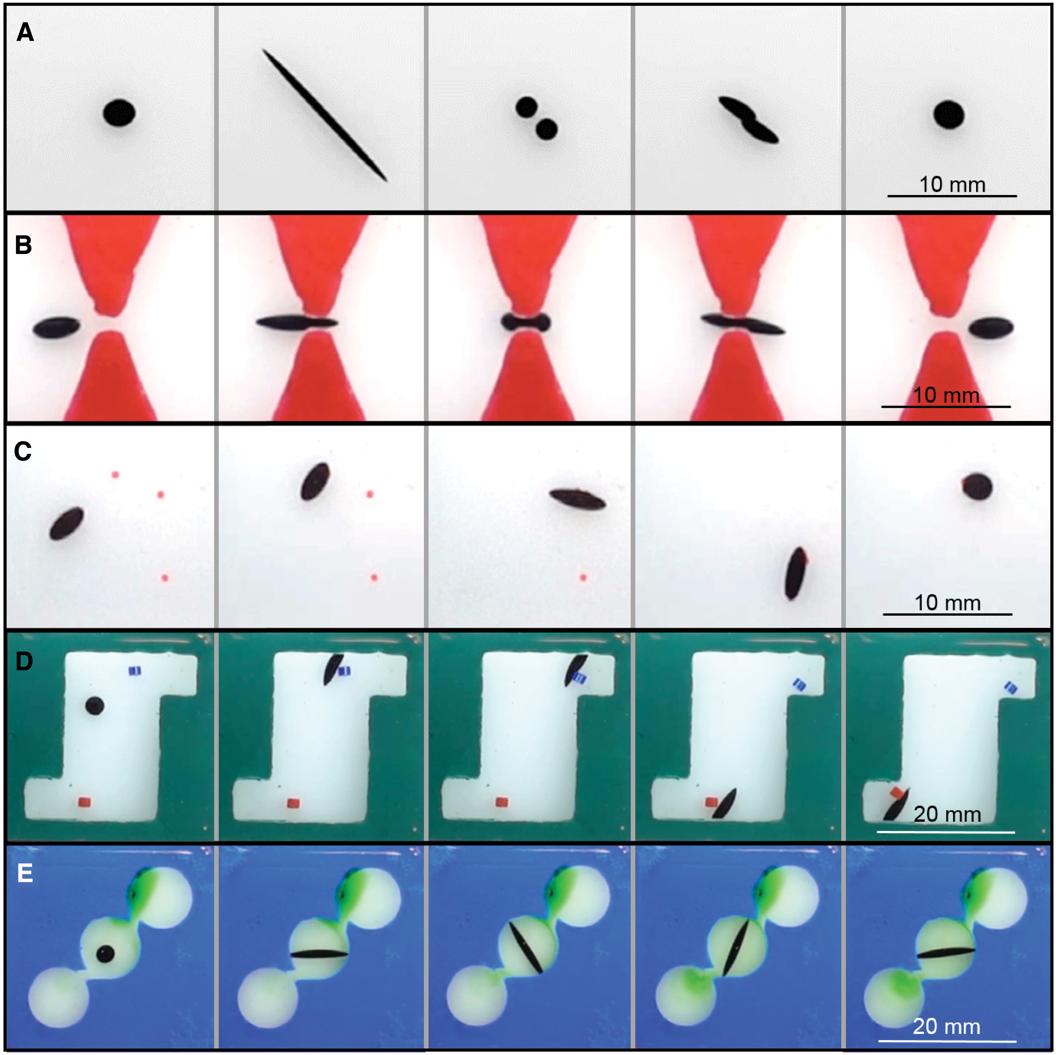
Functional maneuvers.
Figure 6A demonstrates the robot's ability to split itself into separate parts and then recombine. The shape control scheme is applied to produce a short pulse at a specified stretch angle
The robot's ability to squeeze through a narrow channel is shown in Figure 6B. To accomplish this task, the closed-loop position control scheme is used to move the robot to the channel entrance, and then, a directed pulsing motion is induced by combining the position control scheme with automated pulsing shape control signals. This pulsing action allows the robot to make incremental progress as it squeezes itself through the channel. The channel opening is 1 mm at its narrowest point. The robot can also be moved through a narrow channel by increasing the stretch length without pulsing shape control; however, depending on the channel width, it may result in splitting due to a large aspect ratio and the resisting forces applied by the channel edges.
As is demonstrated in the image sequence in Figure 6C, the robot can successfully “hunt” and engulf wettable colored particles. When the ferrofluid droplet used in this study is submerged in isopropyl alcohol, glass and polished acrylic are considered as nonwettable, whereas polyethylene and most other plastics are wettable materials. The colored particles used in this experiment are wettable polymer beads (Cospheric Innovations UVPMS-BR-1.20 Fluorescent Red Polyethylene Microspheres) placed in the workspace randomly. The positions of the particles are obtained optically at the beginning of the experiment.
This demonstration utilizes a combination of the position control scheme described earlier and a colored particle detection and tracking subprogram. The robot follows a path in closed loop, which sequentially passes through the colored particles in a chosen order. The robot carries the engulfed particles as it continues along its path to engulf subsequent particles. This effectively accomplishes clearing the workspace and transporting the particles to the robot's end location. It is, however, observed that the robot becomes less responsive to the actuating magnetic field after gathering multiple particles. This may be due to the ferrofluid carrying extra weight that does not contribute to its magnetic properties. It is important to note that this functional maneuver is only achievable with particles that are wettable by the ferrofluid.
In Figure 6D, the robot is shown completing a task in which it must push two colored particles into separate target areas. This demonstration utilizes position-only control to place the robot to the side of the particle in preparation to push and then uses a combination of shape and position control to push the particle into the target zone. The particles are colored glass cylinders of 1.3 mm diameter and 1.6 height. Glass is chosen as it is not wettable by the ferrofluid in 70% isopropyl alcohol. In addition, cylindrical particles are chosen for ease of pushing due to reduced friction through rolling. It is important to note that, in contrast to the engulfment maneuver, manipulation and sorting are only achievable for particles that are not wettable by the ferrofluid.
As shown in Figure 6E, flow can be induced in a microfluidic channel by controlling the robot's shape. This experiment utilizes closed-loop shape control only, maintaining stretch length and manipulating stretch angle incrementally to produce a rotary pump-like mechanism. The microfluidic pump in Figure 6E is designed with three chambers: one to hold colored dye to visualize flow (top), one to contain the robot (mid), and the last containing only the carrier fluid to qualify flow (bottom). Two channels connect the three cells and are designed as nozzles/diffusers oriented to bias flow in the desired direction. The channel designs are based on a microfluidic pulse pump designed by Kawun et al. 34 The channels are also oriented to take advantage of the robot's rotation. A schematic of the rotational pump design is presented in Supplementary Figure S3.
Conclusion
Using an electromagnetic coil system, a control scheme is adapted for actuating a ferrofluid droplet robot in simultaneous position and shape control. The system uses visual feedback with closed-loop control on position in x and y, stretch length, and stretch angle. Precision in the shape control and combined shape and position control of under 1 mm was demonstrated for all experiments. Five functional maneuvers are presented to illustrate the potential utility of the robot's advanced dexterity. The presented combination of actuation and control of a ferrofluid droplet robot is thus presented as a system for further research, with potential application in medical and microassembly processes.
In general, rigid robots may present higher accuracy in position and orientation control compared with ferrofluidic robots or other types of soft robots. However, some of the interesting functionalities offered by such soft robots (e.g., splitting, recombination, squeezing through narrow gaps, and particle engulfment) may not be readily achieved by their rigid counterparts. Achieving such dexterous functionalities are the main motivation behind this study, but additional efforts need to be made to further improve the accuracy and precision in control of the proposed ferrofluidic robot.
Additionally, many other exciting possibilities remain to be investigated. Control of position and shape in three dimensions is the logical next step following this research and would enhance the effectiveness and adaptability of the robot in potential applications. Furthermore, a system and control scheme capable of controlling the shape and position of multiple robots independently would also be of great interest and thus another potential direction for future research.
Footnotes
Acknowledgments
The authors would like to acknowledge Michael Kintscher for helping with development of the magnetic coil system, Edward Faillace for contributing to some of the experiments, Kenro Kusumi, Rebecca Fisher, and Spring Berman for fruitful discussions about bioinspired ferrofluidic robots, Paolo Velcich for permission to use a CAD camera model asset for creation of the ![]() , and Arizona State University for financial support.
, and Arizona State University for financial support.
Author Disclosure Statement
No competing financial interests exist.
Funding Information
No funding was received.
References
Supplementary Material
Please find the following supplemental material available below.
For Open Access articles published under a Creative Commons License, all supplemental material carries the same license as the article it is associated with.
For non-Open Access articles published, all supplemental material carries a non-exclusive license, and permission requests for re-use of supplemental material or any part of supplemental material shall be sent directly to the copyright owner as specified in the copyright notice associated with the article.