




Abstract
This study presents the design and test of a novel self-adaptive soft gripper, integrating pneumatic actuators and bistable carbon-fiber reinforced polymer laminates. The morphology was designed using the distinct structural characteristics of bistable structures; and the stable gripping configuration of the gripper was maintained through the bistability without continuous pressure application. The sufficient compliance of bistable structures makes the gripper versatile and adaptable to gripping deformable objects. First, a pneumatic-actuated method was introduced to achieve the reversible shape transition of the bistable structure. Next, three arrangement methods for actuators were analyzed with respect to the bistable transition and curvature, where it was found that the cross-arrangement is optimal. The effects of pneumatic actuators with different geometrical parameters on the response times are discussed, and the results show that the bistable structure can achieve shape transition within milliseconds under low pressure. Furthermore, the numerical and experimental results show good agreement between critical pressures and out-of-plane deformation. Furthermore, the shape retention function of the soft gripper was studied by using it to grasp objects of various sizes even when the pressure was reduced to the initial state. The bistable laminates exhibit sufficient compliance, and the deformed laminates can automatically accommodate the deformation of objects. The relationship between the weight and size of available gripping objects was studied; functional tests confirmed that the proposed soft gripper is versatile and adaptable for gripping objects of various shapes, sizes, and weights. This gripper has immense potential to reduce energy consumption in vacuum environments such as underwater and space.
Introduction
Soft robotics has emerged as one of the fastest growing fields in the robotics community. The increased attention it is receiving among academia indicates its potential to revolutionize the role of robotics in society and industry. 1
Soft robotic grippers based on pneumatic actuators2,3 have been studied actively because they have a simple morphological structure and offer flexible bending motion. Soft actuators with pneumatic actuation exhibit good potential for various applications owing to their characteristics, including flexibility, high-speed large bending, and their ability to deform to manipulate delicate objects.4,5
Mosadegh et al. 6 described a new design for pneu-nets that reduces the amount of gas needed for their inflation, thereby increasing the actuation speed. A simple actuator can bend from a linear to a quasicircular shape in 50 ms when pressurized at ΔP = 345 kPa. Tolley et al. 7 modified the capability of pneu-net actuators to operate at elevated pressures (up to 138 kPa); these can actuate the legs of the robot and hold payloads of up to 8 kg. Zhu et al. 8 proposed a gripper which contains two identical soft fingers, including pneumatic actuators and an integrated layer-jamming unit that can freely deform at low stiffness, while maintaining its robust grasping ability at high stiffness during high levels of acceleration. Li et al. 9 designed bionic winding structures that are driven by pneumatic artificial muscles having a high load capacity and are capable of gripping various objects. Fei et al. 10 proposed a gripper that can grip objects of size 0–245 mm and orientation −88.2° to 90.8° (pitch/roll); its maximum gripping force was 40 N, with a response time of 1.22–1.60 s to force and 0.56–2.61 s to motion.
Furthermore, to achieve more animal-like movements in a soft robotic gripper, researchers have recently combined granular jamming, 11 spring actuators, 12 and shape memory alloy-based actuators 13 to control the stiffness and enable shape retention. Although this addresses the need for a continuous air pressure to maintain shape, heating equipment is required to heat the shape memory alloy to induce phase transition to bend the pneumatic actuator when necessary.
In this study, we fabricated a soft pneumatic gripper integrated with bistable structures to maintain the shape of the gripper when gripping objects, while simultaneously reducing the energy consumption effectively. Bistable structures—a class of highly geometrically nonlinear morphing structures—have two stable configurations, in which their respective positions can be retained without the continuous application of an external force.14–21 The soft pneumatic gripper exploits these distinct structural characteristics actuated by pneumatic actuation; thus, the shape of the bent gripper is maintained by bistability.
Concurrently, the integration of a bistable structure and pneumatic actuator has been considered to realize snap-through and snap-back motions and smart actuations for bistable carbon-fiber reinforced polymer (CFRP) structures in existing reports, including shape memory alloy actuation,22–25 electroactive polymer actuation,26,27 piezoelectric actuation,28–30 thermal actuation,31,32 and magnetic actuation.33–36 However, shape memory polymer actuation requires an environment with variable temperatures to change shape so that it may respond slowly. For electroactive polymer actuation and piezoelectric actuation, extremely high voltage is required to achieve the transition. Thermal actuation, conversely, can deform bistable laminates with lower power and requires a high temperature for the heating plate. Although magnetic actuation can achieve a noncontact drive, the magnetic field is difficult to control.
For the other driving methods, several researchers have reported methods to flexibly control the deformation of the bistable structure. Li and Wang 37 presented a fluidic origami that can switch between being monostable, bistable, and multistable with pressure control and can provide a rapid “snap-through” type of shape change mimicking that in plants. Fan et al. 38 presented a new paradigm for designing responsive hydrogel sheets that can convert prestored energy and cause rapid reverse snapping (<1 s) to release the energy. Lee et al. 39 realized swelling-induced snap-buckling in a three-dimensional (3D) microhydrogel device, inspired by the insect-trapping action of the Venus flytrap. In addition, a simple design strategy for the rapid fabrication of prestressed soft actuators (PSAs) was presented by Pal et al. 40 ; the elastic energy that PSAs store in their prestressed elastomeric layer enables the fabrication of grippers capable of performing with zero power requirements.
Furthermore, in our previous research, 41 we designed a multistage pneumatic actuator for a multistable carbon fiber-reinforced structure to achieve snap-through rapidly. Thus, soft pneumatic actuation with appropriate arrangement is considered as a feasible driving method to trigger the snap-through and snap-back shape transitions flexibly.
This work proposes a novel self-adaptive soft gripper with the purpose of shape retention that comprises two bistable laminates exhibiting reversible shape transitions actuated by pneumatic actuators. The report is organized as follows. In Design and Methods, the manufacturing processes of pneumatic actuators and bistable CFRP laminates are presented, and basic information on the bistable CFRP laminates is presented to clarify the bistability actuated by pneumatic actuation. Numerical Simulation describes the finite element (FE) modeling carried out to investigate the morphology and trigger force of the bistable laminates with pneumatic actuators. In Results and Discussion, three arrangements of actuators are discussed to determine the optimal driving strategy.
Furthermore, the experiment on the shape transition and loading test for the bistable laminates by pneumatic actuation is described, including the out-of-plane deformation of the two stable configurations. The experimental results are compared with those of a numerical simulation obtained using the finite element method (FEM) and are observed to be in good agreement. Finally, a soft gripper with a bistable structure is proposed and designed. Testing was conducted and yielded the following: (1) a dynamic response of the gripper at the millisecond level; (2) the gripping objects exhibited satisfactory shape retention even when the pressure was reduced to the initial state; and (3) the deformed laminates exhibited sufficient compliance and self-adaption to automatically conform to the deformation of objects.
Design and Methods
Pneumatic actuator design
In the study design, a pneumatic actuator was expected to actuate the shape transition of a bistable structure under low air pressure. Hence, the design goal of the pneumatic actuator was to produce a large force under a specific input of air pressure. Based on existing literature, 42 the radius of the pneumatic actuator has a great impact on its output force. However, infinitely increasing the radius will undoubtedly increase the mass of the structure, resulting in higher gravity. When the pneumatic actuator adheres to the bistable structure, gravity will affect the curvature of the overall structure. Accordingly, to facilitate the attachment of the pneumatic actuator to the bistable structure and the winding of the radial limit line, we designed the pneumatic actuator in a semicircular shape. The section structure is continuously used for the air chamber of pneumatic actuators (verified in our previous research results) to successfully actuate the snap-through process of a multistable structure. 41 Furthermore, the length of the pneumatic actuator is designed to be similar to that of the bistable structure.
To explore the influence of pneumatic actuators with different geometric sizes on the driving effect, three kinds of pneumatic actuators with different geometric parameters were designed and fabricated, as shown in Figure 1a and Table 1. R denotes the radius of the pneumatic actuator, r1 and r2 denote the radii of the chambers, S is the section area of the chamber in different pneumatic actuators, and h represents the distance between the center of the chamber and the lower surface of the pneumatic actuators.

Soft pneumatic actuators.
Geometric Parameters of Three Kinds of Pneumatic Actuator
Figure 1b–e shows the design and the fabrication strategy used to generate the components and structure of the soft pneumatic actuator. The pneumatic actuator was made of commercial silicone rubber (E615; Shenzhen HongYeJie Technology Co. Ltd.). Molds with topographic features were designed using SolidWorks (SolidWorks, Corp., Waltham, MA) and were fabricated by rapid prototyping technology, specifically, industrial 3D printing using resin, with advanced Low Force Stereolithography technology (Form 3; Formlabs).
The E615 type silicone rubber used in the experiment is a two-component silicone rubber, so the two components, including (part A and part B), need to be blended together in a certain proportion to cure. First, as shown in Figure 1b, part A and part B of the silicone rubber solution were mixed in a ratio of 1:1 and stirred with a glass rod for 5 min to mix well. The uncured silicone rubber was then placed in a vacuum drying oven for 10 min to remove the air bubbles. Next, two molds initially coated with Vaseline for expedited demolding were assembled, and the uncured silicone rubber was poured into the molds.
To prevent the silicone rubber from generating bubbles during pouring into the molds, it is necessary to remove the bubbles in the vacuum drying oven again. Subsequently, as shown in Figure 1c, small sticks with the same cross-sectional shape as the air chamber shape, which was made of aluminum, were inserted into the molds; these thin sticks precisely occupied the space within the silicone rubber to form air channels. Finally, a positioning end cover was placed on each mold to fix the position of the small stick to prevent the position of the small rod from tilting, thereby forming an accurate air channel. Although silicone rubber can be cured at room temperature, to reduce the time required for curing, the temperature in the vacuum drying oven was then increased to 45°C for 2 h to cure the silicone rubber.
The silicone rubber body was demolded after curing, and radial-limiting wire with a diameter of 0.3 mm was wound around the outside of silicone rubber body at intervals of 5 mm, as shown in Figure 1d. Next, 441 organic silicone (Ausbond Co., Ltd.) was applied evenly along the radial-limiting wire to allow it to adhere to the surface of the silicone rubber body, to prevent the wire from sliding after repeated use of the pneumatic actuator. Meanwhile, the sealing end covers fabricated by 3D printing with resin and gas tubes were installed on both ends of the silicone rubber body using 441 organic silicone to prepare the soft pneumatic actuator, as shown in Figure 1e.
When the central chambers are inflated with compressed air, the air pressure acts on the inner surface of the silicone rubber body and the end face of the sealing end cover so that the silicone rubber body is subjected to radial and axial forces. The silicone rubber body overcomes its own elasticity; the radial expansion and axial elongation are shaped under the action of these forces. The radial-limiting wire constrains the radial force to prevent the radial expansion of the silicone rubber body, while providing a certain axial displacement compensation; the silicone rubber body can therefore only perform the motion of axial elongation.
Pneumatically actuated bistable laminates
Owing to the directionality of CFRP ply, 43 CFRP laminates can form a bistable structure with lay-ups (0°/90°); here, these were manufactured using autoclave techniques within a vacuum bag. The T700/Epoxy prepreg with 30% resin content was used as a CFRP, for which the mechanical properties are listed in Table 2. Bistable laminates with a lay-up design were fabricated on a flat plate with a rectangular shape and cured at a high temperature (160°C) for 2 h, while the autoclave pressure was maintained at 0.7 MPa. This was followed by slow cooling to room temperature (20°C) naturally.
Mechanical Properties of the T700 Composites
The residual thermal stress induced by the difference in the coefficient of thermal expansion and tensile modulus of laying in the axial and lateral directions of the carbon fiber develops a prestrained field that forms two stable shapes of CFRP laminates at room temperature (20°C). As a result, bistability is created. The geometric size of the laminates was set to 140 × 140 mm2, and the thickness of the single layer was 0.15 mm during manufacturing. The experimental specimen is shown in Figure 2a. It was found that bistable laminates have two stable configurations with contrasting curvatures.

Arrangement of pneumatic actuators on the bistable laminates.
To identify the optimal actuation strategy to realize the snap-through and snap-back motion of bistable structures, three methods for arranging the actuator were discussed. Based on the reported stiffness characteristics of bistable composite laminates, 44 the stiffness along the horizontal direction of bistable composite laminates is lower than that along the diagonal. Therefore, only the horizontal/vertical arrangements of pneumatic actuations were discussed for actuating the system smoothly and easily.
As shown in Figure 2b, the pneumatic actuators were fixed at the center of the upper and lower surfaces of the bistable laminate along the x-direction and y-direction, respectively. The other two pneumatic actuators were arranged in the form of a cross, with the actuators on the surface of the laminate along the y-direction and the actuators on the lower surface along the x-direction. As discussed above, this is important for studying the snap-through and snap-back behavior of bistable laminates under the bending action of pneumatic actuators installed in three ways.
To determine the optimal arrangement method for pneumatic actuators to achieve the transformation of bistable structures between two stable states flexibly and quickly, we evaluated the three actuator arrangement methods considering the following: (1) the most important and critical factor is whether snap-through and snap-back of the bistable laminate can be achieved through this installation method, and (2) it is also important to determine whether the actuators affect the curvature of the bistable laminate.
Experimental setup
To investigate the effect of snap-through and snap-back on the bistability, a triggering actuator, termed a pneumatic actuator, was used to drive the shape transition of bistable laminates under the bending action of pneumatic actuators. The snap-through and snap-back processes of the bistable structure were measured using a pneumatic experimental bed as shown in Figure 3a, with the bistable laminate specimen with pneumatic actuators fixed on an iron support. The air pressure inside the pneumatic actuator could be adjusted using the electropneumatic proportional valve (ITV0050-3BS; SMC Corporation) supplied by a compressed air tank through the relief valve and oil-mist separator.
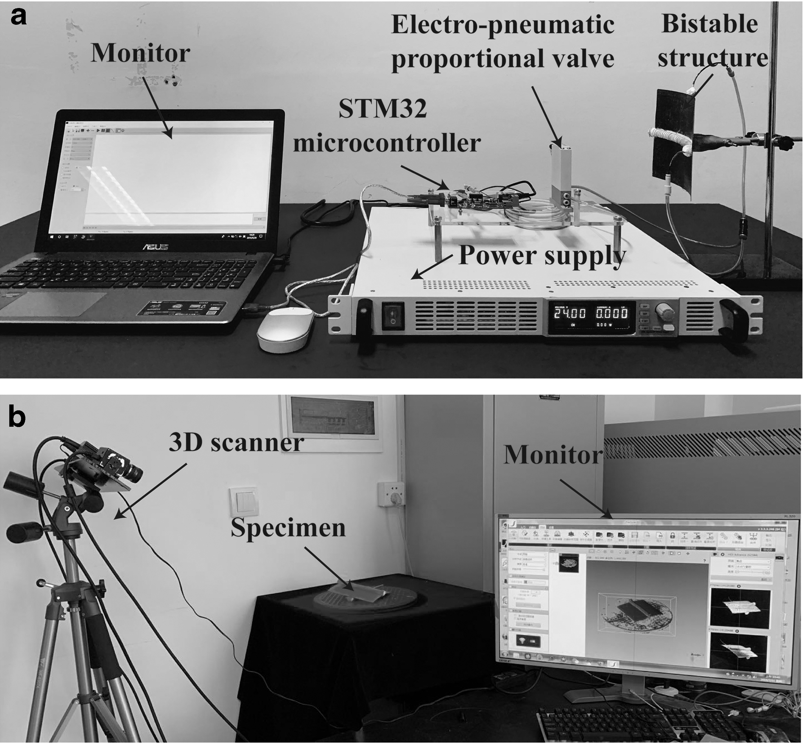
Experimental setup.
When the central chambers of pneumatic actuators are inflated with compressed air, the silicone rubber body can perform axial elongation; when the pneumatic actuators are fixed on the bistable laminate, the side of the silicone rubber body which is in contact with the bistable laminate cannot be elongated. Thus, the pneumatic actuator can only perform a bending action that will generate a moment to drive the stable state transition of the bistable structure.
During the experiment, the air pressure in the pneumatic actuator was gradually increased until the state transition of the bistable structure was reached. The critical air pressures required to induce the snap-through and snap-back processes were measured during the experiments. These processes were captured by a camera, and the response time was obtained using a video analysis software.
This study aims to determine whether the pneumatic actuator can drive the bistable laminates to achieve transformation between two equilibrium configurations, while ensuring that the curvatures of bistable laminates remain constant compared with the response under a mechanical load using a universal tensile machine. The curvature of the bistable structure was measured by a 3D scanner, which is shown in Figure 3b. After postprocessing the scanned file with Geomagic Studio software and using 3D reconstruction technology, a 3D image of a highly accurate bistable structure was obtained, improving the accuracy of the experimental results. Simultaneously, the model was remeshed in ABAQUS, and node coordinates were obtained to describe the geometric shapes of the bistable structures. The curvature and radius of curvature of the bistable laminates in the first and second stable states were obtained by performing calculations using MATLAB.
Numerical Simulation
In this section, the curing, snap-through, and snap-back processes of the unsymmetrical laminates actuated by pneumatic actuators were simulated using the commercial FE code ABAQUS (Dassault System), using a static analysis to obtain the simulation results and compare them with the experimental results, thereby verifying the accuracy of the FE model. The material parameters of unsymmetrical laminates used in the simulation are listed in Table 2. Most soft pneumatic actuators are representatively composed of hyperelastic materials, such as silicone rubber, making the modeling of soft pneumatic actuators challenging. As it is usually difficult to predict the deformation before fabricating a physical prototype, FEM is effective for predicting the specific performance of soft pneumatic actuators. 45
Before the simulations, the elastomeric samples (E615; Shenzhen HongYeJie Technology Co. Ltd.) used to fabricate the pneumatic actuators were tested according to the standard DIN 53504-S3A:1994 at an extension rate of 50 mm/min until breakage using a universal tensile testing machine. Because of the hyperelastic property of the silicone rubber, an incompressible hyperelastic Yeoh model 46 was used to describe its nonlinear behavior. Stress–strain data from experimental results were imported into ABAQUS, and material curve fitting was performed for the hyperelastic Yeoh model. The uniaxial tensile data were plotted and fitted with the Yeoh model. The material coefficients were obtained as C10 = 0.0412, C20 = 0.0072, and C30 = 0.0047.
The FE model of the structure was composed of the unsymmetrical laminates and pneumatic actuators. The unsymmetrical laminates were created using the composite layup option. The stacking sequence of the composite laminates was [0/90], and the thickness of a single layer (t) was set for the experiment. To simplify the calculation, we imported a simplified 3D model of pneumatic actuators into ABAQUS. To make the simulation results more accurate, and to obtain a simplified model, the tie option was utilized for the connections between unsymmetrical laminates and pneumatic actuators.
The unsymmetrical laminates were meshed by the S4R shell element to provide more accurate results and significantly reduce the computational time. Linear hexahedral-solid hybrid elements with reduced integration (Abaqus element type C3D8RH) were adopted for the silicone rubber of pneumatic actuators. For the radial-limiting wire, shell elements were used (ABAQUS element type S4R), which were connected to the pneumatic actuation by tie constraints. The material of the radial-limiting wire was modeled as linear elastic (Young's modulus of E = 20,600 MPa and a Poisson's ratio of v = 0.3). The unsymmetrical laminates and pneumatic actuators were assembled as per the three arrangement methods mentioned earlier.
To accurately determine the minimum forces required for the reconfiguration of bistable laminates, five analysis steps were established: Step 1 was the curing process of unsymmetrical laminates—an initial temperature field reflecting the elevated curing temperature was applied at this point, the temperature field was then modified to room temperature, and the originally flat laminates became bistable. In the second load step, pressure was applied to all internal walls of the air chambers of one pneumatic actuator, which triggered an unsymmetrical laminate transition from the first stable state to another stable state. In the third load step, the load applied in Step 2 was withdrawn to check whether the deformation of the bistable structure could be maintained without a sustained external force. Similarly, pressure was applied to another pneumatic actuator to achieve the snap-back process in Step 4, and the pressure was withdrawn to verify the bistable characteristic.
With the increase in the applied loads at each step, the transition process became unstable and large deformations occurred. To overcome this instability, the nonlinear large deformation option “Nlgeom” was set to “on,” and “Automatic Stabilization” was set according to the default parameters, with the aim of making the simulation results converge more easily. After applying pressure on the internal surfaces, the bending deformation, stress distribution, and the snap-through and snap-back processes of the bistable structure were determined.
Results and Discussion
This section shows the various experiments and FE results for determining the characteristics of the deformation processes of bistable structures. The first subsection studies the optimal arrangement of pneumatic actuators. The second subsection considers the actuation of pneumatic actuators and its actuating condition, that is, critical air pressure and response time for the snap-through and snap-back of bistable structures. The experimental results are then compared with the numerical simulation results obtained using ABAQUS and show that pneumatic actuators successfully generate the bending moment to achieve snap-through and snap-back of the bistable structures. The third subsection shows that the out-of-plane and shape characteristics of bistable structures were captured in the experiments, and the results are compared with the FE results.
Optimal arrangement of pneumatic actuators
In this section, pneumatic actuator B (abbreviated as Pneu B) is the object of discussion. When experimenting with the x-direction arrangement, the bistable laminate transitioned from one state to another as the air pressure in the pneumatic actuator gradually increased to 0.108 MPa. However, snap-back could not be achieved because the direction of the pneumatic actuator in the second state was perpendicular to the direction of curvature of the laminate, and the force required to actuate the bistable laminate at this location was much greater than the force required to actuate the laminate when the actuator was oriented along the curvature. When the pneumatic actuator on the lower surface of the laminate was driven, the actuator on the upper surface interfered with the snap-back behavior; it was also necessary to overcome the resistance caused by the bending of the upper surface actuator.
When the y-direction arrangement was adopted, the direction of the actuator was perpendicular to the direction of the curvature of the laminate. Similarly, snap-through could not be achieved. When the laminate was in the second state, the direction of the actuator was along the direction of curvature of the laminate, and the pressure in the pneumatic actuator reached 0.108 MPa. Here, snap-back could be achieved. When the cross-arrangement was adopted, the air pressure in the actuator on the upper or lower surfaces reached 0.09 MPa, and snap-through and snap-back of the bistable laminate could be achieved.
Comparisons were made between the curvature and curvature radius of the two configurations of the bistable laminate with different arrangements actuated by the pneumatic actuators and mechanical load. Table 3 shows that the curvature of the bistable laminate was minimally affected by cross-arrangement of the pneumatic actuators. Meanwhile, the bistable laminates could simultaneously achieve snap-through and snap-back under the pneumatic load. Based on the evaluation conditions presented above, we determined that the cross-arrangement is optimal. Subsequent discussions will consider this arrangement of pneumatic actuators.
Curvature Analysis
Critical pressure and response time
To actuate the snap-through and snap-back of the bistable laminates, the snap-through and snap-back sequences were recorded using a camera, as shown in Figure 4a and b. Actuation with Pneu A for the snap-through motion took 0.47 s under an air pressure of 0.207 MPa, while that for the snap-back motion took 0.17 s at 0.207 MPa. When we recorded the snapping action of the bistable structure, it was difficult to synchronize simultaneously the duration of the snapping action. This asymmetric actuation arose from the difference between the driving forces of the snap-through and snap-back processes. Figure 4c shows the load-displacement curves of the snap-through and snap-back actions of the bistable laminates driven by a mechanical load with a universal testing machine; the load testing results show that the driving forces for snap-through and snap-back are different.

Processes of snap-through and snap-back actions.
Cantera et al. 47 explained that the differences between the snap-through and snap-back phenomena could be explained by the possible thickness differences between the layers at 0 and 90. In addition, there are some differences in the curvatures of the two stable states of the bistable structure prepared in these experiments. We believe that this may be because (1) the fiber angle of the carbon fiber prepreg may have deviated during laying, and (2) the boundary conditions of bistable laminates during cooling led to different stable state curvatures. Thus, it is easier for snap-back to occur compared to snap-through with a shorter loading time. Nevertheless, using the naked eye, it was difficult to determine the unsynchronized actuation of the snap-through and snap-back processes of the bistable structures.
For the bistable solution to be obtained under the action of a bending moment, the load generated by the pneumatic actuation should be greater than the minimum force required for transitions. The air pressure in the pneumatic actuator decreased when the second stable configuration was obtained; otherwise, the air pressure increased. The critical pressures required for mutations can be approximately considered as the trigger pressure.
The critical pressures for the snap-through and snap-back processes were recorded using experiments, and the magnitudes of these air pressures were compared with the FE results presented in Table 4. The FE results are in good agreement with the experimental results; the minimum difference between the experiments and FE is 2.94%. It should be noted that the pneumatic actuator with a larger chamber cross-section area can trigger the transition under lower pressure. Meanwhile, the experimental and FE results show that the pressure required to snap-through was larger than that required for snap-back—a trend that is also consistent with the load-displacement curve of the bistable structure.
Critical Pressure of Experiments and Finite Element Results
FE, finite element.
Because the frequency of actuation between the snap-through and snap-back motions depends on the air pressure and geometric parameters of soft pneumatic actuation, the response times for the snap-through and snap-back actions were measured experimentally as the air pressure was changed. The corresponding results indicate that when the STM32 microcontrollers started to send an electric signal to the electrical proportional valve, the pneumatic actuator was inflated into compressed air until the snap-through or snap-back of the bistable structures was completed.
Figure 5 compares the response times for three kinds of pneumatic actuators as the air pressure increased for the snap-through and snap-back actions. It is evident that the response time gradually decreased when the air pressure increased in the chambers for both, snap-through and snap-back, driven by the three actuators. Subsequently, when the air pressure reached a certain value and increased continuously, the response time tended toward a constant value and would not continue to decrease because the driving force was greater than the load needed for state transition at this time. In addition, the response time of the bistable structure actuated by the three actuators may have tended to be the same if the driving pressure had continued to increase.

Curves showing variation of response time with air pressure for snap-through and snap-back actions.
It should be noted that the pressure required by Pneu C was the smallest, while that required by Pneu A was largest; that is, for the actuator with the air chamber having the larger cross-sectional area, it would be easier to drive the bistable structure to achieve deformation under the same response time. Table 5 shows the maximum and minimum response times for the snap-through and snap-back actions. The maximum response time indicates the driving time of state transition under critical air pressure, and the minimum response time was obtained when the pressure increased and when time did not decrease.
Maximum and Minimum Response Times for Snap-Through and Snap-back Actions
Out-of-plane deformation
The ABAQUS simulation results are shown in Figure 6, which depict the snap-through and snap-back processes of the bistable structures actuated by pneumatic actuators based on optimal arrangements. As the actuator performed the bending motion, the CFRP laminate edge flattened until the pneumatic actuator was as straight as possible. As the actuator became straighter, the bending moment increased. When the bending moment reached the maximum load, the laminate edge bent in the other direction, and the laminate started to deform. After snap-through, the entire configuration of the laminate remained in the other stable shape without the external force. Similarly, the laminate could be deformed to remain in the initial stable configuration after snap-back.

Snap-through and snap-back processes obtained from simulation results.
The current bistable composite laminates actuated by three kinds of pneumatic actuators generated two stable solutions for each configuration. Figure 7 shows the out-of-plane displacement for both stable shapes at room temperature. The FE results (surface) and experimental results (points) are superimposed on each other to depict the differences. Upon more detailed analysis of the experimental and FE data, it can be observed that for stable configurations of bistable laminates actuated by three kinds of pneumatic actuators, the FE and experimental results are in very good agreement, with very minor differences near the edges.

Comparison of bistable shapes for experiments and FE results; the left and right sides show the two stable shapes.
The two stable shapes of bistable laminates actuated by Pneu A are depicted in Figure 7a, and the differences in the FE and experimental results are small compared to the stable shapes actuated by Pneu B and Pneu C, which are depicted in Figure 7b and c, respectively. In addition, from the perspective of stable configurations of bistable laminates driven by three kinds of pneumatic actuators, the difference between the FE and experimental results in the first stable configuration is smaller than that in the second stable configuration. The experimental results and FE results are closest for all stable configurations at the center section of bistable laminates where the edge effects were minimal.
Table 6 shows the out-of-plane displacement predicted by FE and scanned-in experiments at the edges of bistable laminates. The out-of-plane displacement of the second stable states was larger than the corresponding displacement in the first stable states of the bistable laminates. As the different pneumatic actuators drove the stable state transition of the bistable laminates, there was a gradual increase in the error between the experimental and FE results. The possible main reasons for the difference between the simulation and experiments are as follows:
Comparison of Out-of-Plane Deformation for Experimental and Finite Element Results
(1) The installation order of pneumatic actuators in the experiment and simulation may have been inconsistent. In the experimental preparation, the bistable structure was prepared first, following which the prepared pneumatic actuator was adhered to the bistable structure. While the prepared pneumatic actuator was straight in the initial state, when the pneumatic actuator was bonded to the bistable structure in a cross-arrangement, the bending of the pneumatic actuator generated an elastic force to restore it to its original shape, which will affect the curvatures of the bistable structure. Moreover, from Pneu A to Pneu C, it was more difficult for the pneumatic actuator to bend from its initial straight state as the structure of the pneumatic actuator was larger, while Pneu C was adhered to the bistable structure in a bent state, which produced a larger elastic force. However, in the simulation, the pneumatic actuator was installed on the uncured laminates during assembly, following which a temperature field was applied to the uncured laminates to confer bistable characteristics.
(2) Although the mass of the pneumatic actuator was negligible (<10 g), gravity may have a slight effect on the experiment, as the effect of gravity on the out-of-plane displacement of the overall structure gradually increased as the size of the pneumatic actuator increased.
(3) Some errors occurred during the experimental fabrication.
(4) There exist some differences in the material properties between the experiments and simulation.
However, the best match in the out-of-plane displacement between the experimental and FE results was obtained for the first stable configuration and second stable configuration actuated by the Pneu A actuator.
Pneumatically actuated soft gripper
Interestingly, the cross-ply CFRP laminates exhibit three features: two stable configurations without the continuous application of an external force, an orthogonal curvature shape, and the snap-through and snap-back actions, both of which originate from the bistability. Based on the snap-through and snap-back action actuated by the pneumatic actuators, changes from one stable state to the other are very fast, as also described in the previous sections.
Therefore, to induce shape retention, we could use the bistable laminates in key areas of the soft gripper. The soft gripper comprises three components, as shown in Figure 8a: two bistable laminates, four pneumatic actuators, and a supporter that holds the gripper. The central parts of the curved edges of the two bistable laminates were fixed together with connectors and mounted on the support. The four pneumatic actuators were installed on the bistable laminates using the method that yielded the optimal arrangement. When the pneumatic actuators were activated by air pressure, their bending motion generated the bending moment to drive the bistable laminates to achieve a shape transition, that is, the soft gripper transited from the opening state to the closing state. The shape of the bent actuator was then retained without any pressure supply.

The soft gripper.
The gripping mechanism was realized by changing the size of the cavity of the soft gripper. As shown in Figure 8b, the deformation of the CFRP laminates generated a recovery force that enabled the object to be gripped when the object was larger than the cavity of the soft gripper. G represents the gravity of the object, F represents the recovery force generated by the deformed laminates for grasping the object, and F′ represents the reaction force of the object acting on the CFRP laminates.
When the size of the object is particularly large, highly deformed laminates can generate a large recovery force and also experience a large reaction force, which is sufficient to cause transition of the bistable laminates to the second stable state, so that the object cannot be grasped. As shown in Figure 8c, this gripper was unable to grasp when the size of the balloon gradually increased, and the bistable structures changed the shape from the second stable configuration to the first stable configuration. Another situation where grasping is not possible is when the weight of the object is greater than the gripping force of the gripper, which is also related to the coefficient of friction. After repeated experiments, the soft gripper could grip objects with various shapes (round, rectangular, triangular, or irregular) even when the pressure returned to the initial state in the pneumatic actuators, as shown in Figure 9a.

Demonstration of proposed gripper.
According to the gripping mechanism of this gripper, the gripping performance is determined by the object size. The above demonstrations of grabbing prove that the gripper is very adaptable to objects with different sizes. However, it has been reported that gripping a deformable object has always been a challenge for existing grippers 48 ; soft and deformable objects are often difficult to handle by fingered systems48,49 and are usually picked up by electroadhesion50,51 or gecko adhesion.52,53
While deformable objects are widely used in our life and engineering applications, deformable structures have simultaneously emerged into the limelight. A representative example is the three-dimensional reconfigurable structure introduced by Overvelde et al., 54 which was inspired by the structural diversity and foldability of prismatic geometries. If a gripper with a simple structure can be used to grasp deformable objects, this will expand the application field of soft robotic grippers.
This gripper with a bistable structure exhibited sufficient compliance, such that the deformed CFRP laminates automatically accommodated the deformation of objects. Inflating or deflating balloons are sufficiently representative of deformable objects. As shown in Figure 9b, the gripper could keep gripping the balloon as it gradually shrank. The gripper could also grasp the inflating objects stably, such as the balloon in Figure 9c. At the same time, the structure of the gripper itself did not affect the deformation of objects. The experimental results show that the active deformation of the CFRP laminates in this gripper can be well self-adapted to the volume reduction or expansion of objects with a simple structure.
It is difficult to measure the gripping force due to its dependency on the contact angle. This section introduces a simple method designed to obtain the gripping force for evaluating the gripping performance. The proposed soft gripper was used to grip containers of different sizes, and a sufficient number of metal parts were gradually added to the container until the gripper could not grip it, that is, the bistable laminates began to change from the initial state to the second stable configuration, which showed an approximate maximum gripping capacity during testing. It is reasonable to believe that the total weight of the container and metal parts is approximately equal to the gripping force.
As shown in Figure 10a, the soft gripper was used to grip a square box filled with metal parts without pressure applied, and after performing several repeated tests and calculating the average value, the available weight for gripping was 77 g. We also obtained the relationship between the gripping capacity and the size of the objects by constantly adjusting the size of the objects, as shown in Figure 10b. The blue area indicates the range of the size and weight of objects that could be grasped by this soft gripper without continuous pressure applied. When the size of the object gradually increased, the weight of the graspable object increased sharply. Because the increase in the size of the objects caused the deformation of the bistable CFRP laminates to increase, the larger recovery force generated by the bistable laminate allowed it to grab a heavier object. The experimental results show that the maximum weight that can be grasped is 89 g when the object size is 125 mm.

Experiment testing for proposed gripper.
In addition, when the two pneumatic actuators on the outside of the gripper continued to be filled with air pressure, the gripper could grasp a heavier and bigger object because the bistable structure did not easily transition from the first stable state to the second stable state at this time. The yellow area of Figure 10b indicates the size and weight of objects that could be grasped when the pneumatic actuations were continuously pressurized (0.234 MPa). After performing several repeated experiments, the results show that the allowed weight of gripping increased by 18.2% compared with the pneumatic actuations of the gripper without pressure applied and that the maximum weight that could be grasped was 105 g.
In addition, we explored the weight of objects that could be grabbed under different pressures. As shown in Figure 10c, this gripper gripped four different sizes of objects. The results illustrate that the weight of the graspable object gradually increased as the pressure increased, which also satisfies the rule that the gripper is easier to grab objects with larger size. However, because the gripping force is related to the bending stiffness of the laminates, the gripping force is insufficient to grip a heavier object. A possible way of increasing the gripping force is changing the thickness of the laminate and curvature of the second stable configuration.
As discussed earlier, the mechanism of switching between bistable states is used to grasp an object. In this work, air pressure was only applied during the closing and opening actions of the gripper, while most grippers would require a continuous supply of power to actuate the robotic arm throughout gripping. In our work, the air pressure was supplied by a compressed air tank (750-30L; Aotus Industry and Trade Co., Ltd.) with a capacity of 30 L. And the rated power of the air compressor is 750 W, and the air storage capacity of the cylinder is 60 L/min.
Therefore, the energy consumed when the air cavity of the air compressor is filled with gas can be estimated as Uc = P × tc = 750 W × 30 s = 22,500 J. According to the cross-sectional area of the air chamber of the designed pneumatic actuator, the volume of air chamber can be calculated as V = 1.073 × 10⁻³ L. Therefore, it can be considered that after the cylinder of the air compressor is filled with air, the pneumatic actuator can drive a bistable structure to complete the transformation 27,958 times and consume only 0.8047 J of energy each time. The air pressure inside the pneumatic actuator was adjusted using the electropneumatic proportional valve (ITV0050-3BS; SMC Corporation), which was controlled by the voltage provided by a STM32 single-chip computer, with an input voltage supplied by a 24 V constant voltage power supply. During experimentation, the current flow was recorded to be I = 30.2 mA when the electropneumatic proportional valve supplied pressure for the closing or opening action of the gripper.
Thus, the total energy consumption for each grasping action can be estimated as U = V × I × t + 0.8047 J × 2 = 24 V × 0.0302A × 0.33 s + 0.8047 J × 2 = 1.8485 J. The gripper based on the bistable CFRP structure only consumed 0.0207 J/g of energy to complete one grasping motion. The current low-energy consuming gripper based on a bistable dielectric elastomer actuator would consume 0.1386 J energy when grabbing a 15 g object 55 ; that is, the energy consumed during grasping would be 0.00924 J/g.
Although compared with it, the proposed bistable gripper consumes slightly more energy during the grasping process, the energy consumption is related to the types of air compressors, electropneumatic proportional valves, and single-chip computers. We believe that the energy consumed by the gripper in the process of grasping objects will be greatly reduced if low-power experimental equipment is used and the bistable structure and the pneumatic actuator structure are further optimized. In general, there are certain advantages with regard to energy consumption compared with most grippers which require a continuous supply of power.
Conclusions and Future Work
In this article, we presented a self-adaptive soft gripper that structurally integrated with bistable laminates to induce shape retention. We designed and tested pneumatic actuators which could achieve the snap-through and snap-back of bistable laminates to close and open this soft gripper. Furthermore, the snap-through and snap-back motions, as well as the out-of-plane deformations, were analyzed, and the results demonstrated that the proposed soft gripper can respond at the millisecond level under low pressure.
Bistability enabled the soft gripper to have a simpler structural design, while two stable configurations allowed the creation of a rapid and large morphing motion for the gripping action, regardless of the infinite degrees of freedom of the structure, and maintain the shape when gripping objects with different sizes even when the pressure was reduced to the initial state. Simultaneously, this gripper structure exhibited sufficient compliance and self-adaption, and the deformed CFRP laminates could automatically accommodate the deformation of objects. Functional tests verified that the proposed soft gripper is versatile and adaptable to gripping objects of various shapes and sizes.
In the current soft grippers, the bistable laminates have a low gripping force and limited bending angle. Future work will involve structural optimizations of this gripper to solve these problems, including chamber optimization of pneumatic actuations, stiffness studies of bistable structures, and the arrangement of actuations, including testing of their structural characteristics.
We believe that the results prove that the newly developed optimized grippers are versatile and adaptable and are promising for application in special environments with a locked air supply such as underwater or space. In these environments, the proposed gripper will enable rapid and stable grasping of objects without a continuous energy input, which will effectively conserve the air supply. In addition, the grippers will be tested in extreme environments of low pressure and high temperature to further evaluate their gripping performance. We expect that the gripper will be able to perform grasping or assembly tasks in both underwater and space, aid in the design of soft robots that allow shape retention, and serve as a reference for robotic applications.
Footnotes
Author Disclosure Statement
No competing financial interests exist.
Funding Information
This research was supported by the National Natural Science Foundation of China (Grant Nos. 52075492, 51675485, 51775510, 11972323), the Zhejiang Provincial Natural Science Foundation of China (Grant No. LR18E050002), and the Special Research Foundation of Education Bureau of Zhejiang Province, China (Grant No. Y201941851).