




Abstract
Owing to their compliance, lightweight, and high force density characteristics, pneumatic actuation systems have been widely implemented in various soft robots. However, pneumatic actuation systems exhibit low efficiency, poor control performance, and high noise; these make it extremely challenging to widely employ a pneumatic actuation system in mobile robots. To overcome these limitations, many researches were conducted on recycling the compressed air within such systems. However, the proposed approaches do not consider the system efficiency and exhaust performance of pneumatic systems. Therefore, this article proposes a recirculation system using a novel soft re-air valve based on the cardiac structure of fish. In particular, the proposed recirculation system recycles the compressed air to improve the system efficiency and pressurizing performance, and the soft re-air valve simultaneously prevents a decrease in the depressurizing performance. For the validation of the proposed scheme, experiments were conducted to evaluate the system efficiency, control performance, and exhaust noise. In contrast to conventional pneumatic systems, the experimental results revealed that the proposed system increased the overall system efficiency by 47.58%, reduced the position root mean square error by 8.16%, and reduced the exhaust noise by 47.52%.
Introduction
Soft robotics is an emerging field of interest in robotics research. By replacing conventional rigid and heavy actuators with soft and lightweight actuators, numerous researchers have attempted to provide a safe environment for physical human–robot interactions.1–3 Rigid actuators, such as those based on electric motors, are high speed and precise 4 ; however, they require high gear ratios to compensate for their low force densities. Moreover, soft actuators are lightweight and capable of demonstrating high force densities. In addition, the back-drivable and compliant nature of soft actuators exhibit impact resistance to external disturbances. 5 Hence, various soft actuators such as shape memory alloys, 6 tendon-driven actuators,7,8 and pneumatic artificial muscle (PAM) have been extensively researched for applications in soft robotics.9,10
Among the potential actuator schemes, pneumatic systems are one of the most widely used system types in soft robotics. In particular, PAMs can exert relatively higher force densities at a lower cost than other soft actuators. 11 In addition, their higher contraction ratios provide robots with a wide range of motion. 12 Furthermore, utilizing air as an energy source allows for safe operation and simple maintenance. 13
Despite such advantages, it is very challenging to employ PAMs in soft mobile robots (i.e., wearable robots and prosthetics) owing to their drawbacks related to low system efficiencies, relatively slow responses, loud exhaust noise, and large overheads such as compressors and air reservoirs. 14 First, pneumatic systems exhibit low energy efficiencies, given that the compressed air is discarded after use. Second, a considerable amount of time is required for pressurization and exhaust, thus limiting the control performances. Third, excessive noise is generated when the compressed air is discharged from the systems. Furthermore, pneumatic systems require large compressors for continuously stable operations, which is significantly disadvantageous for mobile robots.
To address these drawbacks, several researchers proposed recycling methods for the compressed air that circulates within pneumatic systems. Otto connected an air tank between an actuator outlet and a pump inlet to reduce the noise during the discharge of the compressed air. 15 Bosua developed a system to recycle low-pressure air and high-pressure exhaust air for enhanced control performance. 16 JP Patent No. 03676669 (2005) utilized a vacuum valve for the transmission of the compressed air between two actuators. 17 Moreover, given that 17 system requires a vacuum pump to exhaust the compressed air, additional overhead is incurred by the system.
Although the abovementioned approaches demonstrate the possibilities of recycling the compressed air, the trade-off between the control performance and system efficiency is not considered. Moreover, during the recycling of compressed air to increase system efficiency, the high-pressure compressed air induces a compressor overload, which results in a significant delay in the discharging time. This reduction of the depressurizing performance leads to severe drawbacks during the control of the actuator.
To improve both the system efficiency and control performance, an air recirculation system was developed in this study using a soft re-air valve. The proposed system recycles almost all the air used within the pneumatic actuation system, thus enhancing the system efficiency. The design of the soft re-air valve is based on the cardiac structure of fish, which regulates blood pressure and facilitates blood flow by changes in volume. 18 As depicted in Figure 1, the proposed valve is composed of a soft outer wall with low elasticity to passively store the energy of the compressed air in the form of elastic energy. Thus, the system efficiency is increased, and the depressurizing performance of the PAMs is improved. The proposed system therefore allows for the efficient recycling of the compressed air without impacting the depressurizing performance. Furthermore, the proposed system can reduce the noise generated during exhaust.

This article is organized as follows. In the Materials and Methods section, the air recirculation system is presented, in addition to design methods for the soft re-air valve, followed by simulation results of a simple system model in the System Simulation section. In the Fabrication of Soft Re-Air Valve section, a detailed discussion on the fabrication method of the soft re-air valve is presented. Thereafter, the experimental setup and results of the soft re-air valve are discussed in the Results and Discussion section, followed by the conclusions and scope for future research in the Conclusions section.
Materials and Methods
An air recirculation system
To increase the system efficiency, a recirculation system that circulates the compressed air without release from the system was developed. Moreover, the proposed system improves the system efficiency by recycling the compressed air and reduces the noise by the elimination of the exhaust process.
As shown in Figure 2B, the mass flow rate of the air recirculation system can be derived using the Bernoulli equation, as expressed by Equation (1):

Actuation concept of each pneumatic system.
where
Under the assumption that
Therefore,
In addition, in Figure 2B, the mass flow rate from the hard reservoir to the compressor can be expressed as follows:
By substituting Equation (3) into Equation (4),
where
Similarly, the mass flow rate of the conventional pneumatic system in Figure 2A can be expressed as follows:
where
When recirculating the compressed air, the pressure of the hard reservoir is higher than the atmospheric pressure, thus satisfying the following condition:
During the operation of the compressor, the air-tank pressure variation is dependent on the mass flow rate to the compressor. From the ideal gas equation, the differential pressure of the air-tank in Figure 2B can be derived as follows:
where
As can be seen from Equations (5) and (8), with an increase in the internal hard reservoir pressure
However, with respect to the depressurizing performance, the direct recycling of high-pressure compressed air into the compressor is not suitable for applications. In particular, the direct recycling of the excessively high-pressure air may have a significant impact on the depressurizing performance due to the residual air. It should be noted that the residual pressure is defined as the pressure of the remaining air within the PAM.
Similar to Equation (5), the mass flow rate from the PAM to the hard reservoir can be expressed as follows:
where
For a conventional pneumatic system (Fig. 2A), the residual pressure (gauge pressure) of the PAM immediately after the discharge of compressed air can be expressed based on Boyle's law, as follows:
where
Similarly, in the air recirculation system with a hard reservoir (Fig. 2B), the residual pressure of the PAM during the discharge of compressed air was derived under the assumption that the PAM pressure was higher than hard reservoir pressure (i.e.,
where
Equation (12) indicates that the residual pressure of the recirculation system (B) is always higher than that of the conventional pneumatic system (A). This implies that the depressurizing performance of the recirculation system is reduced at the cost of the system efficiency. Consequently, a reduction of the depressurizing performance adversely affects the control performance of the PAMs; thus, a novel solution for the compensation of the poor control performance is required.
Soft re-air valve
The residual air accumulates within the PAMs during the recycling of the compressed air, and the residual pressure has an influence on the discharge rate. Moreover, the exhaust of compressed air to the atmosphere would result in a lower system efficiency and significant noise.
To address the slow discharge problem, a soft re-air valve based on the cardiac structure of fish was designed and developed. In particular, the aforementioned cardiac structure controls blood flow by changing its volume to adjust blood pressure. 18 With respect to the hard reservoir, its rigid outer wall prevents the release of the residual air from the PAM. Therefore, the outer wall of the soft re-air valve should be fabricated using a soft material (Dragon Skin 10; Smooth-On, Inc.), which allows for the expansion and contraction of the valve with respect to the air pressure. This also reduces the residual pressure in the soft re-air valve according to Boyle's law.
The pressure of the residual air
where
Given the inflation of the soft re-air valve due to the high pressure of the discharged air, the volume of the valve after exhaust satisfies the following inequality:
Based on the Equations (11), (13), and (14), the residual pressure within the system (B) can be expressed as follows:
Equations (13)–(15) indicate that the residual pressure in the PAM can be reduced if the outer wall of the soft re-air valve is composed of a soft material. In addition, the soft outer wall of the soft re-air valve stores the compressed air in the form of elastic energy, which is then reused to supplement the energy loss due to the reduced pressure.
However, an outer wall made of a soft material does not improve the efficiency of the recirculation system. For example, if the initial volume of the soft re-air valve is reduced by the suction of the compressor, the energy of the recycled air is used to restore the original state of the soft re-air valve. If the energy of the compressed air is lost during the recycling process, the overall system efficiency is decreased. Therefore, to prevent the volume of the soft re-air valve from decreasing below the initial volume, (1) a plastic inner supporter is required. In addition, backflow is a critical factor that reduces the system efficiency and the depressurizing performance. Therefore, (2) a bioinspired structure of the soft re-air valve is required.
(1) A plastic inner supporter was designed using acrylonitrile butadiene styrene material and inserted within the soft re-air valve. It should be noted that the inner supporter prevents the volume of the soft re-air valve from decreasing below the initial volume when the air inside the valve is insufficient and the internal pressure of the soft re-air valve is negative owing to the compressor. Moreover, the compressor can receive air from the atmosphere more easily via the connected check valve than the soft re-air valve. In addition, when the internal pressure of the soft re-air valve is negative, the depressurizing performance is improved based on Equation (16):
where
(2) A scheme based on the cardiac structure of fish was then implemented to allow for airflow with minimum interference. Conventional check valves were designed and applied to ensure unidirectional airflow and to reduce the airflow rate by interrupting the flow of the air. Moreover, the proposed system prevents air backflow and minimizes the restriction of the airflow. Therefore, the employed structure can effectively enhance the performance of the soft re-air valve.
System Simulation
To validate the performance of the proposed system, the pressurizing and depressurizing performances of three different pneumatic systems were compared via a simulation.
To compare the performances of the recirculation systems, the pressure in each component such as the air-tank, soft re-air valve, and the PAMs was calculated. Moreover, (1) the volume of the components and (2) pressure variations among the components were calculated, as required.
(1) To calculate the volume of the soft re-air valve for the simulation, it was assumed that the soft re-air valve is composed of two basic spheres, as shown in Figure 3A. Given that the outer wall of the soft re-air valve is elastic, the lengths

where k is the outer wall stiffness of the soft re-air valve, and
(2) The differential pressure equation was derived based on the mass flow at the input and the output, in addition to the volume of the system components. The pressure variations of each component mentioned in Figure 3A were derived using the ideal gas equation, as follows:
where
where
Finally, the pressures of the air-tank and the PAMs were calculated based on Equations (17)–(23), and simulations were conducted to evaluate the pressures of each component of the pneumatic systems. The compressor was set to operate when the air-tank pressure decreases below 3.2 bar and then set to terminate operation when the air-tank pressure exceeds 3.8 bar. Upon the termination of the compressor operation, the pressure variation of the air-tank (
From the simulation, the soft outer wall of the soft re-air valve was found to prevent high-pressure residual air buildup within the PAMs when compared with the function of a hard outer wall (Fig. 3C). In addition, the air-tank pressure of the proposed system was found to be higher than that of the typical pneumatic system, thus indicating an improved pressurizing performance (Fig. 3B).
Fabrication of Soft Re-Air Valve
The fabrication process of the soft re-air valve is shown in Figure 4. The outer wall of the soft re-air valve is made of high-performance silicon rubber (Dragon Skin 10), which was selected owing to its sufficient stiffness. Using a low-stiffness material allows for the soft re-air valve to exhibit a large volume change, thus resulting in a reduced system efficiency. The relatively high stiffness of the silicon rubber provides a high restoring force and constrains excessive changes in volume.

Schematic of fabrication process consisting of CAD drawing of the mold and the inner supporter.
The objective of the rigid supporter is to prevent the compressor from changing the initial volume of the soft re-air valve during the intake of air into the pneumatic actuator. Without a rigid supporter, there is a decrease in the initial volume of the soft re-air valve. When the compressed air is discharged from the PAMs, the potential energy of the compressed air is used to restore the valve to its initial volume. It should be noted that the efficiency of the recirculation system decreases, given that potential energy is expended for the restoration of the initial volume of the soft re-air valve. Moreover, the addition of a rigid supporter within the soft re-air valve eliminates this problem. The rigid supporter was therefore placed between the soft outer walls. Thereafter, the Sil-Poxy bonding agent was used to bond the outer walls for the prevention of air leakage. Furthermore, the solid supporters were not bonded.
Experiments and Discussion
An experimental test bed was designed, as shown in Figure 5. The test bed with 1 degrees of freedom (DOF) consists of a power supply, a control board, two compressors (D1008-23-01; Parker Hannifin Corp.), an air-tank, a soft re-air valve, a regulator (ITV1050; SMC Corp.), and an opposite pair of PAMs (DMSP10-150N-RM-CM; Festo Ltd.). For the experiment, the two compressors, with a flow rate of 12 L/min, were connected in series. The initial volumes of the air-tank, soft re-air valve, and PAM were ∼158, 76, and 47 mL, respectively.

One DOF rotational joint test bed setup for validation. DOF, degrees of freedom.
To verify the effectiveness of the proposed soft re-air valve, experiments were conducted with respect to (1) the improvement in efficiency and (2) its influence on the control performance. In addition, (3) a performance test was conducted on the bioproposed scheme to verify its applicability to the actual pneumatic systems.
(1) Efficiency test:
In the first experiment, the power consumption of the compressor was calculated based on current measurements to verify the efficiency of the proposed system. It should be noted that the currents were measured for the tasks that consumed the same amount of compressed air in each system. The process of the efficiency verification test is classified into two states. In State I, the same amount of the compressed air in the air-tank was used by the PAMs (Fig. 6A, B); and in State II, the compressor replenished the air-tank with the compressed air (Fig. 6C, D).

Efficiency experimental process and results.
In Figure 6E–J, the experimental results indicate that the proposed system filled the air-tank at a 57.64% higher speed and therefore improved the pressurizing performance, while requiring less current, in comparison with the conventional pneumatic system. Moreover, in Figure 8A, the power consumption of the proposed system was 47.58% less than that of the conventional pneumatic system.
(2) Pressurizing and depressurizing performance test:
In the second experiment, position tracking control was implemented, and the angle of the 1 DOF test bed was measured to determine the effects of the pressurizing and depressurizing performances. The position tracking was evaluated at a sinusoidal wave frequency of 0.25 Hz, which ranged from 0° to 7°. Because of the performance limitations of the small compressor, the experiments were conducted at 0.25 Hz. For comparison, the same small compressor was employed. In addition, noise was measured in a controlled environment with a high-end smartphone (SM-N976N; Samsung Electronics Co., Ltd.) to compare the operating sound and the exhausting sound of each system. In general, since the exhausting sound is greater than the operating sound, the value of the operating sound is assumed to be the average value of the measured data, whereas the value of the exhausting sound is assumed to be the maximum value of the measured data.
As shown in Figure 7B–D, the experimental results indicate that the recirculation system with a hard reservoir enhanced the pressurizing performance, and it was subjected to a low depressurizing performance. The conventional pneumatic system exhibited a significantly low pressurizing performance. However, the proposed system demonstrated an improved pressurizing performance and maintained the depressurizing performance. In addition, the position tracking error of the proposed system, which is also referred to as the root mean square error, was 8.16% less than that of the recirculation system with a hard reservoir (Fig. 8B).
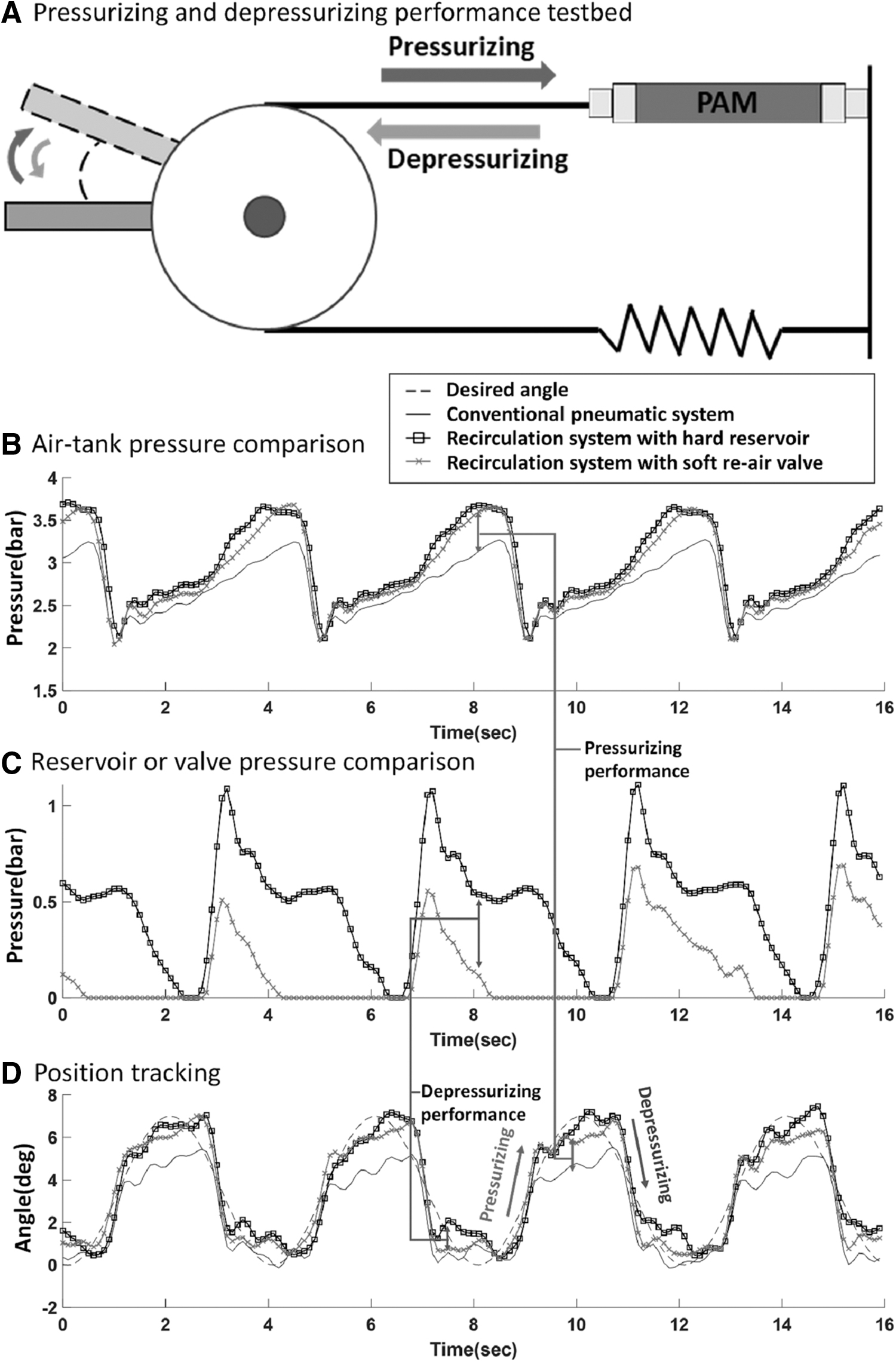
Test bed for evaluating pressurizing and depressurizing performance and experimental results.

In summary, the proposed system can improve the system efficiency and its actuation performance. In addition, the exhaust noise from the pneumatic systems can be considerably reduced. The noise of the proposed system was 47.52% (−5.6 dB) lower than that of the conventional system. Moreover, a comparison of the results of each system is presented in Table 1.
Comparison of Experimental Results
RMSE, root mean square error.
(3) Performance test in the antagonistic test bed:
For the third experiment, we used a new test bed with an antagonistic configuration. This test bed consists of four McKibben PAMs, each with its own regulators, to control the actuators. The outlets of all the regulators were connected to a single soft re-air valve with the same compressor used in the above experiment. In addition, the joint angle of the test bed was measured using an inertial measurement unit sensor.
A third experiment was conducted to evaluate the pressurizing and depressurizing performances in the test bed with an opposite pair of PAMs. Moreover, PAMs are typically employed in antagonistic configurations, where each pair of PAMs may have an adverse influence on the others. For example, a slight delay during the depressurization of a pair of PAMs can significantly reduce the position tracking performance. Especially for a sliding joint with antagonistic configuration, the residual pressure of each PAM not only interferes with the position tracking performance but also generates friction. Therefore, the test bed developed by Kim et al. was employed for verifying the interference of PAMs. 19 The experiment was conducted on the test bed developed by Kim et al., as shown in Figure 9A. This test bed consists of four handmade McKibben muscles and an ellipsoid contact joint. It should be noted that only 1 DOF was employed for the tracking performance test. Given that the objective was to evaluate the effect of the residual pressure of the PAM interference with the opposite PAM in the opposite pair, the experiment was conducted at 0.33 Hz with a range of motion of ±25°.

As shown in Figure 9B, the proposed system demonstrated a superior tracking performance than other systems. In particular, the conventional pneumatic system cannot provide compressed air owing to its excessively low pressurizing performance. In addition, the recirculation system with a hard reservoir exhibited a significantly low depressurizing performance and yielded similar results to the conventional pneumatic systems in the antagonistic test bed. Moreover, the proposed system demonstrated a remarkable performance with respect to the pressurization and exhaust processes. The experimental results presented above confirm the superior performance of the proposed system in the antagonistic test bed. The performance is significantly improved in systems where friction is generated by the force of PAM. This is because the residual pressure generates a PAM force, which applies friction to the joint.
Conclusions
Pneumatic actuation systems have advantages such as high force densities and lightweight. However, owing to the disadvantages of a low compressing efficiency, slow response, noise pollution, and excessive overhead, it is significantly difficult to apply such systems to soft mobile robots such as soft wearable robots.
To overcome these limitations, this article proposes a recirculation system that uses a soft re-air valve to effectively recycle the compressed air. The proposed recirculation system with the soft re-air valve was designed to improve the efficiency and control performance. The hyperelastic material of the proposed soft re-air valve stores the exhausting compressed air in the form of elastic energy during the recycling process. Thus, the depressurizing performance is significantly improved owing to the decrease in the compressed air pressure. Given that the compressed air is recycled for operation, the compressor efficiency and the pressurizing performance are improved. By using the soft re-air valve in recirculation systems, the depressurizing performance of pneumatic actuation systems can be significantly improved.
To validate the design parameters, the system efficiency (currents of the compressor), pressurizing performance (pressure of the air-tank), depressurizing performance (pressure of the PAM), and sound generated by the exhaust air were measured. The experimental results revealed that the proposed system with the soft re-air valve can reduce the power consumption by 47.58% and increase the control performance by 8.16%. The improved pressurizing and depressurizing performances are particularly evident in the test bed with a polar opposite PAM-pair configuration. The actuation performance of the PAMs can be significantly improved by reducing the PAM residual air, which reduces the effective range of motion. In addition, given that the compressed air is recycled instead of being exhausted, noise can be reduced by an average of 5.6 dB (∼47.52%). The weight overhead introduced to the system is minimal, given that the mass of the soft re-air valve only accounts for 100 g of the total system mass of 2.7 kg.
The proposed system is highly applicable to the pneumatic actuation systems in mobile robots. Furthermore, the scope of future research involves the development of an optimization method to enhance the performance of the soft re-air valve and the application of this system to soft wearable robots powered by PAMs.
Footnotes
Author Disclosure Statement
No competing financial interests exist.
Funding Information
This work was supported by the Industrial Technology Innovation Program (No. 20007058, Development of safe and comfortable human augmentation hybrid robot suit) funded by the Ministry of Trade, Industry and Energy (MOTIE, Korea). Also, this work was supported by the National Research Foundation of Korea (NRF) Grant funded by the Korean government (MIST) (No. NRF-2016R1A5A1938472). This research was also supported by the Chung-Ang University Graduate Research Scholarship in 2017.