
Abstract
A modular actuator construction consisting of smaller articulating units in series was designed to construct soft pneumatic actuators. These units are constructed to have a preferential bending direction using Mold Star 15 and Smooth-Sil 950 silicone. By changing the orientation of each unit, a different deformed actuator shape can be achieved. A design tool was developed where a genetic algorithm was coupled with a nonlinear finite element solver. This design tool optimizes the design using the genetic information available in the initial population over multiple generations and presents a candidate design that best resembles a desired profile specified as the objective function. A two-dimensional reduced order model was developed that reduces the time for each function evaluation from ≈20 min for a three-dimensional (3D) numerical analysis to ≈45 s. The design tool was tasked to solve design targets ranging from sine and cosine functions of various amplitudes to final actuator tip positions. In each case, the inflated actuator resembled the desired profile. Selected physical actuators were cast and tested. 3D scanning was used to capture the inflated shape and compared it to the numerical solution. A quantitative comparison showed a maximum average deviation of <2.5% of the uninflated actuator length between the physical and numerical models. The proposed design tool proved successful in designing shape matching actuators with close agreement to physical models.
Introduction
Soft pneumatic actuators (SPAs) have the distinct characteristic that their inflated deformed shape can mechanically be preprogrammed into the architecture of the actuator to yield complex three-dimensional (3D) shape changes. Actuators therefore assume a more prominent role in their functionality at the expense of a central control system, and the resulting deformation goes beyond what we expect when dealing with conventional actuators. 1 This trait of tuning various features during design and manufacturing to alter the inflated shape and performance has been investigated extensively.2–13 Introducing modularity has further been explored as a means of achieving faster turnaround times between designs in search of desired behavior.14–18 The ability to prescribe a desired performance or behavior and task a computer algorithm with producing the design has been researched within the generative design sphere with varying degrees of success.19–24 This article investigates the possibility of combining these various features to develop a design procedure where the desired inflated profile can be specified and the design that resembles that profile be output for manufacturing. A design tool that can assist with planar shape matching is therefore desired. Singh and Krishnan 25 also researched planar shape matching of a soft actuator. Their work however focused on fiber-reinforced soft actuators where a different strategy is used to alter the degree of bending than what is required from a pneumatic network (Pneu-net) type actuator. Furthermore, an analytical approach was followed where either a set of nonlinear equations need to be solved or a nondimensional chart based approach be used to calculate the fiber angle required for a specific degree of bending. This current article requires the setting up of a combinatorial optimization problem that is solved using a genetic algorithm (GA).
To facilitate this design algorithm, numerical design tools are utilized extensively to determine the performance of potential candidates. Some of the earliest design work in soft robots being aided by numerical tools was in selecting the cross-sectional shape of a bending actuator to maximize tip displacement for a given pressure. 26 Other early work using numerical simulations was related to the design of individual bending actuators. These were designed specifically for hand rehabilitation using the Pneu-nets architecture4,27 and fiber-reinforced elastomeric enclosures. 12 This type of optimization requires that the geometry be defined by a fixed set of parameters. Parameters of the Pneu-nets were altered in wall thickness, height, and quantity for specific design specifications before manufacturing. These alterations to the parameters of Pneu-nets were investigated with Finite Element (FE) simulations conducted in parallel with experimental research by Mosadegh et al. 9 Furthermore, performance of a three chamber bending actuator for use in surgical applications was numerically modeled and optimized to reduce the ballooning effect inherent to unreinforced actuators. 6 The addition of fibers, and the need to understand the effect of the fiber angle, led to the development of a numerical model used to explore the available design space 28 with further details given by Polygerinos et al. 29 It enabled prompt characterization and offered valuable insight to the effect of the fiber angle.
A different type of simulation was performed by Roche et al. 30 in modeling a replacement left heart ventricle using pneumatically actuated soft elastomers. In this configuration two different silicones were modeled simultaneously. The one silicone acted as the SPA and the other as fill material between actuators to get the desired twisting motion. Wakimoto et al. 2 investigated the effect of including a negative pressure in the pneumatic supply line of a specific morphology. They thereby developed an actuator capable of bidirectional bending movement using a single air supply. This design was refined using numerical tools. The majority of the presented work was performed using licensed software. Moseley et al., 31 however, developed a comprehensive open-source tool specifically for FE analyses of SPAs and used that for the analysis of pneumatic wearable assistive devices. 32
Potential applications of this shape matching design tool are instances where a desired static profile is required or where an inflated shape is required. Singh and Krishnan 25 demonstrated these using their shape matching tool for creating individual letters to spell the abbreviation SoRo and by creating the components required for inchworm-like locomotion. Potential applications extend to fields where a desired shape is required to perform a specific task, that is, soft robotic gripper to better match the profile of soft produce that requires handling 33 or as part of a wearable device 34 such as matching the profile of a human hand that requires rehabilitation. A logical progression to this form finding algorithm would be the addition of an external load or spatial shape matching.
Objective
The objective of the research presented here was to develop a design tool that can determine the orientation of individual building blocks, or units, in a modular design SPA to achieve a desired prescribed inflated planar shape. Each modular unit is identical and has a preferential bending direction when inflated. The aim was not to perform an exhaustive study that investigates units with varying parameters and further designs that can be achieved with them. The performance of the design algorithm was established for a variety of different design targets.
Materials and Methods
Modular construction
A method is proposed here where the modular characteristic often seen in soft robotic actuators can be exploited. Each actuator is constructed by means of the repetition of a parametric modular unit capable of asymmetric inflation. By designing this unit to have a preferential bending direction and combining the units in series it is possible to get a range of different actuators by simply changing the orientation of each unit in sequence. The number of units to use is determined by the desired total length of the actuator and is fixed at 15 in this work.
The designed articulating unit does not use a thin paper membrane strain limiting layer9,27 and rather utilizes a bias in material thickness and silicone stiffness to create a preferential bending direction. This preferential bending direction can be utilized by switching the orientation of individual units by 180°. The softer Smooth-On Mold Star 15 silicone is used for the main body of the unit with a thicker strip of stiffer Smooth-On Smooth-Sil 950 silicone to create the bias in material thickness and stiffness. A section view of a single unit is shown in Figure 1 with dimensions l = 10.5 mm, h = 17.5 mm, t1 = 1.5 mm, t2 = 3 mm, and w = 7.5 mm. These dimensions roughly coincide with literature while being manufacturable using technology available to the project.8,9,27 Furthermore, as all the dimensions are divisible by the same quantity (i.e., 1.5), it was possible to use multiples of square finite elements in the mesh of the reduced order model further increasing accuracy and reducing mesh size.

Cross-sectional view of the articulating unit showing the different silicones used and their measurements in relation to the complete actuator (l: length, h: height, t1: wall thickness of Mold Star 15, t2: wall thickness of Smooth-Sil 950, w: half the width of an articulating unit). Color images are available online.
The maximum pressure that each unit is able to withstand before it ruptures was established by a trial-and-error approach of inflating multiple physical actuators until they burst. It was found that 45 kPa was well below the average burst pressure and could be sustained for hours. At pressures higher than this the risk of an actuator rupturing during testing would be greater. At 45 kPa a sufficient amount of deformation was produced to demonstrate the design algorithm. The minimum wall thickness the Mold Star 15 was cast to was 1.5 mm. The thinner and softer Mold Star 15 is the weakest link against material rupture under normal working conditions compared to the thicker and harder Smooth-Sil.
Numerical automation
The problem that needs solving is the combination of orientations for each unit in the actuator. GAs 35 excel at solving such combinatorial problems. A GA is an optimization algorithm based on natural selection and Darwin's principle of survival of the fittest.
An initial population of random candidate individuals is evaluated to determine the top performing or fittest individual using an objective function. Parents are then selected for reproduction, with the top performing individuals having a higher probability of being selected. This process is repeated over multiple generations, and the population is allowed to evolve better performing offspring. Each unit and the orientation of that unit have a unique number, that is, a unidirectional bending unit is either 0 or 1 depending on whether it is rotated with 180°. These numbers are stored in what is termed the orientation vector in this research—the vector containing the information regarding the specific units, their orientation, as well as the order in which they appear. Optimizing this orientation vector forms the basis of this methodology. At conclusion of the optimization, a number of top performing individuals should be available for scrutiny by the user.
The proposed design methodology relies on solving a combinatorial problem using articulating building blocks to get the desired deformation. The articulating unit presented in this chapter is not the focus of the overall research—it merely serves as a means to achieve the actual objective of an actuator where the behavior can be prescribed. Nevertheless, interesting and unique designs should be possible. The ability to mechanically preprogram behavior into a design is a distinct characteristic of soft robots, which is exploited and developed in this section.
Every individual that requires an evaluation of its fitness requires that a nonlinear FE model be created, solved, and postprocessed. GAs typically require population sizes and number of generations which make this process infeasible to be performed manually. An automated procedure was required to improve repeatability between the models and reduce overall optimization time.
A Python script was coded that runs the GA using the eaSimple implementation as presented in Chapter 7 of Back et al., 36 available within the Distributed Evolutionary Algorithms in Python (DEAP) 37 library. The eaSimple implementation provides an evolutionary algorithm that applies crossover and mutation to evolve an initial population. The probabilities for crossover and mutation can be specified individually. A loop implementing the crossover algorithm is run where the new offspring replace their parents in the population. A subsequent second loop is run where every individual with a probability to mutate is mutated. It is therefore possible that an individual is created using both crossover and mutation. A flow chart is provided in Figure 2 that schematically shows the work process where nonlinear FE models are created, solved, and the performance thereof evaluated during a fully automated loop implementing the GA. The extensive scripting abilities of Siemens NX 12 made it the go-to software package for this research.

Work flow chart that implements the GA. GA, genetic algorithm.
The DEAP toolbox creates an initial population of individuals that have randomly generated orientation vectors. The GA optimizes these orientation vectors based on the performance of every individual. This is done by calculating the fitness value, essentially the error between the desired profile and the deformed shape of the current actuator being analyzed. The desired shape of the inflated actuator is specified using one of two different methods:
A description of the final position of the actuator's tip either as an instruction, that is, maximum horizontal displacement, minimum vertical displacement, maximum curl, and so on. A continuous mathematical function which takes the entire centerline of the actuator into consideration. This mathematical function should be able to uniquely describe each point on its path. Both a Cartesian and polar coordinate system suffice, with the former being the simplest method.
At the GA's prompt to calculate an individual's fitness, the data deck for that FE model is written and solved. At completion, the nodal displacements for every increment of the solution are exported as a punch file. The fitness metric required for the GA is calculated using the tracked displacements of the individual and its deviation from the desired shape specified at every solution increment. The displacements of the individuals are tracked at the four nodes spaced at an equal distance from the outer edge for each of the modular units. Figure 3 shows an example of the location for one of these units. The average of these four separate nodes is calculated for Y—displacements, essentially calculating the center height of the inner void area. The error between the desired profile and the current actuator is used as the fitness metric, Ff, and is calculated as:
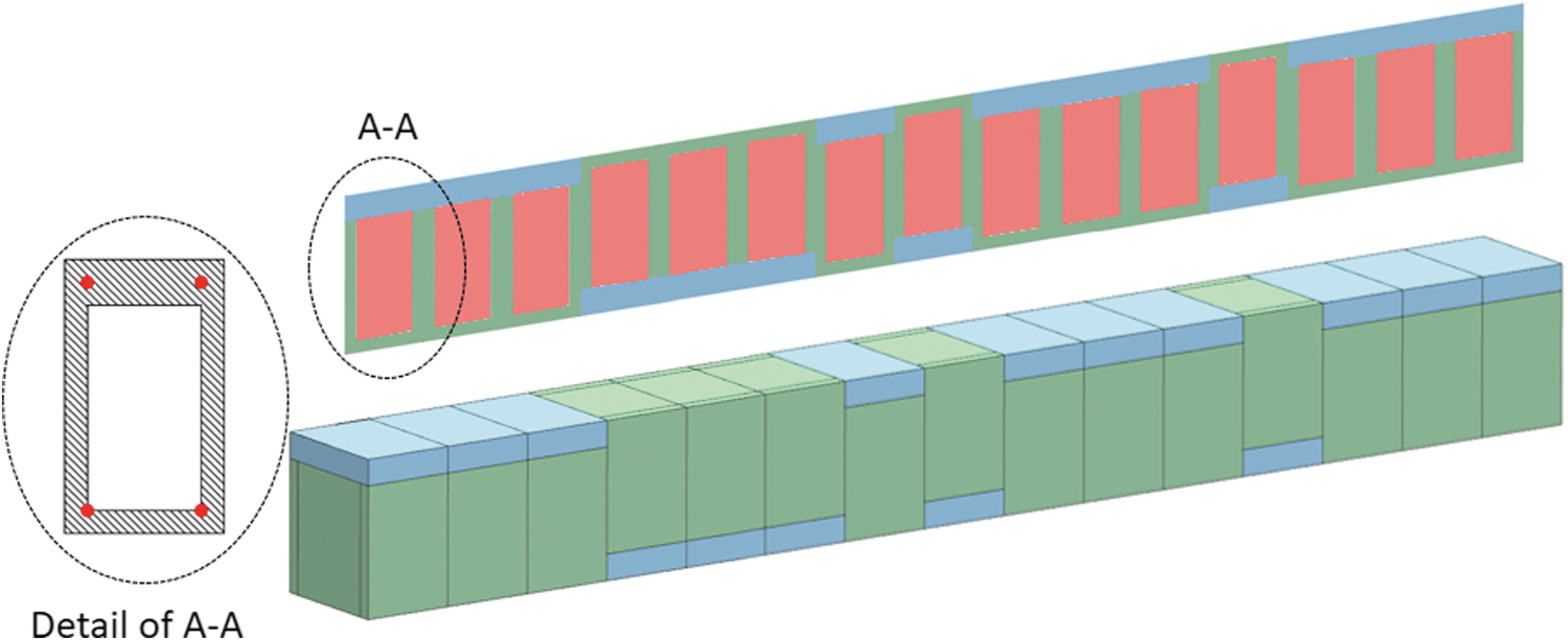
A 2D slice (above) from the center of a 3D CAD model (below) of an actuator. This slice is within the plane that the 3D model can deform in and forms the backbone of the plane-strain reduced order model. The light red rectangles show the region where additional material was added in the 2D model to compensate for the stiffness provided by the sides of the 3D model. The detail insert shows the cross-sectional representation of a modular articulating unit. The four red dots indicate the nodes of which deformation is tracked for further calculations. 2D, two-dimensional; 3D, three-dimensional; CAD, Computer Aided Drafting. Color images are available online.

where Yi is a vector with the superscripts referring to displacements of the desired profile and those of the actual actuator for which its fitness is being calculated and the subscript used to denote each of the increments for which the nonlinear solution is solved. The fitness metric is therefore calculated individually for each solution increment and stored as an array.
Mesh refinement of 3D model
A mesh refinement study was performed on an actuator with all of its units orientated in the same direction. The coarsest possible mesh is where one element is used through thickness, that is, 1.5 mm edge length of a hexahedral element. The mesh was refined by increasing the number of through thickness elements on the thinnest wall section. The meshes investigated therefore had one, two, three, or four hexahedral elements through the thickness with edge lengths of 1.5, 0.75, 0.5, and 0.375 mm, respectively.
These element sizes were evaluated using linear 8-node element formulations and an actuator inflated to 45 kPa using only 8 U, Figure 4. This reduced actuator length was used to allow the models with finer meshes to be solved on a desktop computer in a reasonable time. The 1.5 mm element size was evaluated using a quadratic 20-node element formulation as well. The solution time for each model is presented in Table 1 where models were solved using an Intel i7-4770 CPU at 3.4 GHz.

Mesh refinement of shortened (8 U instead of 15) 3D model using different element sizes and formulations. All units are orientated in the same direction and the actuator is inflated to 45 kPa.
Solution Time During Mesh Refinement
It proved difficult to conduct a quantitative analysis of the performance of each mesh. In this work the overall deformation shape of each actuator is of concern. As such, the analysis will be qualitative. The coarsest mesh with the lowest quantity of nodes solves in the shortest time, but also yields the least deformation. Decreasing the element size delivers more deformation, although at an increased solution time. The mesh appears converged for element sizes less than 0.5 mm, but these require run times in excess of 2 h. A trade-off between accuracy and time is required. The 1.5 mm elements and a 20-node formulation approximate the values of the converged mesh at a much quicker run time. The quadratic 1.5 mm element is thus used for all further work.
The design algorithm only requires displacement values from the numerical simulation as the pressure at which failure occurs was experimentally determined. Strain values from the model are therefore not required. This sole dependence on displacement information allows a computationally cheaper means of accurately approximating it to be investigated, even if it requires certain nonrealistic features. A reduced order model is researched to this end.
Enabling varying pressure
For additional accuracy at matching the desired profile, it was required to utilize a varying pressure in the models in lieu of always using the maximum available pressure. Two different methods exist to achieve this:
Specifying discrete pressure variables and using these as the maximum pressure in the model.
Utilizing the nature of implicit nonlinear FE solvers and the increments in which the models are solved.
Method 1 involves adding extra information to each individual in the population. This information will have to be added to the orientation vector, but will need to act independently thereof. A key between the information in the vector and how that decodes to a pressure magnitude will be required. Individuals will therefore be calculated at different maximum pressures and that value can then be used in calculating the fitness value. This method is computationally more expensive and also very inefficient in the way it utilizes already calculated information.
Method 2 utilizes the converged results for every increment in the FE solver. These increments correspond to increments in the applied pressure loading. For one simulation result it is then possible to extract displacement information at a multitude of intermediate pressures. Preliminary testing proved that the numerical models can be solved using ten increments. Where a smaller step size is required for convergence, numerical cutback is allowed, but these results are not added to the .pch file that is exported. The benefit of this is that a very structured output file is generated irrespective of how many cutbacks were required to solve the model. At no additional computational cost, a more efficient optimization procedure can be run and converged results at different pressures extracted.
Reduced order modeling
The level of detailed information obtained from the 3D numerical models is largely excessive for the purpose of this research and comes at the cost of prolonged run times. Since an iterative approach will be followed as part of the design methodology, it is imperative to reduce the time required for each function evaluation required as part of the fitness evaluation. As such, a means of reducing the 3D model to an equivalent two-dimensional (2D) planar case was investigated and is presented.
The 2D model is a cross-sectional representation of the 3D model, but with an additional linear isotropic material added that fills the void section (seen in Fig. 3) of the 2D model. The stiffness (i.e., elastic modulus) of this filler material is calculated using Design Optimization Tools (DOT) from Vanderplaats Research and Development 38 (a general-purpose gradient-based optimization library) and a custom Python script that matches the 2D displacements to those of the 3D.
The objective function for the optimizer is calculated as the squared nodal displacement error between the 2D and 3D models:

where
An actuator length consisting of 15 modular units was used to calculate the stiffness of the filler material. An optimization procedure was set up to calculate the required stiffness at pneumatic pressure increments of 5 kPa over the range 5–45 kPa. The pressure is equally applied outward to the four edges which forms the void of each unit. For each pressure increment a new random orientation vector was generated and a random initial starting point was used. This complete optimization was run three different times to minimize local minima from skewing the results. Figure 5 shows the results from these different runs along with two different least-squares regression fits used to model the behavior. The R2 value for these two fits is shown in the figure legend, and distinction is made from the different optimization runs using the acronym of the optimizer used—DOT.
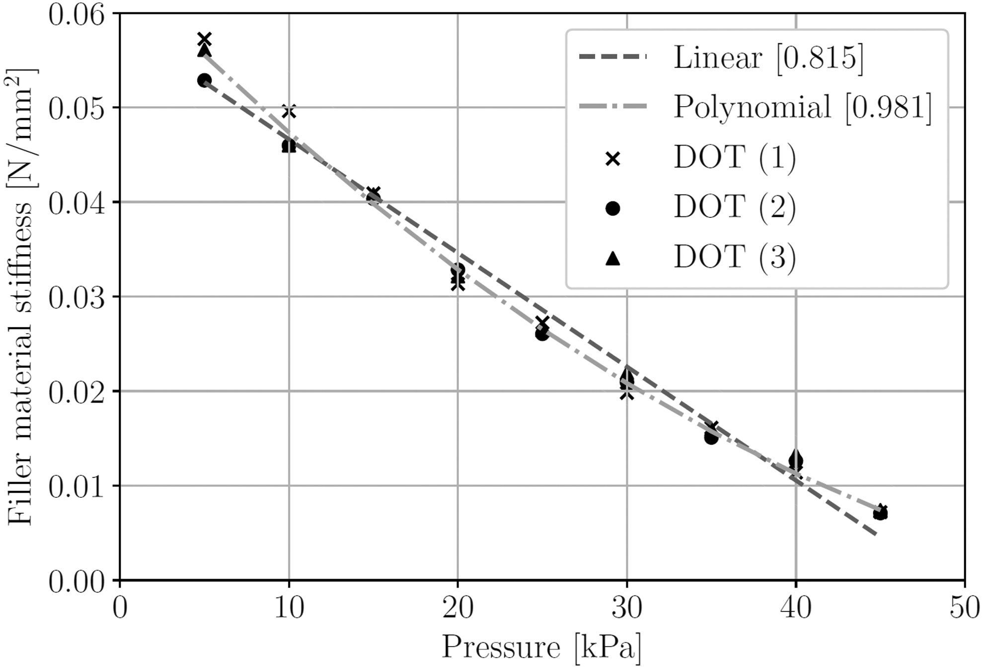
Relationship of filler material stiffness to internal actuator pressure as shown for three independent runs using DOT and random orientation vectors. DOT, design optimization tools.
Results from the three different runs all show a similar trend where required stiffness reduces as the inflation pressure increases. No obvious outliers were converged to. Based on the R2 value, the quadratic fit models the data much better than the linear fit and was therefore the chosen model. There is no extra cost (computationally, or input complexity) involved to implement a quadratic model over that of a simpler linear model in the FE software. This model therefore acts as a smeared response between the three different sets of results calculated and is represented as

with pressure in MPa and E in MPa.
The sensitivity of the reduced order model to changes in this stiffness value was investigated. The 2D simulations were run and displacements calculated at a pressure of 45 kPa using the three different results calculated using the optimizer, as well as the prediction at that pressure using the quadratic model. Investigating the performance of the quadratic model against the 3D model by calculating the distance between similar nodes, the two models vary on average 3.3% along their length. For the random orientation vector investigated, the model does not appear overly sensitive to small changes in the stiffness value of the filler material as small errors are computed. This quadratic representation of the filler material is included as the material property of the 2D unit. The numerical model was adapted to change the stiffness of the filler material as the internally applied pressure load is increased as part of the process when solving a nonlinear FE analysis. A more detailed explanation of the reduced order model, as well as the method used for prescribing a pressure-dependent material property, is included in the Supplementary Data.
Results
Numerical designs
GAs require that a few user inputs be made before running the script. These parameters assist the GA with obtaining the best available solution. With poor user input, the optimizer can prematurely converge to a local minima or can present final answers before an optimum has been reached due to slow convergence and a fixed number of iterations.
Population size and number of generations required were investigated to improve the answers predicted by the GA. At a population size of 80, a converged answer is also found before the 13th generation. The remaining design problems all require that 15 U be used as the actuator length. To further improve the quality of the candidates provided, a population of 100 individuals evolved over 15 generations was used for further design work.
The design algorithm was tasked to solve problems where a single objective was applied to the tip position. To achieve the required outputs, only the position of the tip was considered. The hyperparameter in the GA that determines whether the fitness function must be minimized or maximized was altered as required. These results are shown in Figure 6.

Various design objectives placed on the actuator tip.
The ability of the design algorithm at providing candidates for which the inflated shape best matches a desired continuous profile was tested. Two trigonometric functions, evaluated at various amplitudes, were used for this purpose; sine and cosine. For both functions the design was restricted to investigate one full period and try to match the various amplitudes as best possible. No restriction was placed on the inflated length. Figures 7 and 8 show the results from these optimizations.

Candidates that best fit one period of a cosine function with various amplitudes.

Candidates that best fit one period of a sine function with various amplitudes.
In each of the cases investigated there is deviation between the 2D and 3D models. The inflated shape of the 3D actuator however qualitatively resembles that of the 2D profile. For both the sin and cos functions, candidates are provided that closely match the desired profiles at lower amplitudes. With increasing amplitudes comes larger disparity between the desired profile and what the numerical actuator could achieve. This does not necessarily indicate a weakness in the design algorithm, but points to a physical restriction of the articulating unit at larger deformations. The nature of the two different profiles allows the cosine function to fit to larger amplitudes than the sine function can. The design algorithm successfully managed to present candidates with different orientation vectors to best match the specified objective function.
Physical actuators
A modular mould was designed and machined from billet aluminum. Benefits of this approach include achievable tolerances at ±0.02 mm and a stronger mould that is less susceptible to degradation from continued use. The FDM 3D printers that were available during this research could not deliver the required tolerances to ensure accurate wall thickness of the actuator or to facilitate the smooth assembly of a modular mould with different interacting components. This would require that a unique mould be designed and printed for each actuator leading to increased production turnaround time and cost. The Mold Star 15 prepolymer was poured into the mould and placed in a vacuum chamber for 15 min to enable trapped air bubbles to escape. After complete curing, the actuator was released from the mould and the flashing removed. Circular holes 1.5 mm in diameter were punched between adjacent units to ensure connectivity for air.
The Smooth-Sil section was not cast to the final required dimensions, instead it was cast as one large slab between two glass panes separated with aluminum spacers machined to a thickness of 3 mm. The cured slab was cut into 15 mm wide strips using a sharp blade and a steel ruler. These strips were further cut down to the required individual lengths specific to each actuator. Smooth-On Sil-Poxy was used to glue the different sections together. Figure 9 shows an assortment of the uninflated manufactured actuators.

Assortment of uninflated manufactured actuators. Color images are available online.
The actuator was tested on its side while placed on a lubricated glass pane, such that the plane of deformation and that of the glass were parallel. Silicone oil was used as a lubricant to lower the friction between the actuator and the glass. The effect of gravity on the deformed shape could therefore be minimized. The actuator was inflated by inserting an 18 gauge surgical syringe through the base into the void of the first articulating unit. An additional 18 gauge syringe was inserted for pressure measurements using a 25–500 mbar Endress+Hauser pressure transducer. The pressure was regulated using a Festo manual pneumatic pressure regulator.
Once inflated to the required pressure, a two camera HP 3D Structured Light Scanner was used to scan the deformed actuator. The model was cleaned up using the HP 3D Scan 5. During scanning the pressure was kept at a constant value. As the shape of the actuator was scanned instead of measuring the deformation to a datum it negated the requirement for an accurate boundary condition at the base of the actuator while testing. A schematic of the experimental setup is shown in the Supplementary Data.
It is required to demonstrate how the actuators generated by the design algorithm translate to the real world. A number of selected actuators were therefore manufactured and physically tested to find the correlation between them and the corresponding numerical models. Figure 10 shows these actuators as the physical models overlaid with the perimeter of the numerical models for each actuator.

Comparison between numerical and physical models for various design objectives. The 3D scanned physical model is shown as the background image with the planar results of the numerical model overlaid on it. The numerical results are colored according to the embedded histogram showing the deviation between the two models. The deviation is further quantified using a root mean square error (RMSE) presented in brackets. Color images are available online.
These results were processed using CloudCompare and the point clouds from the scanned actuator and the numerical model. The two clouds were aligned to one another using four unique points and a Cloud-to-Mesh computation performed to calculate the deviations between them. The point clouds are rotated and translated to best match each other, but are not scaled. The Cloud-to-Mesh computation allows the deviations of the numerical model to be displayed using a color grading that corresponds to a histogram of the deviations embedded in Figure 10. A root mean square error (RMSE) was calculated using these data for each actuator tested and is provided in Figure 10.
A quantitative comparison between the performance of the physical models and the numerical models is provided. For all designs presented, the physical models correlate within a RMSE of between 1.76 and 3.80 mm to their corresponding numerical counterparts. These deviations can be seen as the dark blue and bright red areas in Figure 10. In three of the four designs tested the physical model appears overly stiff, with the exception of the cosine function design. The RMSEs are small compared to the uninflated length of the actuator (<2.5%), and the desired design targets can be identified in the inflated physical actuators.
Conclusion
This research set out to develop a computational tool that can assist with designing modular soft robotic actuators where the final inflated shape is of importance. It was shown that it is possible to utilize numerical design and optimization tools for this process. Using a modular approach, and a simple deforming unit, it was possible to allow the design algorithm to predict the orientations for each of the 15 U to best match the desired profile. The employed GA drastically reduced the number of function evaluations required to reach this optimum design from a possible 32,768 available combinations to <1000 function evaluations.
The computationally intensive task of solving hundreds of 3D FE analyses as part of an iterative optimization scheme was investigated to find a solution for improved run times. It was possible to create a reduced order model of the system, where the 3D model that uses quadratic hexahedral elements was simplified to a 2D plane strain case using quadratic quad elements. This model decreased the solution time for each fitness evaluation from ≈590 to ≈45 s, on average, for the actuators investigated. Quantifying the error between the 3D model and the reduced order 2D model using a random orientation vector showed an average node-to-node error along the center line of 3.3%. The results, where the reduced order model was used as part of the optimization, showed larger deviations. The overall deformation shape however remained qualitatively similar and, given the much decreased run times, proved to be a valuable addition to the design algorithm.
Five different physical actuators were manufactured, each designed for a unique prescribed shape. The testing procedure followed made an attempt to measure the most accurate shape of the inflated actuator using a 3D scanner and methods that reduced measurement inaccuracies. A quantitative comparison between the numerical and physical models shows a maximum RMSE as <2.5% of the uninflated actuator length and therefore an overall close correlation between the deformed shapes. The extensive numerical design work performed throughout this work therefore is in agreement with physical actuators.
The final design algorithm is capable of suggesting candidate solutions that closely match a request from a user for a desired profile. The suggested candidate is numerically determined, but also quantitatively resembles that of a physical model.
Footnotes
References
Supplementary Material
Please find the following supplemental material available below.
For Open Access articles published under a Creative Commons License, all supplemental material carries the same license as the article it is associated with.
For non-Open Access articles published, all supplemental material carries a non-exclusive license, and permission requests for re-use of supplemental material or any part of supplemental material shall be sent directly to the copyright owner as specified in the copyright notice associated with the article.