




Abstract
Continuum robot arms, with their hyper-redundant continuously deformable bodies, show great promise in applications deemed impossible for traditional rigid robot arms with discrete links and joints, such as navigating tight corners without getting stuck. However, existing continuum robots suffer from excessive twisting when subjected to offset loading, even resulting from their own body weight, which reduces their dexterity and precision. In this work, we present a continuum manipulator that is capable of providing passive torsional stiffness through an origami-inspired modular design, remedying the non-controllable twist typically present in continuum robots. Our proposed origami continuum module is ∼73 times stronger in torsion compared with similar-size continuum modules made out of silicone rubber, while being 50% lighter, and capable of 125% change in length. Building on these physical capabilities, we present an optimization-based method to solve for the inverse kinematics of our multi-segment origami continuum manipulator that ensures smooth motion to follow desired end-effector paths, minimizing vibrations of the long and slender body. Further, taking advantage of the length-change capabilities of our origami manipulator, we devise and evaluate grow-to-shape algorithms to plan for full-body robot insertion motions that follow tortuous paths. Lastly, we showcase various applications of our proposed continuum robot for pick-and-place, inspection/exploration, and robotic art. Our study presents a highly capable continuum robot for safe manipulation and structure inspection applications, with potential for real-world deployment.
Introduction/Background
Soft robots have recently shown promising results in minimally invasive surgery, 1 rehabilitation, 2 search, and rescue. 3 The potential is attributed to inherent compliance, fault tolerance, and reduced weight. Various capabilities of current soft robots are reviewed in Laschi et al. 4 and Cianchetti et al. 5 However, soft robots are still lacking in terms of precision compared with their rigid robot counterparts, attributed to the nonlinear behavior of their structures or materials.
A significant subset of soft robotics research is focusing on continuum manipulators, inspired by snakes, tentacles, and trunks, to imitate the remarkable capabilities of biological counterparts. A continuum manipulator is generally composed of serially connected sections with infinite passive degrees of freedom, each capable of planar or spatial bending. Recent literature presents continuum manipulators that utilize different actuation methods, including pneumatic,6–10 tendon driven,11–13 shape-memory-alloy,14,15 vacuum, 16 and hybrid. 17 A comprehensive review of continuum robots can be found in Webster III and Jones. 18
Continuum robots capable of extraordinary change in length have been demonstrated in the literature, including OCTOPUS with 41.3%, 14 Air-Octor with 246.2%, 6 and a more recent growing motion modality achieving up to 25,000%. 19 However, it is unclear whether these existing systems are able to resist torsional load, which we identify as a key source of positioning errors for continuum arms. Twist resistance is especially important to mitigate the effect of offset loads since continuum arms do not possess an active degree of freedom in the torsional direction.
Majority of the continuum robots utilize a centralized actuation system, which makes it difficult to add degrees of freedom and limits the great promise of these robots to achieve greater positioning capabilities as compared with a rigid manipulator arm. In contrast, a modular and decentralized approach will enable greater scalability and customization depending on the specific use cases.16,20–22 A modular approach allows for simpler control schemes, as each module can be controlled independently. Further, since the modules are independent and connected together on a communication bus, they can be scaled up to achieve functional redundancy without modification to the overall system architecture, and failed modules can be easily replaced.
Origami, the paper folding art from Japan, has been a source of inspiration for scientists and engineers, ranging from DNA-folding, 23 to foldable solar arrays. 24 Origami enables the construction of complex three-dimensional (3D) objects from a planar sheet. In the field of robotics, origami-inspired design has been shown to offer benefits in creating self-assembled, 25 deployable, 26 adaptable, 27 impact-resistant, and lightweight robots.28,29 A comprehensive review of origami robots can be found in Rus and Tolley. 30 In this work, we present selective compliance in axial and bending directions of an origami-inspired tessellated tubular structure, which provides the required behavior of a continuum module. To be more specific, we can create bellow-like origami structures of different sizes and shapes, capable of facilitating actuation, while also being lightweight and torsionally stiff. Our approach is similar to the work by Vander Hoff et al. 12 and Zhang et al. 13 in that the continuum body is composed of an origami tessellation; however, we focus on engineering the torsional/axial stiffness, robotic operation with electromechanical integration, and modularity of our origami continuum robots. In contrast, it is unclear from these previous works whether the modules can withstand significant torque, and no modularity was presented. To the best of our knowledge, only the work by Qi et al. 11 reported the measure of torsional stiffness for continuum robots. Further, our origami robot utilizes the axial stiffness of the module itself to provide restoring force instead of relying on additional springs. 13
Inverse kinematics formulation is essential to achieve low-level robot motion, to find the necessary joint configurations that will produce a desired pose in task space. The inverse kinematics solution is often nontrivial even for conventional rigid robots, and it is further complicated by the highly nonlinear nature of hyper-redundant continuum robots. In general, there is no closed-form solution and several quantitative and qualitative methods to solve for the multi-section continuum inverse kinematic problem have been recently presented.31–34 However, the solution proposed by Neppalli et al. 31 does not allow for decoupling of the desired tip position and orientation of the robot. Thuruthel et al. proposed using a multi-layer perceptron to develop a global inverse kinematics solution on the position level. 32 This approach would require model retraining for extension of the system and finding appropriate tolerance in training samples. In general, a popular approach is to use accurate forward kinematics models and use an optimization method to solve the inverse kinematics problem.33,34 We follow a similar methodology, and we focus on the effect of cost functions on the precision of the robot pose. In contrast to similar work, we provide a complete solution that accounts for both position and orientation. We show that maximizing the smoothness of the low-level motor commands avoids exciting vibrations of the long and slender soft robotic body and results in more precise positioning performance.
Applications such as minimally invasive surgeries, search and rescue, and structure inspection demand robots to successfully traverse through tortuous paths. Due to their highly redundant and compliant natures, continuum robots promise a suitable solution for this particular requirement. Choset and Henning realized the potential of serpentine robots to navigate through tortuous paths by controlling the continuum robot body to follow the path traced by the head, hence the term follow-the-leader motion was coined. 35 This routine translates to appropriately selecting tube precurvatures and deployment sequences in the context of a concentric tube robot, 36 or finding robot joint configurations that advance its tip to the desired position along the path while minimizing deviation from the path previously traversed,37,38 or even through mechanical design that intrinsically guides the robot to follow its tip motion. 39 Non-extensible continuum robots typically require an additional feed-in/insertion system to achieve follow the leader motion more effectively. In contrast, extensible continuum robots, similar to the one proposed in this article, are more advantageous as they can approximate the path more accurately through contraction to their minimum module lengths (ideally to 0 length) and extending while maintaining constant curvatures. Further, extensible segments provide enhancement in the workspace of the manipulator. 40 In this work, we propose a heuristic method that we term the “grow-to-shape” algorithm and compare its performance with the optimization-based methods described by Palmer et al. 37 and Neumann and Burgner-Kahrs. 38 We extend the heuristic approach with selective optimization and present results in both simulation and experimental results.
Here, we introduce a novel modular continuum robot that is capable of significant deployable extension and high resistance in torsion achieved through origami-inspired design. Second, we propose a smoothness maximization method to solve for inverse kinematics and to achieve task-space control of the robot. We evaluate the performance of our origami continuum robot following the calculated inverse kinematics trajectories with and without feedback control. We also develop a grow-to-shape algorithm to highlight the superior capability of the continuum robot in navigating through tortuous paths. Last, we showcase the robot capabilities in various experimental scenarios by employing the proposed methods.
Methodology
Origami module design and fabrication
The initial step in fabrication of the module is to prepare the compliant origami body by laser cutting the modified Yoshimura origami pattern (Fig. 1) onto 0.178 mm-thin polyethylene terephthalate (PET) film (McMaster Carr). We designed the crease pattern in SolidWorks and exported it to the laser cutter (Epilog, Zing 24) for cutting. The stiffness of the PET film is reduced due to the perforated patterns left from the laser cutter, allowing it to be folded by hand. The origami body is manually folded into an approximate triangular tube and later secured to an acrylic plate (2 mm thick) on the top and a custom-made printed circuit board (PCB) on the bottom. Three actuation cables are then routed along the length of the body through the appropriate channels evenly spaced in radial dimension. They are then attached to spools mounted on the brushed gear motors (secured on the PCB) at one end, and they are fastened with screws and nuts on the acrylic plate at the other end.
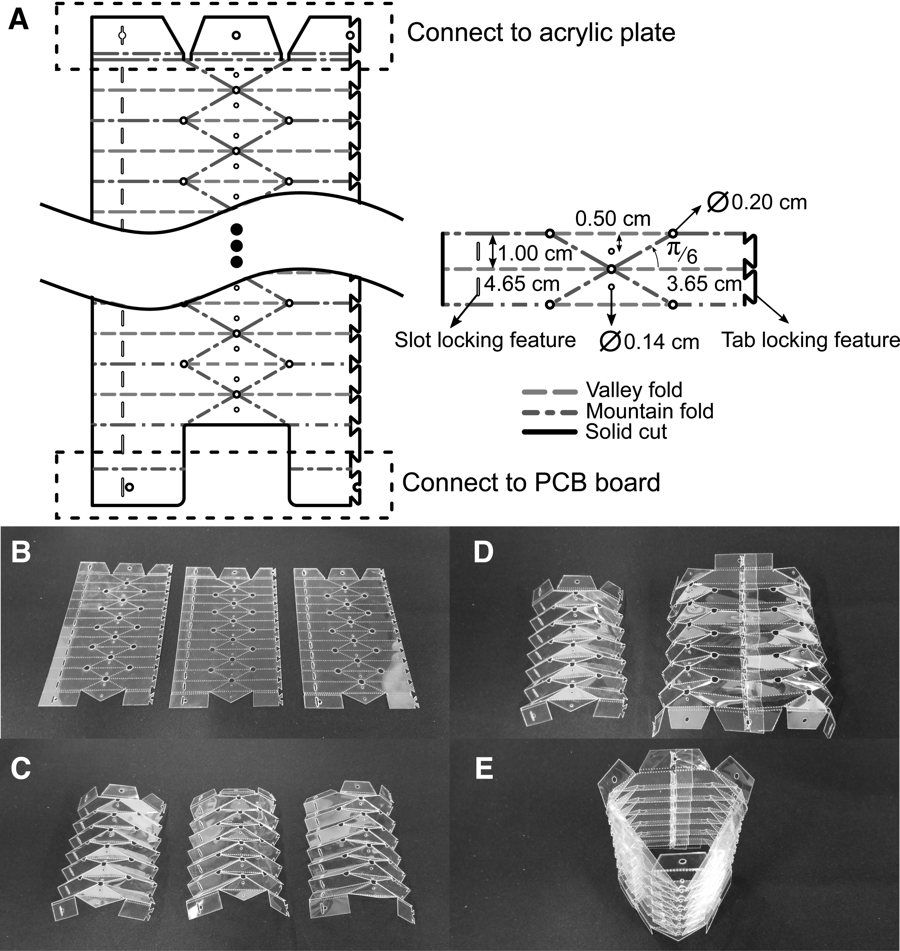
Details on the origami body fabrication.
We designed and assembled a custom-made controller board that contains an 8-bit microcontroller chip (ATmega32U4; Atmel), three motor driver integrated circuits (DRV8801; Texas Instruments), and three encoder quadrature counter-integrated circuits (LS7366R; US Digital). The main task of the control board is to receive appropriate motor commands, estimate the motor positions using encoders, and perform local feedback motion control. An off-the-shelf micro-controller board (Mega 2560; Arduino) is used to interface the module controller boards; an external desktop computer handles inverse kinematics calculations (MATLAB; MathWorks) as well as data collection by the OptiTrack motion tracking system (NaturalPoint, Inc.). The module control boards communicate to the desktop computer by using inter-integrated circuit (I2C) protocol. A total of four electric wires are needed for each origami module for power and I2C communication. The interface between origami modules includes connecting these wires to the appropriate receptacles present on the control board of the proceeding module. In addition, the modules are mechanically secured by using screws.
Origami module characterization
To determine the axial stiffness of the origami compliant body, we fixed one end of the origami body to a motorized linear slide and the other end to a load cell (TAL220; Sparkfun) secured to a table-top vise (Supplementary Fig. S1). The linear stage was used to compress and decompress the origami body at a rate of 7.25 mm/s. For each experiment we repeated the loading cycle for five times and over three different origami bodies. Force readings at 10–80 mm with 10 mm increment are then extracted from the raw data and processed to obtain mean and standard deviation. The axial stiffness is determined by the slope of the graph (Fig. 3A). The same setup is also used to conduct the cyclic loading for 1000 cycles, at which the force and linear displacement data are collected. For each cycle we calculated the axial stiffness by linearly fitting the force-displacement data points.

A similar setup was used to evaluate the torsional stiffness of the origami body (Supplementary Fig. S2) at which the linear slide provided known torsional load. However, for this experiment we connected strings to the top plate of the origami structure at distance of 2.565 cm from the plate's centroid (moment arm). They were then routed appropriately and their ends were tied to the load cell that was mounted to the linear slide as well. The axial force provided by the linear slide was transformed to twisting moment due to the moment arm. We programmed the linear slide to the provided force in the range of 4.45–44.5 N with 4.45 N increment, which corresponds to 0.1141–1.141 Nm. The force range was decided based on the force capability of the linear stage. The amount of twisting (rotational displacement) was measured by using the OptiTrack tracking system. For each module we repeated the experiment three times and we had three modules in total. The same experiment was conducted on a single Silicone actuator up to 0.434 Nm torque. We then extracted the mean and standard deviation of the torsion-angular displacement from the raw data (Fig. 3C). The slope of the curve represents the torsional stiffness of the bodies.
Results
Origami-inspired continuum module
We designed and developed a tendon-driven modular continuum robot that is capable of significant length change (about 1.25 times its original length) and highly resistant in torsion (73 times stronger than a similar size silicone module). These two characteristics are attributed to the tubular accordion-like tessellated origami structure fabricated from a 0.178 mm-thin PET sheet. The PET sheet was chosen as substrate material due to its high strength-to-weight ratio and ready availability. The origami structure was folded following the well-known Yoshimura origami crease pattern as shown in our previous work where we introduced the origami modules. 41
The only predetermined geometric parameters of the crease pattern are the valley-fold length and the sector angle (angle between adjacent creases). The former parameter dictates the radial dimension of the tubular structure. In this case, we selected the smallest dimension that is still able to accommodate all the three motors arranged in an equilateral configuration. The smallest sector angle is chosen to be smaller than 90° to allow for a locally rigidly foldable structure. 42 We did not investigate the effect of varying the geometric parameters of the crease pattern on the performance of the tubular structure. With the current crease pattern design, we can achieve full compression of the structure and linear axial stiffness behavior. It may be beneficial in the future to study the effect of geometric parameters, if any, on the tubular structure performance.
Each origami continuum module consists of a compliant plastic body (Fig. 2A), an acrylic end plate (Fig. 2B), and a custom-made PCB for embedded control (Fig. 2C). For module actuation, we utilize three off-the-shelf brushed micro-gear motors (stall torque of 0.176 Nm) coupled with 3D-printed spools to provide pulling force through the attached tendons. The tensile force is then responsible for generating internal moment, hence shaping the module following a constant curvature arc segment. Position feedback is achieved by using attached encoders on each motor, translating rotational position to a change in tendon length. Restoring force is provided by the origami structure's inherent axial stiffness. We iterated on the module design to reduce its overall profile, for example, radial size and interface between the modules. The current module properties are summarized in Table 1. In contrast to the other continuum robots, our origami module does not have a rigid or flexible backbone and provides restoring forces solely from the origami folds instead of using additional springs or magnet pairs. This allows for a much lighter system. The origami creases provide the restoring forces and this is attributed to the bending stiffness of the material. Further, the modular property of the proposed origami structure allows for scaling of the overall system when necessary. A total of four electrical wires are run through the cavity of the origami structure in a helical shape, providing power and communication between continuum modules.

Physical Properties and Performance of Origami Module
Origami module stiffness characterization
Module characterization is essential to evaluate its range of capabilities and to determine appropriate specifications for the actuation subsystem. The tubular origami structure used in this work has a longer axial dimension to enable greater deployability in insertion tasks, while maintaining the same radial size as in our previous work. 41 We measured 261.25 N/m and 0.448 N·m/deg for the axial and torsional stiffness, as shown in Figure 3A and C. Further, the fatigue resilience of the module was evaluated through axial cyclic loading of 1000 cycles. We observe maximum 3.14% change (Fig. 3B) in the axial stiffness, suggesting that no significant degradation due to plastic deformation is present. To better contrast the torsional stiffness of the origami module to that of a typical soft actuator, we also conducted a torsional loading experiment on a three-chamber bending actuator we developed elsewhere, 43 with a radius of 15.5 mm and fabricated from Ecoflex 0030 silicone rubber from Smooth-On (Fig. 3D). The three-chamber configuration is necessary for the soft module to be able to produce spatial bending. Each small module is only capable of producing axial elongation when pressurized, thus three modules at a minimum are necessary for generating out-of-plane bending. This is analogous to the three-motor configuration of our origami module. Further, the torsional rigidity of the silicone-based actuator depends mostly on the modulus of the material; however, in contrast, the origami module's rigidity is contributed by its unique structure. As shown in Figure 3C, we observe ∼73 times higher torsional stiffness on the origami module compared with its silicone counterpart and 70 times higher (2.71 rad/Nm) stiffness than reported in Qi et al., 11 despite its comparatively low mass. A summary of the origami module's properties is presented in Table 1.
Multi-section inverse kinematics
In our previous work, we have shown that we can control the shape of a single origami continuum module by tracking appropriate tendon lengths. Further, we connected two origami modules in series and commanded them to bend the same amount in opposite directions to follow a circular tip trajectory while keeping the top plate parallel to the ground, only using simple control inputs without solving inverse kinematics. 41 In this work, we generalize the solution for an N-module continuum robot. To the best of our knowledge, there is currently no closed-form solution for the inverse kinematics of a multi-section continuum robot due to its highly redundant nature. Velocity-based and numerical methods have been promising as a solution for inverse kinematics of traditional rigid robots. In terms of the velocity-based approach, one may construct the robot's Jacobian as done in Godage et al., 44 and utilize it to incrementally bring the robot to its desired pose.
A continuum section can be represented as a circular arc in 3D space with its center in the X-Y plane. The proximal point is located at the origin, whereas the distal point is located in 3D space. Each continuum segment can be fully described by three configuration parameters: arc length s, bending angle
Given the full forward kinematics for the n-section continuum robot, we then constructed a damped least-squares Jacobian,
where ep and eo are the
We opted for an optimization-based method to achieve smooth trajectory control due to more freedom available in controlling the behavior of the robot, in addition to tracking the desired path. More importantly, no gain tuning is required, which we found to be a significant contributor to the behavior of simpler damped least-squares gradient descent solutions. Further, we can use constraint functions to ensure that the solutions are within the actuator limits determined experimentally during calibration. We define the specific optimization problem to be solved as:
where C is the cost function, and
The solutions of inverse kinematic solvers from different methods discussed earlier are presented in Figure 4A. Here, we show representations of the tendon lengths of a single continuum module (Fig. 4B) for clear comparison, with each method color coded (Supplementary Fig. S4 for the complete tendon variations). At first glance, we can see that the solutions provided by the gradient descent and the third cost function (minimize step) are smoother than the rest. We focus on achieving smooth cable-length transients, since rapid changes would cause vibrations and reduce precision (Supplementary Movie S1). To further quantify the quality of the solution, we defined smoothness metric as the sum of difference of cable lengths between iteration steps with results shown on the bar chart (Fig. 4C). As seen in this panel, the solution provided by the gradient descent method is the smoothest when stable; however, when the gain is not carefully chosen, the system does become unstable. The third smoothness optimizing cost function outperformed the other cost functions while slightly lagging behind the best-case gradient descent method.

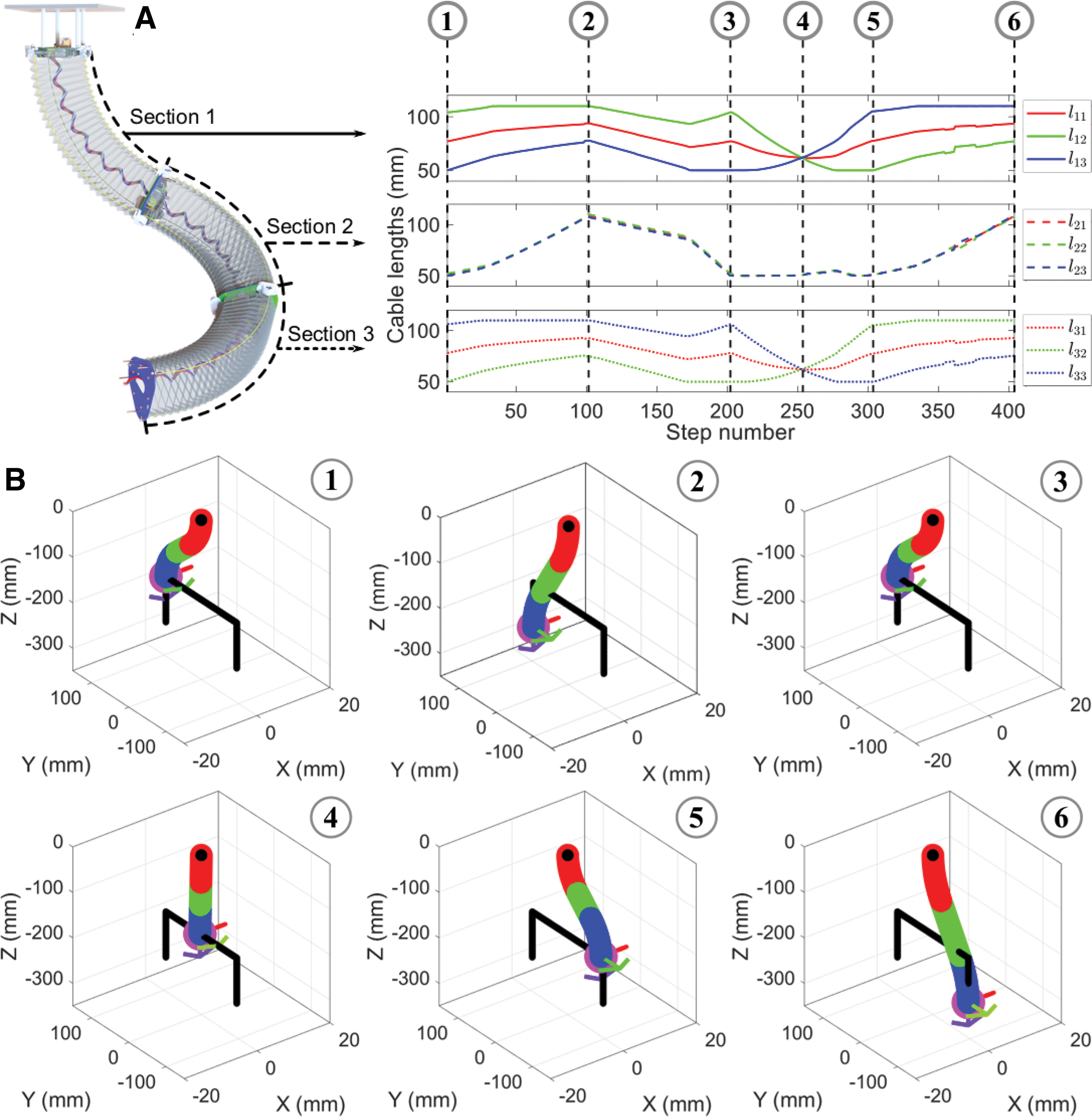
We also evaluated the solving time of the inverse kinematic solvers. For each method we used the solvers to find necessary tendon lengths that will achieve the same tip path. The mean and standard deviation of solving time for 50 repetitions each are summarized in the bar chart (Fig. 4D). The gradient descent method with a suitable damping coefficient performed the best with 0.042 s per step, whereas the gradient descent method with an unsuitable damping coefficient performed the worst with 0.565 s. The second and third cost functions performed similarly, with the former being slightly faster at 0.052 s. Given the similar smoothness and time performance to the gradient descent method minus the instability problem, we selected the third cost function as the final inverse kinematics solver. Figure 5A shows the complete tendon lengths variation over time solved with our proposed inverse kinematics solver. The solution corresponds to a motion of the robot depicted in Figure 5B (simulated in MATLAB) for a pick-and-place application at which the robot descends approaching the object and then transports it to another location while maintaining its orientation parallel to the ground.
Feedback control
Two common approaches to achieve control of robotic systems include model-based and feedback control through sensing. Unfortunately, a perfect model is rarely available and there is a trade-off between model accuracy and complexity. Further, the problem is amplified by the low repeatability of origami-inspired soft actuation modules due to small variations in the manual manufacturing process. In contrast, feedback sensing alone is often insufficient, especially if the sensors are noisy and high feedback gain will tend to make the system unstable. Moreover, a proprioceptive sensing methodology is essential to facilitate the deployment of the robotic system outside the lab environment. Due to the complexity present in the real-world setting, accounting for every single possible interaction between the robot and the environment would be unfeasible. However, an improved robot performance should be observed when a sensing/feedback methodology is introduced, even, to a lower fidelity mathematical model.
In this work, we provide feedback to the robot by using an OptiTrack motion capture system. It is important to note that our long-term goal is to deploy the proposed continuum robot outside the lab; however, the motion capture system was used to illustrate how feedback control could be implemented and be beneficial in reducing positioning errors. On the other hand, it is reasonable to assume that some industrial applications may find ways to use camera systems to monitor the robot motion. We fixed the robot at the base and mounted four infrared-reflective markers to the distal end, allowing us to track the robot end point. The difference between the measured tip pose and the desired pose was then used as the error signal. As traditionally used in robot manipulator control, we multiply the error signal by the robot Jacobian discussed in the previous section to drive the system to zero error in configuration space. Figure 6A shows the evolution of the robot's tip pose without (left) and with (center) feedback. Using feedback, the robot was able to traverse in a straight line while maintaining the top plate parallel to the ground as shown in Figure 6B and Supplementary Movie S2. The feedback is able to reduce the error about 5-fold for position and 2.5-fold for orientation tracking. Moreover, the system converged to steady state within 2 s (Supplementary Fig. S5).

Evolution of the robot's tip position and orientation without and with feedback for multi-pose tracking.
Grow-to-shape algorithm
A significant advantage of the proposed origami continuum arm is its ability to change length, which enables functions that are simply not possible with existing rigid arms. We propose an algorithm we call “grow-to-shape” that will allow the continuum robot to incrementally increase its length while following a certain desired shape and minimizing the deviation from a path, which also becomes the final shape of the robot. Continuum robots with collapsible modules can benefit from smaller deviation in path-following compared with their inextensible counterparts. In this work, we postulate that the continuum robot will grow from the base to the tip module. In addition, the desired robot path consists of constant curvature arcs within the curvature limits of the modules and is predetermined by some other path-planning algorithm. We define the desired robot path/shape to be a set of arc parameters
where
As an alternative to the optimization-based method, we also devised a heuristic approach, with which we command the module transitioning from one segment to the other by linearly interpolating the arc parameters of the two neighboring desired segments (Appendix A2 for details). While not transitioning, the continuum module will trace the arc parameters of the desired segment, which the module is currently in.
We investigated the effect of reducing the initial (minimum) continuum module length on the tip error, which simulates the limit of the origami module's compressed length. As expected, the tip error for the arc-interpolant/heuristic method decreases for shorter initial module length as shown in Figure 7A. In fact, the error appears to converge to the tip error obtained by using the optimization method (which yields almost perfect tracking with an error of about 0.0041 mm). This suggests that the heuristic method will work as well as the optimization approach for continuum robots that are capable of collapsing to 0 mm length (e.g., concentric tubes with insertion rail). We also investigated the effect of increasing the desired arc segment lengths while keeping the initial module length constant. A similar trend of decrease in tip error can be observed, although with a less pronounced effect (about 2.06 mm decrease in error).

Error analysis on the effect of decreasing the minimum module length and increasing the desired segment length independently.
While experimenting with the two previously discussed methods, we realized that a “selective optimization” only for modules that are transitioning between the desired segments may prove to be sufficient. However, this still requires that the desired arc segments will consist of circular arcs with constant curvature. For more general and complex curves, one may need to convert them first into constant curvature segments by using some distance metrics. Further, the selective optimization only makes sense if the desired segment length is longer than the combined initial length of the modules; otherwise, a full optimization is necessary. Figure 7A shows that the selective optimization method outperforms the heuristic method (about 50% lower error) while still having lower performance than the full optimization method. The error decreases as the desired-segment-lengths increase. Although the work done in Neumann and Burgner-Kahrs does not provide a solving time measurement, 38 we collected the solver time per step for each method for comparison (Fig. 7A). The full optimization method has the least error but requires the most time due to the redefinition of the cost function at every time step. By doing the selective optimization we can speed up the solver time about 12-fold, but there is only a small improvement in the tip error compared with the heuristic approach, which runs much faster.
Figure 7B–D shows the experimental results of the grow-to-shape algorithm implemented on the three-segment origami continuum robot for the full optimization and heuristic methods, respectively. We plotted the tracked robot tip position (P3) as the robot grew to the desired “invertedS” shape in the X-Z plane (Fig. 7B and Supplementary Movie S3). Further, we also tracked the tip position of two proximal segments (P1, P2) to help illustrate the overall shape of the continuum robot as it grows. The arc parameters for the final shape are
Origami continuum robot capabilities
We validate possible applications of our origami continuum robot to achieve manipulation and exploration/inspection tasks, which utilize the smoothness-optimization-based inverse kinematics solver and grow-to-shape algorithm. One potential application of continuum robots for manipulation task is to complete a pick-and-place routine. Despite possibly having much lower accuracy compared with traditional rigid manipulators, continuum robots could be beneficial for applications where human-robot synergy is necessary, for example, collaborative assembly or packaging. In this article, we showed that our continuum robot is capable of transferring a 0.5 kg object (Fig. 8A and Supplementary Movie S4). The robot is equipped with a small vacuum-driven suction cup at the distal end and follows a trajectory similar to the one discussed for the pick-and-place simulation results. We observed deviation of the modules from constant curvature arcs due to the external load. This problem could be mitigated by introducing sensors that can detect non-constant curvature shapes for feedback control; however, this is beyond the scope of this article.

Snapshots showing capabilities of the continuum robot:
Figure 8B–D (Supplementary Movie S5) highlights the exploration/inspection applications of our continuum robot in which it “grows to shape” traversing through tortuous paths. The robot successfully navigated through mock walls with holes (Fig. 8B, C) and a maze (Fig. 8D). We introduced translational motion by using a linear stage at the base of the continuum robot to simulate insertion routine typically done in minimally invasive surgeries. It is important to note that we could achieve the same effect by using an additional origami module at the base. Last, we attached a blue light-emitting diode (LED) to the robot's end effector and captured a long-exposure photography of it tracing the WPI letters by using the maximum smoothness inverse kinematics solver as shown in Figure 8E and Supplementary Movie S6. The green letters are conveniently generated from the LEDs of the embedded motor encoders at the end of each module.
Conclusion
The proposed origami-inspired continuum robot offers significant length change and is highly resistant in torsion while having minimal weight. A high torsional strength is beneficial to resist offset loads, which would reduce positioning accuracy even under the weight of the robot itself. Lower mass is favorable to mitigate the sagging problem typically present in continuum robots. Further, lighter mass contributes to a lower inertia, which yields a more stable and safer system. We observed small variations in the modules' axial and torsional stiffness values, suggesting good reproducibility. Further, the cyclic loading experiment illustrates the origami module's durability, although more rigorous testing in the range of hundred thousand cycles may be necessary.
The modular property of our robot allows for easy scalability. To increase its workspace, one may connect additional shorter modules in series or introduce a longer origami body for each module while keeping the same number of modules. However, stronger motors may be required as the moment arms increase as the body gets longer. In contrast to other continuum robots in which the actuators are kept at the base, the distributed actuators of our robot allow for easy replacement of the broken modules. Further, electric-powered actuation provides a potential for the deployment of our soft robot outside the lab environment.
The optimization-based inverse kinematics solver presented in this work allows for control of a multi-section continuum robot. The proposed method shows similar performance to the damped least-squares gradient descent approach in terms of the solving time and smoothness of the cable-length (and hence robot tip) trajectories. Further, the optimization method eliminates the need to tune the damping coefficient required by the gradient descent approach. The development of the inverse kinematics solver is the first step toward the possibility of a wide variety of robotic applications requiring path-tracing capability. However, for time- and force-sensitive applications an inverse dynamics solver could be more appropriate.
We have shown the benefit of introducing feedback into the control of our robot. The initial solutions provided by the inverse kinematics solver allow for a more stable system, as the output of the system is already very close to the desired one. The feedback term was then used to compensate the remaining error not captured by the model. The results show that the performance of the robot was greatly improved through the addition of the motion tracking system. However, a visual-based motion tracking system tends to suffer from occlusion problems and is inherently dependent on an established system of localized cameras. A more ideal solution would be to develop proprioceptive shape sensing that would allow for a fully deployable robotic platform.
Grow-to-shape highlights the main benefit of a collapsible continuum manipulator compared with traditional rigid robots, which allows for navigation through tortuous paths that are typically present in search and rescue, medical, and inspection applications. We have shown that our robot is capable of growing to the desired shape by executing joint configurations given by the developed algorithms. We observed insignificant differences between the experimental data obtained with both full optimization and heuristic methods, which is in agreement with the simulation results. We did not conduct an experiment by using the selective optimization method, as our modules in their current state are not capable of extending three times their minimum length (necessary for the selective optimization method) at the desired curvature value.
We have also showcased the capability of the robot in various validation scenarios. Even though in this article we focused mostly on the application of the origami continuum robot as a manipulator, the bending modules themselves are not limited only to manipulator use cases. Due to their versatility, we envision the modules could be used for bio-inspired robotic applications such as snake, worm, and flexible appendages. In fact, a hybrid robot that is capable of both locomotion and manipulation tasks does not seem to be far-fetched. One can imagine a snake robot that is capable of latching itself onto a structure and transforming into a manipulator.
We identify the following additional works that are necessary before the proposed continuum robot can be reliably deployed to complex environments: development and implementation of a proprioceptive sensor, improvement of the continuum module to include an independent power source and wireless communication, an extension on the control modeling to include the robot's dynamics, and incorporation of controllable stiffness for the origami module.
The feedback control presented in this work utilizes an external optical tracking system that is not always available outside a lab environment. Further, a visual-based motion tracking system tends to suffer from occlusion problems; thus, there is a need for a proprioceptive sensor. Specifically, the proprioceptive sensor needs to accommodate significant deformation (change in length) that our proposed continuum robot is capable of.
Second, the continuum robot proposed in this work still utilizes a centralized power system and a wired communication bus. An independent power source in the form of a battery and a wireless communication device for each module will further improve the modularity of the proposed robot. The improved modularity will result in a deployable system that is more robust against multiple modes of failure.
Implementation of dynamic control would be the natural extension in achieving predictable robot behavior. Further, for time- and force-sensitive applications, an inverse dynamics solver would be more appropriate. However, dynamic control would necessitate a methodology to reliably estimate the torques and forces applied by the robot. In our case, this may involve the electrical current measurement of the motors. The use of brushed motors and gearboxes for actuation makes it difficult to achieve a clean and reliable measurement of motor current. In contrast, the use of brushless motors allows for a better current measurement but they require more complex driver circuitry and control signals.
Last, the origami module's compliant behavior under compression could be considered as a double-edged sword. On the one hand, the inherent compliance allows for constantly safe interaction between the robot and its environment; on the other hand, the compliance also restricts manipulation tasks that require pushing action from the robot. A more robust solution would allow for controllable stiffness.
Footnotes

References
Supplementary Material
Please find the following supplemental material available below.
For Open Access articles published under a Creative Commons License, all supplemental material carries the same license as the article it is associated with.
For non-Open Access articles published, all supplemental material carries a non-exclusive license, and permission requests for re-use of supplemental material or any part of supplemental material shall be sent directly to the copyright owner as specified in the copyright notice associated with the article.
