




Abstract
Programmable materials have artificially designed physical shapes responding to external stimuli, as well as high design capability and high flexibility. Here, we propose a microfiber-shaped programmable material with an axial pattern of stimuli-responsive (SR) and nonresponsive hydrogels. The SR pre-gel solution was mixed to sodium alginate pre-gel solution for instantaneous gelation with ionic crosslinking and solidified on a nonresponsive hydrogel microfiber with a valve-controlled microfluidic system. A design of microfiber-shaped programmable material (patterned position of SR regions) could be flexibly altered by changing a coded sequence program. We confirmed that the three-dimensional (3D) coil-like structures were self-folded at the patterned SR regions responding to the thermal stimulus and that the chirality of the self-folded 3D coil-like structures depends on the condition of the stimulus to the microfiber. Finally, interaction with objects using the programmable microfiber as a soft actuator was demonstrated. Our microfiber-shaped programmable materials expand possibilities of fiber-based materials in biomimetics and soft robotics fields.
Introduction
Programmable materials that are artificially designed in terms of their physical shapes or functions responding to external stimuli have been recognized as key elements to create autonomous microsystems, 1 self-assembling robotics, 2 and active matters. 3 The definition of programmable materials encompasses a wide range, including designed molecules such as DNA, 4 mesoscale structures of functional polymers,3,5 and large-scale machines and architectures.6,7 Among them, microscale programmable materials composed of hydrogels 8 have been attracting attention as programmable biomaterials, because they are made of polymer networks containing water and have extensive design capability, high flexibility, and biocompatibility. Generally, programmable hydrogels have stimuli responsivity,9–11 where the shrinking and swelling behavior of the hydrogels can be triggered by various stimuli (temperature, pH, optics, chemical substances, etc.). These hydrogels are expected to be applied in soft actuators and biomedical sensors.
In addition to the material characteristics of these programmable hydrogels, their geometrical shapes are important factors in determining the functions of programmable materials. Using various shapes such as fibers, 12 sheets, 13 and spheres, 2 fiber-shaped programmable materials are promising candidates for mimicking fiber-based materials observed in nature. For example, vorticella and protein/DNA secondary structures made of folded chains of amino acids and nucleic acids, respectively, have attractive functions owing to their axially programmed structures and motions that respond to external stimuli. These axially programmed fiber-based systems could be used in microscale mechanical systems by adding programmable functions to artificial microfibers. As for engineered hydrogel microfibers, axially anisotropic microfibers that could be applied in microfibers with encapsulated multicellular spheroids have been reported.14,15 However, fiber-shaped axially programmable hydrogel materials that have stimuli responsivity have not been demonstrated.
Objective
Here, we propose a microfiber-shaped programmable material with axial patterns of stimuli-responsive (SR) and nonresponsive hydrogels (Fig. 1a). This programmable microfiber is fabricated by a valve-controlled microfluidic device based on that of a previous study. 14 The programmed pattern of SR regions on the microfiber enables the fiber to locally bend by stimuli exposed over the entire microfiber (Fig. 1b). The bending position on the microfiber can be designed with a coded sequence of open/close motions of the valve controlled by a computer. In this study, the axial patterning accuracy and the microfiber's stimuli responsivity are evaluated. Finally, we demonstrate the programmable deformation of axial patterning microfibers in response to applied stimuli.

Concept of our microfiber-shaped programmable hydrogel materials.
Materials and Methods
Materials
pNIPAAm-co-AAc (acrylic acid 15 mol%) (741930) was purchased from Sigma Aldrich. Na-Alginate (194-13321) and CaCl2 (038-24985) were purchased from Fujifilm Wako Pure Chemical. Fluorescent beads (F8810 [red] and F8811 [yellow-green]) were purchased from Life Technologies.
Valve-controlled microfluidic device
The valve-controlled microfluidic device consists of two layers (Supplementary Fig. S1a). These two layers were produced by using acrylic and poly(dimethylsiloxane) (PDMS) molds in three steps (Supplementary Fig. S1b). In the first step, acrylic molds were fabricated with machine tools (MM100) (Supplementary Figs. S2–S4). We used the acrylic molds for the upper PDMS layer (an upper unit) and the other acrylic molds for the lower PDMS layer (a lower unit and an air valve's unit) to obtain the second PDMS molds. In the second step, we obtained an upper layer and a lower layer cast that were created from the second PDMS molds. In the third step, we obtained the valve-controlled microfluidic device after bonding these layers (microchannel diameter of 0.30–0.60 mm, thin-membrane pneumatic valve diameter of 0.90 mm, and thickness of 100 μm). This device was connected to a syringe pump (Legato 180) and solenoid valves (S070A-5DG) to control the injection of solutions, and the solenoid valves were controlled programmatically by MATLAB.
Types of microfibers
We fabricated two types of microfibers. The first type did not contain SR regions. Conditions: Two differently labeled types of nonresponsive pre-gel solution [1.5 wt% NaAlg(aq)] that contained 5 wt% fluorescent green and red beads, respectively, were prepared. Both labeled pre-gel solutions were introduced into the microfluidic device at the same pressure of 0.06 MPa, patterned with the controlled thin-membrane pneumatic valves (0.12 MPa). The patterned pre-gel solution was solidified with a flow of CaCl2(aq) (flow rate of 50 μL/s). The microfibers were collected by extruding them to the CaCl2 solution pool.
The second type of microfiber contained SR regions and nonresponsive regions. Conditions: The pre-gel solutions consisted of 1.5 wt% NaAlg(aq) containing 1 wt% florescent red microbeads (nonresponsive) at a mixture of 6:1, 3 wt% poly(N-Isopropylacrylamide-co-acrylic acid) (pNIPAAm-co-AAc), and 3 wt% sodium alginate (Na-Alginate) containing 1 wt% florescent green microbeads (SR). Both labeled pre-gel solutions were introduced into the microfluidic device at a pressure of 0.08 MPa (nonresponsive sols) and 0.10 MPa (SR sols), patterned with the controlled thin-membrane pneumatic valve (0.18 MPa). The patterned pre-gel solution was solidified with a flow of CaCl2(aq) (flow rate of 80 μL/s). The microfibers were collected in the same way as the previous microfibers.
Observation method and measurement apparatus for self-folding of microfiber with thermal stimuli
All fluorescent images were captured by an Olympus IX73 inverted microscope or Olympus FV3000 confocal microscope. To measure the curvature radii, the Olympus platform cellSens was used. In addition, the heating thermal stimulus was applied by dipping the microfibers uniformly or sequentially into a hot water bath or putting them on a hot plate. The cooling thermal stimulus was applied by putting microfibers into a refrigerator. These procedures were repeated to measure the cyclic curvature radii. To measure the length or fluorescent intensity of the microfibers, the RGB profile plot of ImageJ was used.
Interaction with objects using programmable microfiber
Based on the previously reported method, 12 the programmable SR microfiber (SR region: tgreen = 500 ms, interval: 100 ms) was cut and fixed between the two parallel tubes, a thin perfluoroalkoxy alkanes (PFA) (inner diameter [ID]: 0.1 mm, outer diameter [OD]: 0.3 mm; 1037-01, ARAM Corporation) tube and a glass tube (ID: 0.6 mm, OD: 1.0 mm, G1, Narishige), in 1 M CaCl2 solution. The position of both the tubes was precisely controlled with micromanipulators. The length of the PFA tube from the manipulator to the microfiber, LPFA, was 41 mm. The initial distance between the fixing points of the microfiber to the two tubes, d, was 41 mm. Thermal stimulus was applied by heating the microfiber in the CaCl2 solution with a hotplate to 50°C. During the heating, the behavior of the microfiber was recorded by a video camera (Tough TG-5; Olympus) with a handy UV light (375 nm). The obtained movie was analyzed with movie analysis software (VW-H2MA; Keyence). By assuming that the stiffness of the glass tube was sufficiently large to ignore its deformation, the pulling force, F, generated by the deformation of the microfiber can be expressed as F = kΔd, where k is the spring constant of the PFA tube, and Δd is the displacement of the fixing points of the microfiber on the PFA tube. The spring constant, k, was calculated with simple mechanics of materials for a tube as, 3EI/LPFA 3 = 0.064 N/m, where E is the Young's modulus for PFA, 30 MPa, and I is the moment of inertia of area for the PFA tube.
Results
We used a valve-controlled microfluidic device to fabricate axially patterned microfibers. The microfluidic device has two microchannels for multiple pre-gel solutions and another microchannel for a crosslinking agent. In addition to these fluidic microchannels, the device has two pneumatic valves with thin membranes that are controlled by applying air pressure, programmed in a PC, through the other two microchannels (Fig. 2a). These valves are key elements to pattern two different materials in the axial direction of the microfiber, enabling us to fabricate axially programmable fiber-shaped materials that are different from the ones formed with a valveless microfluidic system. 16 An image of the actual valve-controlled microfluidic device is shown in Figure 2b, and the motion of the pneumatic valves that were installed to open/close the microchannels for the pre-gel solutions is shown in Figure 2c. The pre-gel solutions were pumped by air pressure (0.06–0.10 MPa). Control of the on/off pumping of pre-gel solutions and the opening/closing of the pneumatic valves (0.12–0.18 MPa) were programmed in simultaneous sequence (Fig. 2d). As a result, two types of pre-gel solutions were sequentially injected into the device. Then, the programmed flow of the pre-gel solutions was passed through the first merging point and converged at the following channel to form the flow of patterned multiple pre-gel solutions. Finally, the patterned flow merged at the second merging point with the crosslinking agent CaCl2 solution (flow rate: 50–80 μL/s) to solidify the pre-gel solution. Consequently, we obtained axially patterned hydrogel microfibers (Fig. 2e).

Fabrication of microfiber-shaped programmable materials.
Successful formation of axially patterned microfibers depends on the performance of the microfluidic device with regard to characteristics such as the pumping intervals (on/off) of pre-gel solutions and the opening/closing of thin-membrane pneumatic valves. To evaluate the accuracy of the axial patterns, we measured the length of the axial patterns, lP, of the materials generated by the valve control of the microfluidic device (Fig. 3a, b). Then, we prepared two differently labeled types of nonresponsive pre-gel solution [1.5 wt% NaAlg(aq)] that contained 5 wt% florescent green and red beads, respectively. Various switching intervals (tgreen = 20–100 ms) were tested (Fig. 3c, d). A fluorescent microscopic observation showed that the labeled materials were axially patterned on the microfibers under the three conditions. We confirmed that the length of the axial patterns (lP) increased by extending the switching intervals (tgreen) when tgreen was greater than 20 ms (minimum length of axial patterns: 2.3 mm) (Fig. 3e). Under tgreen = 10 ms, axially patterned microfibers could not be fabricated. Instead, double-layered microfibers were formed (Fig. 3f).
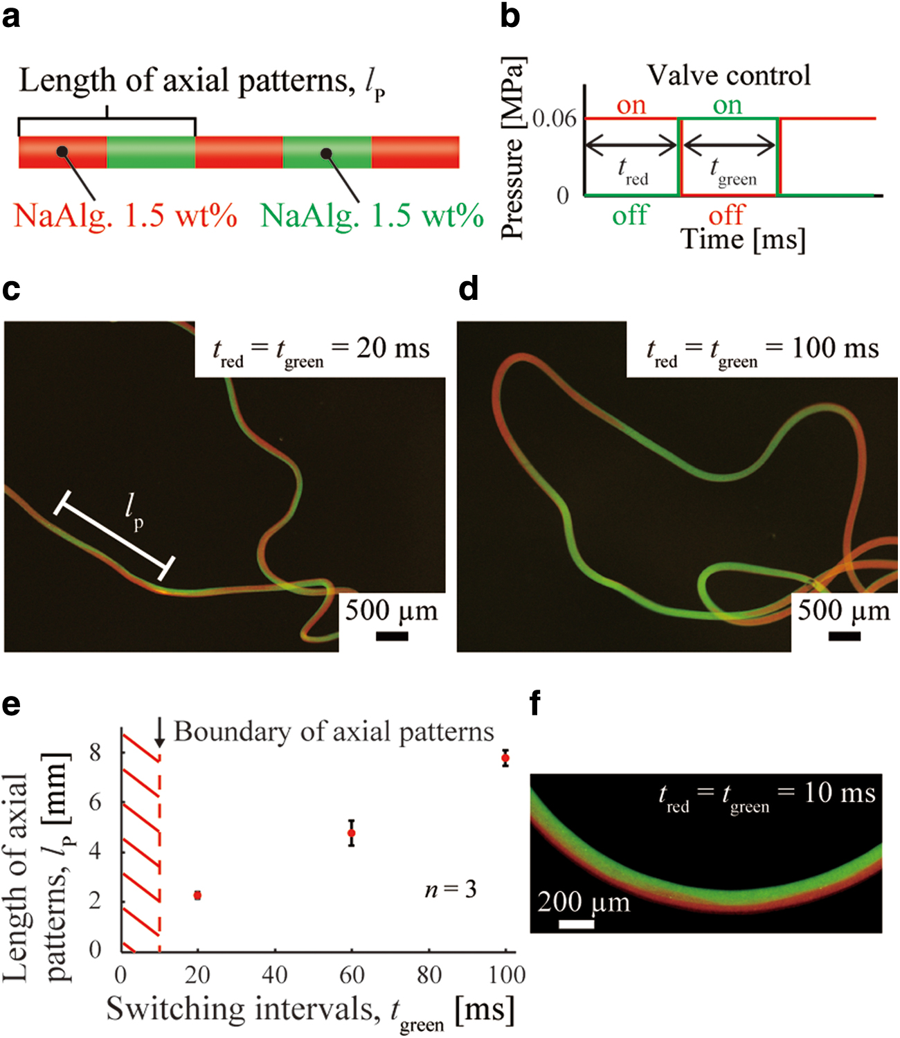
Evaluation of axial patterning with differently labeled nonresponsive hydrogels.
Next, we fabricated axially patterned microfibers having SR regions and nonresponsive regions. A programmable sequence was designed to pattern the SR materials axially on the nonresponsive hydrogel microfibers. To evaluate the accuracy of the axial patterns, we measured the length of the SR region, lSR, of the SR materials generated by the valve control of the microfluidic device (Fig. 4a, b). The pre-gel solutions that we used were 1.5 wt% NaAlg(aq) containing 1 wt% florescent red microbeads (nonresponsive), and a mixture of 3 wt% (poly(N-Isopropylacrylamide-co-acrylic acid) (pNIPAAm-co-AAc) and 3 wt% sodium alginate (Na-Alginate) containing 1 wt% fluorescent green microbeads (SR) at a 6:1 ratio. Three different switching intervals (tgreen = 30, 60, and 90 ms) were tested. Axial patterns on the microfibers were confirmed under all three conditions (Fig. 4c). In addition, we confirmed that the length of the SR region (lSR) increased by extending the switching intervals (tgreen) (Fig. 4e).

Evaluation of axial patterning with SR and nonresponsive hydrogels.
Finally, we evaluated the cross-sectional proportion of patterned SR gel in a single region on the microfiber. Reconstructed confocal images of the cross-section show that the proportion of green-labeled SR gel became larger as the axial distance from the beginning of the patterned region, xSR, increased (Fig. 5a–c). The measurement of the cross-sectional area of the SR gel (ASR) in the total cross-sectional area (Atotal) showed that ASR/Atotal started increasing at xSR = 0 and entered the steady state as xSR increased (Fig. 5d). This result indicates that xSR = ∼1.5 mm was required to achieve stable axial patterns, which corresponds to a 20-ms valve motion from the beginning.

Evaluation of cross-sectional proportion of patterned SR gel.
We then confirmed the responsivity and repeatability of axially patterned SR microfibers by applying thermal stimuli (heating [40°C] and cooling [20°C]) for five cycles (Fig. 6a, b). Then, the ratio of the curvature radii, Rinitial/Rn, where 1/Rn and 1/Rinitial are the curvature radius at n cycles and the initial curvature radius, respectively, was measured in the SR region of the fabricated microfibers. The result showed that only the SR region deformed significantly (maximum |Rinitial −Rn|/Rn = 0.42) owing to the double-layered design of the green-labeled SR pNIPAAm-co-AAc/Ca-Alginate and red-labeled nonresponsive Ca-Alginate (Fig. 6c). These results indicate that microfibers can be deformed locally and repeatedly owing to axially patterned SR materials that respond to external stimuli.

Responsivity and repeatability of axially patterned SR microfibers.
Then, we applied this technology to fabricate a fiber-shaped programmable material with an axial pattern of SR regions and nonresponsive regions. First, we created a sequence program to code a cycle of tgreen = 90, 30, and 60 ms with an interval of 100 ms (Fig. 7a) and obtained a microfiber where three different lengths of SR regions were installed (Fig. 7b). We then applied a thermal stimulus to the microfiber. As a result, the SR regions formed three-dimensional (3D) coil-shaped structures having different turns (Fig. 7c). The angle of the curvatures depended on the length of the patterned region (Fig. 7d). The reconstructed confocal microscopic images confirmed 3D structures of tgreen = 60 and 90 ms (Fig. 7e, f). From this result, we observe that the difference in the number of turns can be controlled by changing the coded sequence program.

Deformation of microfiber-shaped programmable materials.
Next, using our programmable microfibers, we demonstrated a 3D packing of a long microfiber. This 3D packing phenomenon of long microfiber-shaped material can be observed in nature, especially in macromolecules, including proteins. 17 A microfiber having three SR regions (tgreen = 500 ms) was fabricated according to our sequence program (Fig. 8a, b), and a thermal stimulus was applied. As shown in Figure 8c, SR regions formed continuous coil-like structures, resulting in a packing of the 123-mm-long microfiber into a 45-mm-long structure having three independent 3D-packed regions.

3D packing of a long microfiber.
Interestingly, the chirality of 3D-packed coil-like structures depends on how the stimulus is applied to the microfiber. In condition 1, we applied a thermal stimulus to the microfiber uniformly by warming to 50°C with a hot plate to keeping the microfiber in the solution before and after the heating procedure, and all of the SR regions folded at the same time (Fig. 9a; Supplementary Movie S1). On the other hand, in condition 2, we dipped the microfiber in a heated calcium chloride solution at 50°C, and the folding occurred in sequence (Fig. 9b; Supplementary Movie S2). In condition 1, left-handed (LH) and right-handed (RH) helixes were mixed in the 3D coil-like structures (Fig. 9c). By contrast, in condition 2, only one type of helix (LH) existed in the microfiber (Fig. 9d). This difference results from the ease of twisting both ends of the microfiber: In condition 1, neither end of the microfiber could be moved or twisted, largely owing to the constraint of both ends. In condition 2, the microfiber could be moved or twisted because there was no constraint on one end of the microfiber. This phenomenon can be also observed in nature, especially in the growing steps of tendrils. 18 Tendrils grow in different directions depending the constraint conditions of both ends. Our result shows that a similar self-folding phenomenon can occur in our microfibers. Such different deformation behaviors show that our hydrogel microfiber has the capability to precisely sense the stimuli from the surrounding environment, including its spatial gradient: This type of deformation could not be demonstrated previously by printing-based SR structures.19,20

Chirality of 3D-packed coil-like structures.
Finally, for application to soft robotics, interaction with objects using our programmable microfibers was demonstrated as an example of a contractile actuator. We built a setup where a programmable SR microfiber (SR region: tgreen = 500 ms, interval: 100 ms) was fixed between the two parallel tubes, a thin flexible PFA tube (ID: 0.1 mm, OD: 0.3 mm) and a thick rigid glass capillary tube (ID: 0.6 mm, OD: 1.0 mm), in CaCl2 solution (Fig. 10a). The fixed microfiber had SR and non-SR regions between the tubes (Fig. 10b). By applying thermal stimulus at 50°C, the SR region in the microfiber deformed to helical shape to shorten the distance between both the fixed edges of the microfiber. As a result, the thin flexible PFA tube was successfully pulled by the microfiber deformation (Fig. 10c; Supplementary Movie S3). Interestingly, both RH and LH helical structures were observed on the microfiber (Fig. 10c), which was a similar phenomenon to our microfiber deformation experiment at condition 1 (Fig. 9a, c) that could regard both ends of the microfiber as constrained. The time transient of the distance between the fixing points of the microfiber (distance of A–B in the Fig. 10b, c), d, shows that although the value of d was at constant until ∼300 s, it gradually decreased from 41 to 38.5 mm after ∼300 s (Fig. 10d). This delay of the beginning of decrease in d means that the programmable microfiber that was loosely fixed to the tube became tightened to start pulling the PFA tube at ∼300 s. In addition, the displacement, Δd, provided us the value of pulling force generated by the helical deformation of the programmable microfiber: We estimated the pulling force was ∼160 μN by the mechanical characteristics of the PFA tube (calculation was described in the Materials and Method section). This demonstration of interacting with objects shows the potential application of our programmable fiber-shaped material to a soft actuator enabling axial-direction motion.

Interaction with objects using a programmable microfiber as an actuator.
Discussion
We proposed a method to fabricate a 3D-structured programmable material by self-foldable microfibers. The unique characteristic of our method is as follows: By installing SR materials in microfibers axially according to computer-programmed patterns, the designed microfibers can be intentionally self-folded to respond to temperature. In addition, the coil-shaped structure depended on how a thermal stimulus was applied, and the thermal stimulus could be applied simply by changing the experimental environment.
With regard to the shapes of programmable materials, sheet-shaped programmable materials have already been researched. 3 Further, four-dimensional (4D) printing technology to fabricate programmable materials has already been reported.19,21 As for fiber-shaped programmable materials, a previous study by other groups examined water-driven programmable polyurethane-shaped memory fiber. 22 In addition, locally bendable fiber-shaped uniform material that can respond to local stimuli such as laser irradiation 23 was shown in a previous study.
Although the programmable motion of the sheet-shaped programmable materials 3 and 4D-printed programmable materials19,21 is different from ours, the difference in the fabrication speed is remarkable. Our programmable materials are made by using a rapid cross-linking method with Ca2+ and Na Alginate. Thus, large quantities can be fabricated instantly. Combination of our microfluidic system with a 3D printing platform would give complex SR multi-material hydrogel structures that enable a unique and precise deformation. With regard to fiber-shaped materials, our fiber-shaped programmable materials are fundamentally different from the polyurethane-shaped memory fiber 22 that can be deformed to its original shape via applied stimuli: During the point of the fabrication process, our method could install multiple programmable informative materials into our hydrogel microfiber in principle. In addition, the uniform material 23 could not respond to entire stimuli such as a thermal stimulus. For the reasons cited earlier, our proposal for a fiber-shaped programmable material introduces a novel self-foldable material where an axial pattern of SR regions that respond to entire stimuli can be installed.
On the other hand, it was technically difficult to install axial patterns shorter than lP = 2.3 mm (ratio of lP to diameter of microfiber: 17.2) since the response speed of the pneumatic valves was limited. To overcome this limitation, the responsivity of the pneumatic vales should be improved by, for instance, softening the thin pneumatic membrane valves and enhancing the performance of the solenoid valves for controlling the air pressure that drives the thin-membrane pneumatic valves. In addition, control of the ratio of the curvature radii, Rinitial/Rn, depends on the cross-sectional distribution of the SR region (ASR/Atotal) installed on the microfibers. As this writing, the smallest tgreen for which the ratio of ASR/Atotal can achieve the steady state is greater than 20 ms. Hence, if we can install a SR region stably at a tgreen that is less than 20 ms, then we can fabricate more finely patterned microfibers and achieve various shapes of 3D programmable structures. To improve the controllability of self-folded curvatures, control of the cross-sectional distribution of the SR region is required. To solve this problem, it is necessary to control the strength of the applied air pressure arbitrarily. This will drive the SR pre-gel solution to pattern SR materials in an optimal fashion.
Our fiber-shaped programmable materials are applicable to various purposes via installing other designs of axial patterns or other functional materials. These microfibers can be driven with other stimuli, in addition to a thermal stimulus. These other stimuli include the pH, ion, optics, and chemical substances. Then, by installing other microchannels for the SR pre-gel solution, many types of SR microfibers will be achieved. By changing the diameter of the channels or the flow rate of the pre-gel solution and crosslinking agent, different diameters of microfibers can be fabricated. Hence, the folded 3D structure will be diversified, and that structure can be deformed by various stimuli. Thus, these microfibers can be expected to be used to mimic the deformation of various sizes of biomaterials such as protein and DNA. Further, in addition to the earlier mentioned demonstration of interacting with objects using our microfibers, these microfibers could be applied to actuating, sensing, and fabricating elements for soft robotics, particularly soft and autonomous actuators for deformation and locomotion of soft robots, biochemical sensors for detecting surrounding environment of robots using structural deformation of the microfibers, and self-assembly of micro-scale 3D robotic bodies.
Conclusion
We proposed fiber-shaped programmable materials using microfibers with an axial pattern of SR regions and nonresponsive regions generated by a valve-controlled microfluidic device. We believe that our fabrication method for fiber-shaped programmable materials expands the possibilities of the soft robotics field as actuating, sensing, and fabricating elements, and of the biomimetics field with regard to vorticella, tendrils, and protein and DNA that programmatically form secondary structures from primary structures.
Footnotes
Acknowledgments
With regard to the fabrication process for acrylic mold, we received helpful advice from Dr. Toshihisa Osaki of the Kanagawa Institute of Industrial Science and Technology.
Author Disclosure Statement
No competing financial interests exist.
Funding Information
This work was partly supported by a Grant-in Aid for Scientific Research (A) (18H03868) from the Japan Society for the Promotion of Science (JSPS), Japan.

References
Supplementary Material
Please find the following supplemental material available below.
For Open Access articles published under a Creative Commons License, all supplemental material carries the same license as the article it is associated with.
For non-Open Access articles published, all supplemental material carries a non-exclusive license, and permission requests for re-use of supplemental material or any part of supplemental material shall be sent directly to the copyright owner as specified in the copyright notice associated with the article.
