




Abstract
Fiber-reinforced soft pneumatic actuators (FR-SPAs) are among the most successful soft actuators in the soft robotics community considering their structural strength, motion range, and force output. Inspired by the pneumatic artificial muscle, the bending-type tubular SPAs have also been applied with fiber winding for body reinforcement and then utilized in many applications. Due to their superior utility and popularity, FR-SPAs have been extensively modeled using different methods. However, very little attention was given to the compression on the inner wall of the FR-SPAs by the compressed air. Furthermore, there is no unified modeling principle for bending, force output, and deflection of the FR-SPA. In this article, we take into account the inner compression and propose a static modeling approach based on the moment equilibrium for three important and frequently studied cases: free bending, block force, and deflection upon block force of the FR-SPA. Stress analysis of the material inside the fiber wall is conducted, which reveals the influence of radial compression by the input air. Then, the new stress expression is used in the moment equilibrium and results in the SPA models for the three aforementioned cases. The models are experimentally verified using SPAs featuring two profile designs and three different silicone rubbers. The results show that the placement of the fiber wall plays an important role in the SPA behavior. More importantly, the models successfully differentiate the two profiles and produce fairly accurate predictions of the bending angles, block forces, and deflections. The understanding of the compression effect offers a new variable in the FR-SPA design process, which can be used to tune the SPA properties for different applications.
Introduction
Soft pneumatic actuators (SPAs) are among the most intensely studied topics in soft robotics.1–5 As the earliest soft actuator type, its development has been diverse, covering from fabrication method,1,2,6–12 motion variety,7–9,13–15 material development16,17 to control.1,18–20 These efforts have enabled successful SPA deployment in many practical applications, such as human joint rehabilitation,8,21,22 compliant robotic gripper,5,9,16,23 mobile robots,24–28 and others.10,20,29,30
Among the spectrum of SPA, the fiber-reinforced SPA (FR-SPA) with bending motion is the most iconic and versatile soft actuator.1,5,7,21,31 FR-SPA was first invented by Suzumori et al. in the 1990s.32,33 Later, different prototypes were developed24,34,35 and drew significant attention around 20151,5 due to the increasing interest of the robotics community in soft robotics3,19 and its successful application in the soft rehabilitation gloves.21,22 Now, FR-SPA has become one of the most successful soft actuators in terms of fabrication cost, customizability, mechanical performance, and application scope. Its success mainly came from the addition of fiber wall, which significantly improved their strength, meaning that, within the specific design, they can withstand much higher pressure and thus produce wider motion range and higher force output.1,7,31 Consequently, FR-SPA, as the superior substitute of the nonreinforced SPA, was highly flavored in many applications.21,27,36
Considering the significance and potential of the FR-SPA, a clear understanding of its behavior is essential. Therefore, substantial efforts have been devoted to the characterization, finite element method (FEM) simulation, and modeling of a variety of FR-SPAs.1,3,7,31,34,37–39 Especially, modeling has been given a high priority as it can greatly facilitate the design and control of the FR-SPA. So far, a lot of work has been performed on the modeling with different methods utilized to establish models for the bending performance,1,7,34,38 force output,1,31,39,40 and deflection.40–43
In 2006, Zhang et al. 34 established a relatively mature and rigorous static model for their FR bending joint based on the moment equilibrium between the material stress, air pressure, and pulling force of the strain-constraining cable. Although their model considered thickness change of the rubber wall, the material model was not included, which resulted in certain mismatch with the experimental data. With a similar modeling principal, Polygerinos et al. 1 published the most widely used model for the FR-SPA, which incorporated a material model. This model is very useful because it provided a method with low calculation cost for control and a theoretical ground for further development in the studies by Wang et al., 39 Nikolov et al., 44 and Connolly et al. 45 A similar model was proposed by Sun et al. 7 with a new material model and the consideration of fiber effect on bending. Three-dimensional (3D) model of the FR-SPA has also been investigated by Cacucciolo et al., 38 which decently reflected the nonlinear behavior of the FR-SPAs. However, one limitation of their work is that the FR-SPAs were not fabricated with uniform specifications compared with the actuators in the other works,1,7,34,39 which might weaken the potency of their model. The aforementioned models were established using mechanics, whereas there are many other models based on the equilibrium of work.5,23,40,46,47 This method is very popular in the modeling of the pneumatic artificial muscles (PAMs) or McKibben actuators48,49 and is subsequently applied to the bending FR-SPAs. The first example is the RBO Hand 2, 5 in which Deimel and Brock modeled their FR pneumatic fingers. Similar models can be found in many other FR-SPAs with distinctive designs.23,40,46,47
The force model is also an essential part for FR-SPA modeling. The first detailed force model was also published by Polygerinos et al. 1 using the same method as bending; however, this model has a limitation in predicting force without the supporting panel for the FR-SPAs. Later, a few improved models were proposed by considering other factors such as the chamber expansion39,44 and material difference. 31 The work-based modeling method was also used in the force models in the studies by Yang et al. 40 and Tomori et al. 47
Besides bending and force, researchers are also investigating the deflection of the FR-SPAs during force application, which, however, is rather challenging. However, the deflection model is important as it can tell the position of the SPA tip and thus be used in the motion control. So far, limited work is carried out on the SPA deflection curve. de Payrebrune and O'Reilly41–43 have used the rod theory to build the Pneu-Net bending actuators. Regarding the deflection curve of the FR-SPA, the only model that can be found is in the study by Yang et al. 40 However, the shape of the actuator was modeled in a segmented manner instead of a continuous curve.
Despite these existing models, there lacks a mechanics-based model that can cover bending performance, force output, and deflection at the same time, which otherwise can be highly useful for the control of different aspects of the FR-SPAs. Furthermore, there is one defect in the aforementioned models. According to the FEM simulation in the study by Nordin et al., 37 the placement of the fiber layer (the position of fiber wall in between the inner chamber wall and external wall of the SPA) plays an important role in the FR-SPA behavior. This finding has been confirmed by our experimental results, which show that, with the same inner and outer cross section, FR-SPAs with varied fiber wall placements respond rather differently to the input pressure. The reason behind this phenomenon is that the compression on the inner wall of the FR-SPA by the compressed air also contributes to the bending and force output, which, however, was not reflected in the existing models. Therefore, the motivation of this work is to take the effect of inner compression into consideration to further refine the FR-SPA model and also develop the model for SPA deflections to predict the deformation of the SPAs upon external loading. With this motivation, the first goal for this article is to find a method that can explain and reflect the effect of inner compression mathematically and incorporate it into the mechanics-based FR-SPA model. The second goal is to develop the SPA deflection curve equation upon block force, as a milestone toward a generic SPA deflection model upon any external loading. The last goal of this work is to experimentally verify the correctness of the model based on SPAs with different designs and materials.
In this article, we present a comprehensive model of the bending FR-SPA, also based on the beam mechanics, to mathematically depict the relation of free-space bending, block force, and deflection curve with respect to the input pressure. To understand the effect of compression on the inner wall, stress analysis is conducted on the infinitesimal unit of the materials inside the fiber wall using the generalized Hooke's law. The newly analyzed material stress is incorporated into the models for bending, force, and deflection. Moreover, during the block force modeling based on the moment equilibrium, we obtain the ordinary differential equation (ODE) for the deflection curve equation of the FR-SPA via the utilization of the approximate differential equation of the deflection curve of beams. The ODE solving process using the boundary conditions also outputs the new force model. For the verification of the compression effect and the efficacy of this model, two SPA cross sections with the same inner and outer wall dimensions but different fiber wall placements are designed, and characterization experiments are conducted on the designed FR-SPAs with different silicone materials in terms of bending in free space, block force output, and deflection curve upon block force. The measured results show that the compression effects play an important role in the SPA actuation upon compressed air, whereas the models are able to unveil the compression effect on different SPA designs and also predict the SPA behaviors with decent accuracy.
The main contributions of this work are summarized as follows: (1) This article provides a comprehensive FR-SPA model with the consideration of the effect of compression on the inner silicone wall by the compressed air, which is an in-depth understanding of the SPA working mechanism and an important correction to the fundamental SPA model. Such compression effect can make significant differences in the SPA performance, and, therefore, should be included in different FR-SPA designs. Meanwhile, the stress analysis upon the compression effect can inspire similar stress analysis using the existing hyperelastic material models. (2) The model developed in this article covers the bending, force, and deflection by using the same modeling approach, which can potentially facilitate the SPA control of motion, force, and deformation. (3) The experimental validation of the models is implemented on two different cross-sectional profiles and three types of silicone rubbers with incremental stiffness, which ensures the efficacy and enhances the utility of the models in SPAs with different elastomers and profiles. (4) This is the first time that the model for the SPA force output and deflection curve is obtained using the approximate differential equation of the deflection curve of beams, which is a more sensible modeling method for block force and deflection modeling and can also be applicable to other mechanics-based modeling with varied material models and FR-SPA designs. (5) With the understanding of the compression effect, the fiber wall placement becomes a new design variable that can be used to modulate different SPA properties and, more importantly, helps to achieve a trade-off between SPA performance and channel size when the actuation media is limited. (6) Finally, the force and deflection models along with the incorporation of the compression effect make the mechanics-based SPA modeling more complete. Therefore, this article along with the models can potentially serve as a comprehensive summary of the mechanics-based modeling for SPA bending, force, and deflection.
The structure of this article is given as follows. After Introduction, the design and fabrication of our FR-SPAs are briefed in the SPA Fabrication section. As the prerequisite, the material model is given in the Material Model section based on the tensile tests of the materials used in our FR-SPAs. In the Stress Analysis section, the stress of the infinitesimal unit of the material within the fiber wall is analyzed to explain the effect of compression. What follows is the standard mechanics-based modeling procedure for SPA bending in free space (Modeling of SPA Bending in Free Space section), block force, and deflection curve upon block force (Modeling of SPA Block Force and Deflection upon Block Force section). Experimental verifications are all provided in the Experimental Verification section including the experiment methods, and the analysis of results from the models and experiments. Finally, the article is concluded in the Conclusion and Future Work section. Some more details of the modeling and a simplified profile model are given in Appendix A1 and Supplementary Data, respectively. Moreover, for the convenience of reference, the full list of nomenclature and assumptions are given in the Supplementary Data.
SPA Fabrication
The fabrication of the bending FR-SPA is quite mature with several standard methods available in the prior arts.1,5,7 The fabrication process in this article mainly follows the procedures in the study by Sun et al.7,31 with some slight modifications to ensure the correct dimensions and an intact thin silicone layer without trapped air bubbles when using relatively viscous silicone. Similar to the other FR-SPAs, our prototype is composed of an inner silicone bladder (Fig. 1a), fiber wall for body reinforcement (Fig. 1b), an external layer of silicone to protect the fiber wall, and one fabric sheet at the bottom side of the SPA as the strain-constraining layer (SCL) for bending motion (Fig. 1c).

Design and fabrication of FR-SPA.
Detailed fabrication process is given in Figure 1d. For fabrication of the inner bladder, we use one 3D printed bladder mold, two side panels, and the air-channel template assembled from four carbon fiber (CF) rods and two rod binders (Fig. 1d.i). Here, the choice of four thinner rods instead of one thick rod is for an easy demolding process. Moreover, the bladder mold has wider inner space to contain more silicone rubber and we use the side panels to set the correct bladder width, which will help greatly to remove bubbles in molding thin silicone layers with the following processes: The fresh silicone is first poured into the bladder mold, followed by the insertion of the channel template at the center and the side panels at two sides of the bladder mold (Fig. 1d.ii). After the degassing process, eight spacers are then inserted in between the side panels and mold wall, which pushes the two side panels toward the center by 3 mm to ensure the correct bladder width and squeeze out extra bubbles along with the excessive silicone. By covering the mold set with a top cover, the bladder is ready to cure (Fig. 1d.iii).
After one curing session, demolding, and trimming, the bladder along with the channel template is mounted on our custom winding machine, which will apply a high-density double helix (0.4 mm pitch) fiber (cotton fiber; thickness, 0.2 mm) wall outside the bladder (Fig. 1d.iv).
The following steps are for applying another silicone layer outside the fiber-reinforced bladder (FRB). We first attach fabric rolls at the tip and the proximal side of the FRB to disable the motion at that two segments (Fig. 1d.v). Similar to the bladder-making process, we also have one wider jacket mold and two side panels. After pouring the fresh silicone, the FRB and the two side panels are placed at the center and two sides of the jacket mold, respectively (Fig. 1d.vi). With most of the bubbles removed by degassing, the eight spacers are inserted to push the side panels toward the center to set the SPA outer width. After placing the cover on top, the mold set is left for curing (Fig. 1d.vii). Following the final demolding, trimming, and CF rod removal, we attach a small silicone block, silicone tube, and the SCL at the tip, proximal, and bottom side of the SPA body, respectively, to complete the fabrication of the bending FR-SPA, as shown in Figure 1c.
To understand the effect of the compression on the inner bladder wall, we designed two different square cross-sectional profiles for our FR-SPAs, as shown in Figure 1d.viii. Both designs have the same inner and outer widths, and the only difference is the fiber wall placement with one close to the chamber and one far from the chamber. Featuring their key dimensions (Fig. 1d.viii), these two profiles are referred as 8-10-16 and 8-14-16 profiles hereafter. From Figure 1d.viii, it can be seen that our SPAs have either a thin bladder or a thin jacket; therefore, the silicone-squeezing process was adopted with movable side panels for molding thin silicone bladders and jackets. Lengthwisely, the SPA is 120 mm long, with 10 mm tip, 50 mm fixation segment, and 60 mm bending segment. For this article, three SPA samples were made for each material-profile configuration, which results in 18 SPAs totally.
Material Model
Before the SPA modeling, the material model is first introduced here. Different from the existing hyperelastic material models, such as the Neo-Hookean model, Mooney–Rivlin model, and Ogden model, the material model here is basically a combination of two power functions,7,8 as shown below, which is simple and effective for the modeling work in this article.
where σ and ɛ are the general material stress and strain, respectively; a, b, c, and d are constants. Specifically, the power b lies between 0 and 1 and the power d is larger than 1, therefore, as shown in Figure 2a, function

Material models compared with experimental curves.
In this article, three types of silicone rubbers, EcoFlex 0030 (EF30), DragonSkin 0010 (DS10), and DragonSkin 0020 (DS20) (Smooth-On, Ltd.), are chosen to verify our SPA model due to the proper stiffness gaps among them. After obtaining the strain–stress results from the tensile tests, we used Matlab for curve-fitting and obtained the four constants for the three materials as follows:
where the unit of stress is kPa (Please note that, in all the models of this article, the unit of stress is kPa), and the subscripts indicate the materials. From Figure 2b–d, it can be seen that the model fits rather well with the tensile curves in terms of stress magnitude and nonlinearity.
In addition to the nonlinear models, the linear models for the three materials are also given as follows:
The need for the linear models is to obtain the force model and the deflective curve equation of the SPAs. This modeling process needs to use both the tensile and compressional parts of strain–stress data. This feature is also observed in the SPA deformation during the block force measurements in which the proximal part of the SPA is in compression state while the rest is in stretched mode. Therefore, the simple linear model with constant elastic modulus is utilized for the force modeling as it expresses both the tensile and compressional strain–stress relations at the same time and gives maximum simplicity in the model expression. In addition, the strains of the material when the SPAs deflect during the force measurement range approximately from −0.25 (compression) to 1 (tension), accordingly, the constant elastic moduli of the linear models are chosen only to have a decent match to the actual compressional and tensile curves within that strain range, as shown in Figure 2b–d.
Stress Analysis
One of the key objectives of this article is to explain the effect of the compression on the inner wall of the SPA by the inner compressed air, which will be modeled in this section. During actuation, the compressed air presses the SPA wall radially while the fiber wall, due to its unstretchability, contains the radial expansion. Therefore, the inner bladder between the compressed air and the fiber wall is under full compression of input pressure P.
Here, we illustrate the effect of compression using Figure 3a. Clearly, when the solid silicone block is under compressional load, the silicone will be flattened, resulting in certain elongation in the horizontal direction. Therefore, in the case beside, at the same strain in the two silicone stripes, F2 is smaller than F1 as F3 also contributes to the horizontal strain. Eventually, in the case of the FR-SPA, the compression on the inner wall of the bladder will help the axial elongation of the bladder material and thus affect the SPA deformation.
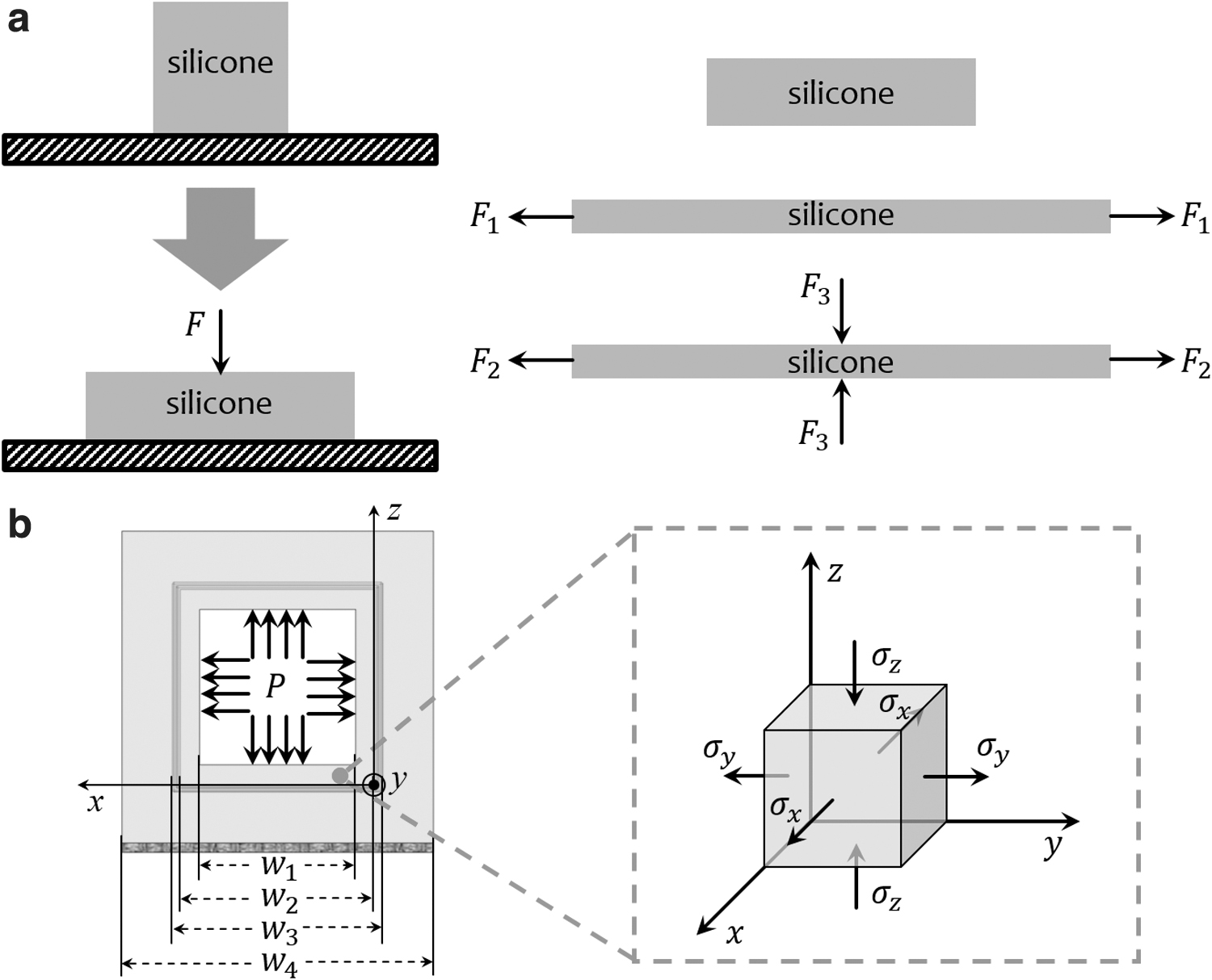
Illustration of compression effect.
To understand the compression effect, the stress analysis of the bladder material during actuation is conducted using the generalized Hooke's law. By looking at the infinitesimal cube chosen from the bottom bar of the bladder (Fig. 3b), we have the three following equations:
where ɛ, σ, E, and υ are strain, stress, general elastic modulus, and Poisson's Ratio (0.5) of the material, respectively; the subscripts x, y and z denote the three directions of the Cartesian coordinate system, respectively. In (8–10), the axial stress
By substituting Equation (11) for
Equation (12) means that, at the same strain, the axial stress
Modeling of SPA Bending in Free Space
With the material stress analyzed, the model of SPA bending in free space is given in this section. The bending model follows the typical steps as found in the study by Polygerinos et al., 1 which is to deduce the expression of the moment elements one by one. The moment components, which are either the function of input pressure or bending angle, are then added to the moment equilibrium. The equilibrium equation will then result in the relation between the bending angle and the input pressure by simple operation. Figure 4a gives the cross-sectional view of the SPA before and after actuation, which shows the relevant parameters, whereas Figure 4b gives the side view of the SPA bending segment after actuation, which indicates all the elements that generate the moments, such as the input pressure, stress of the SCL, stress of the silicones inside and outside the fiber wall, and the contractile force from the fiber wall. Please note that, during the modeling, we assume the profile stays square, although there will be slight bulging in the profiles. All the values of the known variables for bending and force modeling are given in Table 1.

Bending modeling diagram of the FR-SPA.
Values of the Known Variables for Bending and Force Modeling
Component moment
The moment of input pressure is the product of the input pressure, the channel cross-sectional area, and the moment arm, which is the half height of the SPA. Among them, the change in the air channel size during the bending process is fairly considerable, which, therefore, shall be taken into consideration. With the incompressibility of the silicone material, we can have the new channel width
where L is the length of the SPA bending segment.
After bending, the volume of the curved inner silicone structure is given as:
where
With the volume consistency, we have following calculations:
With the expression of
where we also use
During SPA bending, we assume that the SCL undergoes pure bending with the zero-stress line at the very bottom of the SCL. Then, we can have the expression of this moment
where
The moment of inner silicone stress takes the integration of the stress within the area in between the squares defined by
where
By substituting Equation (12) for
Here, we let
For the expression of
The expression of moment of outer silicone stress is obtained from a similar process compared with inner silicone, but with the original stress equation:
Here, we let
For the expression of
From the working principle of the PAM,48,49 we can see that, due to the pressure radially toward the fiber wall, the angled fiber applies force to the actuator in the axial direction. In the case of bending SPA, the fiber angle varies at different circumferential positions, therefore, for simplification, the fiber angle at the centerline position is chosen as the averaged fiber angle to calculate the force and moment generated by the fiber tension. Based on the force balancing model in the study of Carlo Ferraresi et al. 49 and the illustration in Figure 5a, we have the force balancing equation in the circumferential direction.
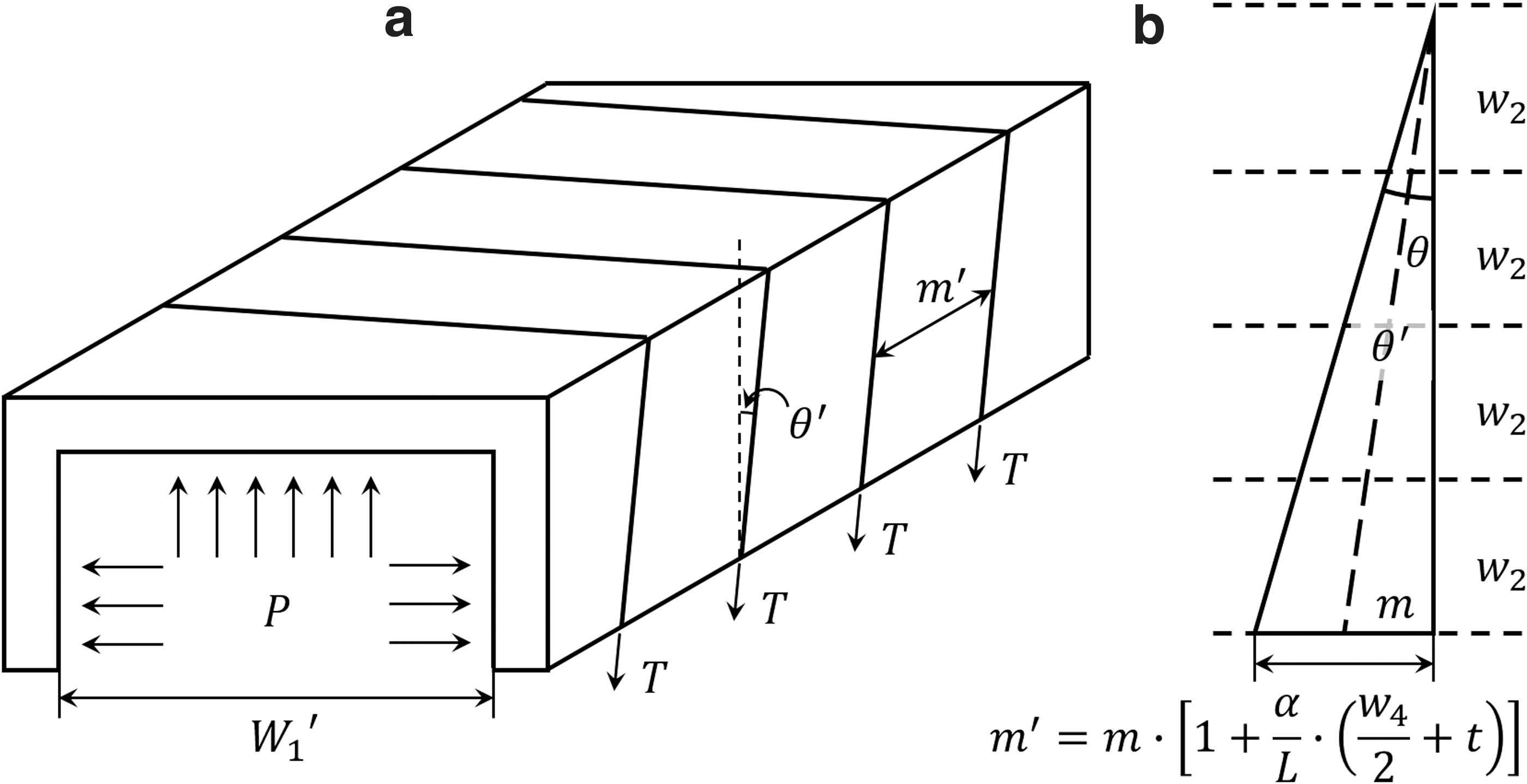
Fiber force analysis.
where
However, the force of fiber
Therefore, we need to obtain the expression of
Therefore,
Then, the moment of fiber
Here, we let
Here, we find that
Moment equilibrium
After having all the moment expressions, we then import them to the moment equilibrium shown below:
From the previous subsections, we know that
Modeling of SPA Block Force and Deflection upon Block Force
This section will elaborate how the FR-SPA deflection curve equation along with the block force model is obtained. According to the force measurement results in the study by Sun et al., 31 there was quite a large discrepancy between measurement and the model from the study of Polygerinos et al. 1 The discrepancy issue may lie with the fact that the deflection of the actuated SPA upon external loading is not considered. Figure 6a shows an actuated SPA (at 200 kPa) blocked by a load cell at the tip. It can be seen that the SPA segment near the fixation is in compression state with the neutral line curving rightward, and this compression will further increase the force output. Therefore, it is necessary to deduce the force model through establishing the deflection curve equation.

Force modeling diagram of the FR-SPA.
The overall process, similar to the bending modeling, is to deduce the moment components and then include them in the moment equilibrium. In the equilibrium equation, we will obtain the relation between force and curvature. The curvature is then substituted by the second-order derivative of the deflection from the approximate differential equation of the deflection curve of beams. Using simple integration and multiple boundary conditions, the solutions to the block force and the deflection can be derived.
There are some differences from the bending modeling, which are given below: (1) As mentioned in the Material Model section, the material model used in the force modeling is the linear model as it can easily combine the compressional and the tensile strain–stress relations of the material together. Therefore,
Component moments
During the external force application, the cross-sectional area of the inner chamber is changing along the length due to the changing curvature. However, since the strain along the SPA is rather small, the chamber size change is much smaller than the case of bending in free space. To simplify the model, we here temporarily assume that the SPA cross-sectional profile remains unchanged, which gives moment of P as follows:
Then
Please note that that change of chamber size will be considered at the end of the force modeling as the nonlinear factors.
The moment of stress in SCL is exactly the same as in the Component Moment section:
where
The moment of inner silicone stress is:
where
The moment of outer silicone stress is:
where
The moment of external force is given below:
where, as shown in Figure 6b, x is the distance from the proximal end to the point of calculation along the SPA length, therefore
Moment equilibrium
With all the moment components acquired, the moment equilibrium is given below:
where
As we know:
It is true that Equation (52) is mostly used in the cases of rigid beams with minor deflections; however, we still assume that Equation (52) is applicable to our SPA deflection as the SPA deformation is not that huge under the external force.
By substituting Equation (52) for
which is a typical second-order ODE, and its general solution is given below:
where
Since the proximal and the distal points are all locked in the y-direction by fixation part and load cell, respectively, we then have the first boundary conditions:
with which, we get
We then have
Furthermore, the SPA is fixed at the proximal end with zero body gradient at
from which, we can get
After substituting
Compared with the model from the study of Polygerinos et al.
1
:
With
Conclusively, this is a more sensible way to obtain the deflection curve equation and the block force model of the bending FR-SPA as both of them are co-related with each other. And, to the best of our knowledge, this is the first time that the block force model and the deflection curve equation of the FR-SPA are deduced this way.
Material and nonlinear factors
From the SPA force measurement, we observed that the force profiles are nonlinear and different for SPAs made of different materials; however, model Equation (62) yields the same linear profile regardless of the SPA materials, which, apparently, cannot speak for the results from the measurements. Therefore, as a quasi-iterative process, some material and nonlinear factors are added here to produce a new nonlinear block force model. There are two factors to be considered:
The change in the moment arm length
During the force application, the SPA curves with the pressure increase and the SPA tip moves upward along the load cell surface, which means that the distance from the fixation to SPA-load cell contact point, the moment arm length, is shortening. With the changing moment arm, the force will increase nonlinearly. Moreover, due to the different deformation rate upon pressure caused by the varied material stiffness, the force profiles of different materials can be differentiated.
To estimate the actual moment arm (AMA) length, a similarity assumption is used that the ratios of the neutral line length to the moment arm length in the calculation and the actual states are the same, as shown in Figure 7. The length of calculation moment arm (CMA) is

The material and nonlinear factors in the SPA force modeling.
where
Here is how
Then
Then
Therefore, the new force expression is
The change in the chamber cross-sectional area
As shown in Figure 6a, the deflection curve has a changing curvature, meaning that, at different points along the body, the material strain in the axial direction is not the same, which results in a changing inner chamber area. However, to simplify the calculation, we assume that due to the compression on the inner silicone wall by the inner compressed air, the inner silicone material is spread and thus form a uniform chamber size. This estimated chamber cross-sectional area is obtained based on the averaged strain of the SPA along its centerline at each pressure point. This averaged strain will then result in an averaged bending radian to calculate the new chamber width.
The averaged strain is obtained as follows: the second-order derivative of y is used to obtain the curvature function, which will then be used to obtain the strain function of the SPA centerline.
This strain function, via integration, will help to yield the total elongation of the SPA centerline during the force application. This centerline elongation divided by the length of the neutral line becomes the average strain
Then, we can get the averaged bending radian corresponding to
This method is like reforming the S-shaped central line and the neutral line into two uniform curvature arcs to form a radian
Then, the final force expression becomes:
In Equation (77), both
In the actual calculation, we will first form the force–pressure relation using Equation (62) and then obtain the deflection curve at each force point from Equation (62) using Equation (64). The deflection curve from Equation (64) will be used to calculate the
All the force- and deflection-related results from the models in this section are given in the Experimental Verification section to compare the experimental results.
Experimental Verification
This section presents the validation of the models from the previous two sections by comparing the model results with the experimental data. Specifically, this section includes the experimental methods and the verification of the SPA models for bending in free space, block force, and deflection curve upon block force.
Characterization method
The first experiment is the measurement of SPA bending in free space, which was conducted by fixing the SPAs on the fixation parts, as shown in Figure 8a. The SPAs were supplied with compressed air with pressure increasing at 2 kPa/s by a motorized pressure regulator (IR1020; SMC. Ltd). The experiment processes were recorded by a camera, which captured the SPA bending and the pressure display on the pressure sensor (ISE-30A; SMC. Ltd). The bending angles were measured from the videos using tracker software (https://physlets.org/tracker). All SPAs were actuated five times each, and only the last three tests were measured as the first two tests were only for material relaxation. This procedure was also applied to the force measurements.
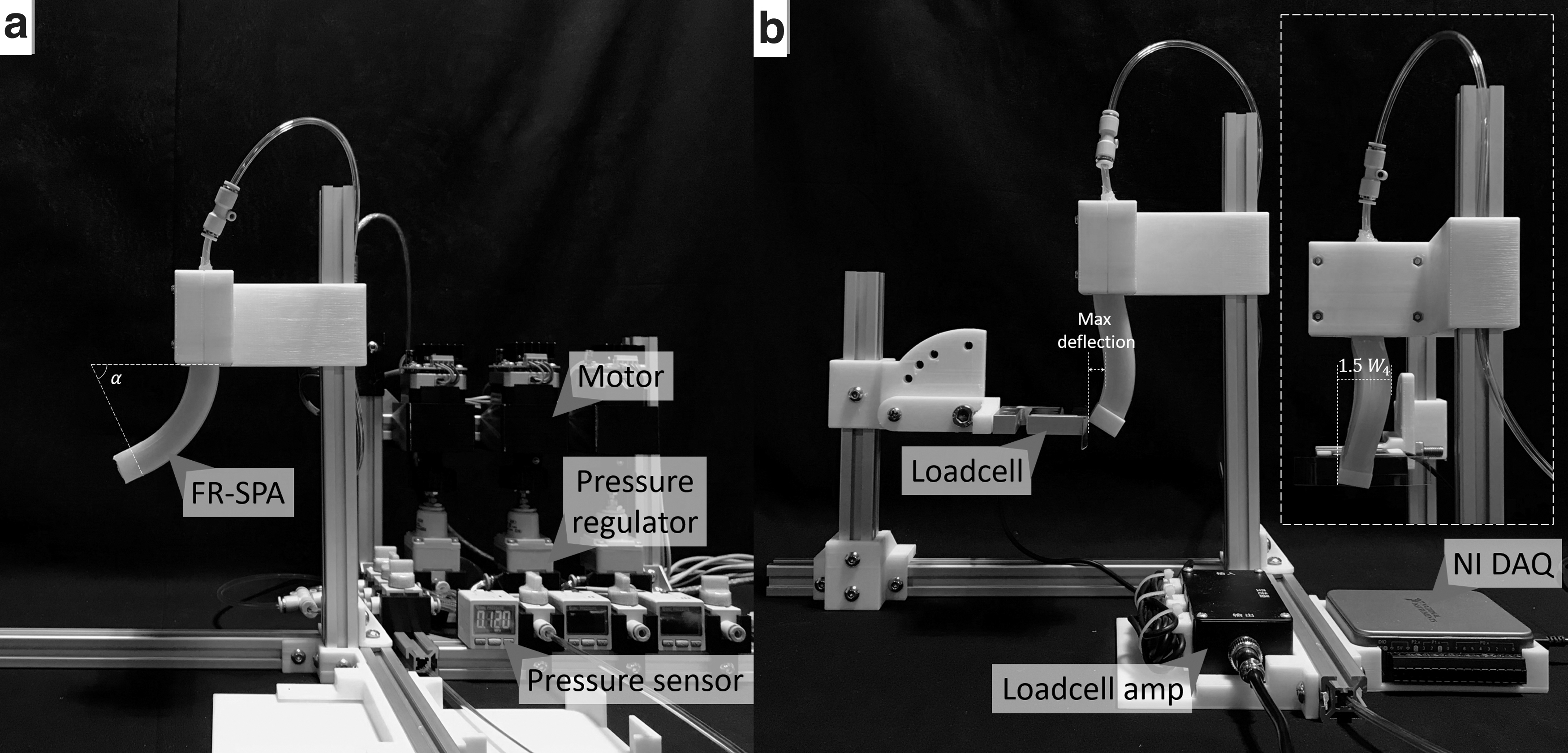
SPA characterization setups.
The force measurements proceeded similarly as the bending measurements, except that the SPA tip was blocked by a load cell (measuring range: 0–20 N), as shown in Figure 8b. To obtain the force output accurately, a 3D printed cube and a plastic strip were attached to the SPA tip and the surface of the load cell, respectively, to minimize the friction between the SPA tip and load cell. All force measurements were stopped after they buckled and the SPA tips slipped off the load cell surface. During the measurements, both the load cell and pressure sensor signals were captured by a DAQ (NI USB6003; National Instruments Ltd.) at 100 Hz sampling rate. The processes from the side views were also recorded for the measurement of the maximum deflections (Fig. 8b) along with the pressure increase using tracker. Besides, the buckling points of the SPAs were measured as an additional characteristic. According to the observations in the force measurements, the SPAs sometimes can stay at a largely twisted shape for quite a while before their tips slip off the load cell. Previously, the buckling point is defined as the moment when the SPA tip slips off the load cell,7,31 which may not be accurate because the largely twisted body is already the sign of buckling. Therefore, here, the buckling point is redefined as the moment when the lateral span of the SPA exceeds 1.5 times of its original width
Free-space bending model verification
Figure 9a gives all the averaged bending angle results of SPAs with different materials and cross-sectional profiles from the characterization, with the shaded area indicating the standard deviation (SD). All the experimental curves are accompanied by the model-predicted curves. As the most important feature, it is obvious that, for the same material, the two SPA cross-sectional profiles yield different bending angle curves. For example, EF30, DS10, and DS20 SPAs with 8-10-16 profile require around 55, 151, and 400 kPa, respectively, to reach 180°, whereas the SPAs with 8-14-16 profile only need about 40, 103, and 300 kPa, respectively, to reach the same amount of bending. Meanwhile, our model successfully differentiates the curves from the two profiles, whereas, according to the existing models, SPAs with the same inner and outer dimensions are supposed to have the same bending characteristics. By virtue of the stress analysis based on the generalized Hooke's law, we found out that the effect of the compression on the inner silicone wall will actually boost the bending, and the thicker the inner wall, the more boost the compression gives to bending. This feature was incorporated into the free space bending model and finally split the bending curves of the SPAs with the same inner and outer widths, but different inner wall thickness resulted from different fiber wall placements.

SPA bending, force, and deflection results from experiments and model.
Table 2 summarizes the discrepancies between the measured results and the model in the three performances, showing the averaged discrepancy (AD) and the maximum discrepancy (MD) at different series of pressures. Overall, the bending model gives fairly accurate bending predictions compared with the experimental measurements with AD range from 7.5° to 18°. More importantly, our model stands up well to the validation from the three silicone materials, while, in the previous works, their models were usually validated on one material.
Discrepancy of the Results Between Measurements and Model Predictions
Comparison points are the pressure points at which the bending, force, and deflection data are used to calculate discrepancies. The comparison points are selected to cover the full range of all the experimental tests.
AD is the average of all the absolute differences between the averaged experimental results and the model predictions at all comparison points for each test configuration. Particularly for the force results, the three SPA samples of each configuration buckled at different pressure; therefore, the measured force results are averaged until the smallest buckling pressure of the three samples. Due to force range difference, the discrepancy percentage compared with the averaged measured force at the last pressure points of their respective comparison ranges is also given beside the individual force numbers.
MD is the largest value among all the absolute differences between the experimental results and the model predictions at all comparison points for each test configuration.
AD, averaged discrepancy; MD, maximum discrepancy; SPA, soft pneumatic actuator.
One of the downsides of our model is that it cannot fully reproduce the nonlinearity of the measured curves, which caused some high MDs up to 30° according to Table 2. Our model does include some nonlinear factors such as the nonlinear material model and the changing chamber size, which outputs certain nonlinearity in the curves, specifically the increasing slopes in the beginning of the pressure rise. However, this nonlinearity only matches the initial half of the experimental curves, which also have clear increasing slopes. From the measured curves, especially the DS10 and DS20 curves, we can observe that the curves are like inclined S shapes with strong nonlinearity at the latter half of the curves featuring decreasing slopes. This S-shaped nonlinearity mostly resulted from the chamber bulging process, which is modeled in detail in the Supplementary Data with the illustrations of Supplementary Figures S1–S4 and the information in Supplementary Table S1. Particularly, Supplementary Figure S3d shows that all the profiles bulge with a decreasing slope along with the pressure rise. Therefore, at low pressure, the quickly increasing chamber size helps to increase the bending curve slopes, whereas at high pressures, the slowly changing chamber size is not able to support the increasing slope in the bending angle curve. In the meantime, the increasing material stiffness during the strain increase turns the direction of the bending curve into an S shape. However, despite the discrepancy in the nonlinearity, our model still gave a very decent prediction of the bending of the SPAs with different profiles and material stiffness at different pressures.
Block force model verification
Figure 9b gives all the force results from experimental measurements and different models. First, regarding the experimental results, which are the fourth measurements of the three samples in each SPA profile–material configuration, it is clear that different materials result in varied maximum force outputs with EF30, DS10, and DS20 SPAs reaching 2 to 3 N, 5 to 8 N, and 9 to 15 N ranges. Moreover, due to the SPA body curving and chamber deformation along the pressure increase, their force curves all have different extents of nonlinearity. These findings are commonly seen in the previous SPA studies.7,8,11,31,39 However, owning to the compression on the different inner silicone walls, all SPAs with 8-14-16 profiles are around 1.5 times larger than their corresponding SPAs with 8-10-16 profiles in terms of the force output, which is expected by our understanding of the mechanics within the SPAs.
From the model aspect, our linear model (all blue and red dashed lines) successfully distinguishes between the two SPA profiles. More importantly, our linear model gives much more precise force predictions compared with the model (purple dashed line) in the study by Polygerinos et al. 1 As a further step, our nonlinear model, based on our linear model, gets even closer to the measured data regarding the force magnitude and the nonlinearity. For the 8-10-16 profiles, the accuracy of the block force model is adequate for all three materials with ADs at around 3% and MDs <10% compared with the measured force at their respective last comparison pressure points. However, the nonlinearity of the experimental curves for the 8-14-16 profiles are more conspicuous, which raises the AD and MD up to around 8% and 24% compared with our model with the nonlinear factors. It is hard to give a full explanation for this deviation, but we believe that the chamber expansion from the profile budge is one of the reasons as our profile model in the Supplementary Data reveals that the 8-14-16 profiles has more bulge, and thus, more chamber size increases than the 8-10-16 profiles according to the estimated deformations of the inner chamber wall in Supplementary Figure S4. All in all, our models, deduced from the theory of elasticity, give fairly accurate force predictions, which can facilitate the control of the SPA forces.
The buckling characteristics for the SPAs under different configurations are given in averaged buckling pressures with lateral pressure span of two SDs to inform of the general buckling ranges (Fig. 9b). Clearly, they are also different depending on the profiles. Specifically, 8-10-16 profiles, buckling at around 88, 235, and 440 kPa for EF30, DS10, and DS20, respectively, are more resistant to buckling than the 8-14-16 profiles, which buckle at around 63, 174, and 350 kPa for EF30, DS10, and DS20, respectively, although they produce less forces. Moreover, the buckling ranges are not consistent for different SPA configurations. This is because buckling usually occurs upon random external disturbances when the internal force/stress antagonism of the SPA becomes unstable at high pressure. So far, buckling is still one of the key issues for SPAs and greatly impedes the SPA applications. Although there have been works on improving the SPA buckling resistance,7,50,51 the buckling theory of the SPAs has yet to be studied. With the deflection curve equation of the SPA during force application established in this article, the next goal is to build the model for the lateral buckling of the SPA using the similar procedure, which will tell the exact buckling points and the critical loads of the SPAs with specific designs.
Deflection curve verification
Besides the verifications of bending and force models, the deflection model of the FR-SPAs is also validated because this mode is also one of key contributions of this article. The actual validation focuses on comparing the maximum deflection and the deflection curve from the experiments and the equations at different pressure points.
Regarding the model predicted maximum deflection, the location for maximum deflection can be obtained when the first-order derivative of y is 0.
The results are:
Since there is no deflection at
Figure 9c gives all the averaged maximum deflections (solid lines) of the SPAs, with the shaded area indicating the SD. Again, different profiles output lines with varied slopes with 8-14-16 profiles yielding larger maximum deflections. Despite the different slopes, their maximum deflections before they buckle are within the same range (around 9–10 mm). Similar to what was observed in the bending and force verification, the nonlinearity of the curves gets stronger with materials of higher stiffness. For EF30, the experimental lines are almost straight (Fig. 9c.i), whereas the nonlinearity in DS20 curves become very obvious (Fig. 9c.iii). The dashed model lines, calculated from Equation (80), are fairly close to the experimental curves, and, most importantly, the model separates the curves from the two different SPA profiles. However, the mismatch between the model and experiment still exists, especially for DS20 case (Fig. 9c.iii). For the EF30 and DS10 SPAs, their measured values are always slightly smaller than the calculated data by differences ranging from 0.45 to 0.9 mm. For DS20, the discrepancies are small when P is smaller than around 160 kPa, beyond which, the measured values quickly exceed the model due to the nonlinearity with deflection MDs reaching up to around 2 mm at their last comparison points.
As a more visible verification, the deflection curves calculated from Equation (64) are aligned with the actual deflected SPAs at their respective high pressure points, which give more obvious deformation views, as shown in Figure 10. From the body deflections of EF30 (Fig. 10a, b) and DS10 (Fig. 10c, d), it can be seen that the modeled deflection curves fit very well with the SPA neutral lines from the fixation, and then, they start to part from each other slightly with the model curves bulging more than the actual SPA curves, which has been reflected by Figure 9c.i and c.ii. The reason for the extra bulge in the model is that the total effective SPA length for calculation is

Actual SPA body curves with modeled deflection curves at their respective high pressure points.
Conclusion and Future Work
In this article, we raised one important issue we observed in the FR-SPAs, which was also noticed and reported in the previous works of ours and others. The issue is that the SPAs would perform differently with varied silicone wall thickness within the fiber reinforcement. Our hypothesis is that the compression on the inner silicone wall by the inner compressed air has a strong impact on the mechanical properties of the SPAs. Guided by this hypothesis, we designed two cross-sectional profiles based on our previous SPA structure for validation. Before starting the modeling, we proposed our own material model and then conducted the stress analysis using the generalized Hooke's law to explain how the compression affects the stress of the SPA material in the axial direction. With the compression-induced new stress expression, we established the SPA models for bending in free space, block force, and deflection upon block force using the moment equilibrium method. Interestingly, our moment equilibrium in the force modeling resulted in the deflection curve equation, which, to the best of our knowledge, is the first obtained through a mechanics-based approach. Furthermore, by using the boundary conditions, we were able to obtain the new block force model, which was later incorporated with nonlinear factors to differentiate different materials. In the validation, our models produced fairly good predictions in bending, force, and deflection observed in the experimental results. Most importantly, all our models successfully exhibited the impact of the compression and differentiated the results from the two profile designs. We believe that the compression inside the SPAs should not be ignored as it affects the SPA behaviors substantially according to our results from the characterization. Therefore, the fiber wall placement should be listed as a new design variable for FR-SPAs, which can be critical for certain applications. For example, those self-contained soft robots for space or underwater applications might carry limited amount of actuation media. However, by designing SPAs with larger fiber walls and small channels, less actuation media will be needed for actuation, but the SPAs can still deliver decent performances. Furthermore, our models, although not generic, still have a wide utility scope. First, this model is applicable to SPAs with different elastic materials including a variety of natural or artificial elastomers and even hydrogel, as our material model can curve-fit these materials fairly easily and accurately. Second, any kind of SPA with radial reinforcement, including fiber, shell, and the like, can utilize this model as they all experience the compression effect during actuation, and the model can handle those SPAs with different cross-sectional profiles designs. Moreover, the block force with better accuracy, along with the deflection model, can serve as the new reference to estimate the block force and the deflection of the reinforced SPAs. This will be very significant, considering that block force is the mostly adopted evaluation of the strength of the SPAs and that most SPAs are actuated from a straight line. Last, with the compression effect, the fiber wall placement becomes a design parameter, and our model can be used to optimize this design parameter for the best SPA performance under the condition when very limited actuation media (compressed air and liquid) is available. All in all, by incorporating the compression effect, our model is one solid step closer to the truth of FR-SPAs, which provides new insights into the SPA mechanics. Moreover, with bending, force and deflection all modeled in one method with minimized computing intensity, this article can potentially serve as a comprehensive summary of the mechanics-based SPA modeling and facilitate the control of the different properties of the FR-SPAs in various applications.
In the future, we will continue our work in the SPA mechanics in different directions. First, the deflection theory, which is usually for solving the minor deflections of rigid beams, is applied upon the assumption that it is applicable to the SPA deflection upon the block force. However, a more generic deflection model that allows large deformation is desirable as it will help to solve the force and deflection problems under different loading configurations. The possible approach toward this goal is to study the elasticity theory of the curved beam and apply it to the FR-SPA cases. Second, we will also study the torsional deformation of the FR-SPAs based on the theory of lateral buckling of the curved beam, ultimately to establish the model for the SPA buckling and fully understand the SPA buckling mechanism, and find out their critical loads. Moreover, the nonlinearity in the measured results is conspicuous in different aspects of the SPA behaviors, but we neglected to include all the nonlinear factors in the models as it was not the purpose of this article and it would overcomplicate the modeling process. As part of our future research, we will incorporate more nonlinear factors into the current models, for example, the combination of the profile model into the moment equilibrium, to further improve our models.
Footnotes
Author Disclosure Statement
No competing financial interests exist.
Funding Information
This article was jointly supported by Sydney Institute for Robotics and Intelligent Systems and Australian Center for Field Robotics; the National Robotics Program (Singapore)—Robotics Enabling Technologies and Capabilities (R-397-000-332-305) directed by R.C.H.Y.; the National Natural Science Foundation of China under Grant 51905379, the Open Research Fund (2018IRS14) of Beijing Advanced Innovation Center for Intelligent Robots and Systems, and the Open Research Fund (MSV201916) of the State Key Laboratory of Mechanical System and Vibration awarded to P.Q.

Appendices
References
Supplementary Material
Please find the following supplemental material available below.
For Open Access articles published under a Creative Commons License, all supplemental material carries the same license as the article it is associated with.
For non-Open Access articles published, all supplemental material carries a non-exclusive license, and permission requests for re-use of supplemental material or any part of supplemental material shall be sent directly to the copyright owner as specified in the copyright notice associated with the article.
