
Abstract
In this study, we fabricated a nanofiber-based electrothermo-pneumatic soft actuator (ETPSA) using electrospinning technique. The actuator uses liquid–vapor phase transition. The ETPSA developed in the present study goes beyond the limitations of the existing pneumatic soft actuators. The present ETPSA has a built-in source of heat (Joule heating from an embedded metal wire) and allows the smooth anthropomorphic movement of the actuator and, in particular, eliminates the use of external pumping systems that are indispensable in the existing pneumatic soft actuators and robots. In addition, since the present ETPSA can be operated effectively even using a portable miniature battery, it holds great promise as an adaptable soft actuator for various robotic applications with high energy efficiency and programmable motions.
Introduction
Over the past 60
In contrast, living creatures have been effectively adapting to diverse natural environments, particularly based on their physical flexibility that originates from the softness of their bodies and structures. 7 For example, an octopus can easily modify its body shape according to a complex topography using contractions and relaxations. In this context, numerous studies intended development of performance-improved soft robotics and focused on the use of soft materials mimicking the remarkable adaptability of living creatures. 8 Accordingly, novel soft robots developed have hitherto demonstrated high economic feasibility and safety along with attractive features (e.g., light weight, ease of fabrication and customization, and feasibility of usage in various environments).4,9–12
To develop novel soft and high performance robotics, various soft materials such as responsive polymers,13,14 hydrogels,15,16 ion exchange materials, 17 elastomers,18–21 and electroactive polymers22,23 have been actively used so far. Accordingly, soft robotic actuators built of these materials could operate adopting an electromechanical mechanism based on pressurized fluids, compressed air, electric and magnetic forces, and thermal sources. Among them, the most common approach for operating an actuator is the use of an external compressor that supplies air at high pressure into the body of the soft actuator to pneumatically induce its bending. 24 However, in practice, the use of an external compressor and associated mechanical components limit miniaturization of such soft actuators for broadening their potential applications because the system is bulky and heavy. 25 Accordingly, the aforementioned approaches have the disadvantage of low portability. Moreover, they require high energy and specific external conditions to be operational.13,14,18,26
In contrast, soft robots that operated using chemical materials were also explored.27,28 However, they were inappropriate to operate pneumatic robots that required high pressure. 29
Novel soft actuators driven by liquid–vapor phase transition have been recently developed and introduced to overcome these issues. The working mechanism of these soft actuators is based on their volume expansion driven by thermal energy.
So far, various studies have been conducted to induce the expansion of the working fluid inside such soft actuators. For example, An et al., 5 in a recent study of these thermo-pneumatic soft actuators, used an external heat source to supply thermal energy into the actuators, which contained a volatile liquid inside their soft bodies. 6 Boyvat et al. used magnetic field to remotely heat the soft actuator. 30 Similarly, Han et al. used remote heat stimulation using an infrared (IR) laser to heat and expand the working fluid inside the soft actuator. 11 These are thermally-driven actuators, unsubstantiating the use of air compressors, which are heavy and bulky.
Even though these studies have introduced novel and unique techniques for thermo-pneumatic soft actuators demonstrating remarkable performance, these actuators required significant energy supply from external sources, which is rather inconvenient. It would be better to have a heat source internally within the system so that soft actuators are mobilized by its operation alone without changing the external environment, which is difficult to control. In addition, most of the fabrication methods reported in these studies were complex and cost ineffective.
To circumvent all of these aforementioned issues, in this study, an electrothermo-pneumatic soft actuator (ETPSA) is developed, which removes the necessity in controlling the external environment and the use of bulky air compressors. The heater is installed internally within the system, and the liquid–vapor phase transition is achieved by heating without the use of any air compressor. First, the fluid was stored using a porous nanofiber (NF) mat, and the highly porous NF mat allowed the inside liquid to be well distributed in the entire inner space of ETPSA during expansion and contraction by heating and cooling, respectively. In this study, the volumetric expansion of the actuator is driven using Joule heating of metal wire embedded in its body.
In addition, because the energy required for triggering actuation of the device is circumscribed within the device only, the operation energy cost would be significantly less than the actuation system requiring the external heating. Therefore, the proposed soft actuators herein and their fabrication techniques are economically viable compared to other actuators. In addition, the current system does not require multiple external devices for operation, is easy to fabricate, and is portable and adaptable.
Experimental
Materials
Polyacrylonitrile (PAN, Mw = 150 kDa; Sigma-Aldrich, USA) and N,N-dimethylformamide (DMF, 99.8%; Sigma-Aldrich) were used for fabricating electrospun PAN NF mats. The engineering fluid, Novec 7000 (Sigma-Aldrich), was used as the working fluid of the ETPSA developed in the present study (cf. Electrothermo-Pneumatic Soft Actuator section). A 300 μm thick paper towel (Yuhan-kimberly, Republic of Korea), which was used for blocking and forming the passive layers of the actuators was sourced locally. The resin and cure liquids, Ecoflex 00-30 and Ecoflex 00-35 (Smooth-On, USA), were used for shaping the body frame of the actuators.
A house-made aluminum mold with an inner volume of 12 cm × 3 cm × 1 cm was used for shaping the body of the soft actuators during their production. A heating wire (SILVER No.4, Silver KOHKI, Japan), composed of chromium (20 wt. %), aluminum (3 wt. %), and iron (77 wt. %), was prepared and installed inside the actuators to heat the working fluid.
Electrospinning
PAN was dissolved in DMF at the concentration 8 wt. % and magnetically stirred to form a homogenous PAN solution. The 8 wt. % PAN solution was then electrospun onto a rotating drum of radius and width of 20.5 and 30 cm, respectively. The drum was rotating at 200 rpm. A potential difference of 8 kV was applied between the drum collector and the 18G needle (Nordson EFD, USA) issuing polymer solution.
A DC (direct current) voltage supply (Glassman High Voltage, USA) was used for charging and electrospinning the PAN solution, which was supplied at the fixed flow rate of 800 μL/h using a syringe pump (Legato 100; KD Scientific Inc., USA). The distance between the drum collector and the needle exit was 15 cm. The total time of electrospinning was 91 h, which allowed fabrication of a large-area thick NF mat with the width, length, and thickness of 40 cm, 90 cm, and 180 μm, respectively.
Characterization
The surface morphology of the electrospun PAN NF mats was studied using a field-emission scanning electron microscope (FE-SEM/EDX, Quanta 250 FEG, FEI). The average diameter of the PAN NFs and the radii of curvature of the actuators were analyzed using the I′Measure3 software (IngPlus, Republic of Korea). A digital force gauge (FG-6020SD; Lutron Electronic, Taiwan) was used to measure the pulling forces obtained by the actuators. A voltage supply (SPS-1820; GW INSTEK, Republic of Korea) connected to the heating wire heated it by manipulating the applied voltage and current. The photographs in this study were obtained using a digital camera (EOS600D; Canon, Japan). A thermogravimetric analyzer (Q500; TA Instruments, USA) was used to explore thermal stability of the Ecoflex.
Results and Discussion
Electrothermo-pneumatic soft actuator
The ETPSA developed in the present study consisted of six layers, as illustrated in Figure 1a: (1) the first Ecoflex layer, (2) PAN NF layer, (3) the first passive layer, (4) the heating wire layer, (5) the second Ecoflex layer, and (6) the second passive layer. The actuator was fabricated by stacking each layer consecutively in a house-made aluminum mold (cf. Materials section).

Before the fabrication of the ETPSA, a large-area thick electrospun PAN NF mat was prepared using an electrospinning setup equipped with a drum collector (Fig. 1b; cf. Electrospinning section). The fabrication method of the PAN NF mat is similar here to that reported earlier by the present group for thermo-pneumatic soft actuators.5,6 The large-area PAN NF mat produced was cut into small rectangles of sizes of 2 cm × 6 cm (Fig. 1c), which were used for the PAN NF layer of the ETPSA (cf. Fig. 1a). Details of the fabrication steps of the ETPSA are described in Supplementary Data; see Supplementary Fig. S1. In contrast, it should be emphasized that the highly porous PAN NF mat was used to imbibe the working fluid within the body of the ETPSA (cf. Materials section). The average diameter of the PAN NFs was 620.60 ± 137.09 nm (Fig. 1d).
Figure 1e describes the ETPSA at the initial state (corresponding to the cooling state of the wire embedded in the ETPSA), whereas Figure 1f shows the ETPSA at the heating state of the wire. As shown in Figures 1e and f, the ETPSA could be operated by either cooling or heating the wire, which was possible because the external electric circuit was connected to the wire inside the ETPSA (Fig. 1g). When the external circuit is open, the ETPSA does not operate because no Joule heat is generated. When the circuit is closed and a voltage is applied, volatile Novec 7000 is heated using Joule heating, resulting in the asymmetric bending motion of the ETPSA.
Thus, the high thermal energy generated by the wire inside the ETPSA leads to the liquid–vapor phase transition of the volatile working fluid, resulting in a significant volume expansion of internal space of the ETPSA (Fig. 1g). In particular, it should be emphasized that the asymmetric unidirectional expansion, which occurs owing to the presence of the passive layer (cf. Fig. 1a), facilitates the unidirectional bending motion of the ETPSA (Fig. 1e, f). In other words, the internal structure of the ETPSA, rendered mechanically asymmetric by the presence of the passive layer, allows the anisotropic expansion of the ETPSA (otherwise, the ETPSA would evenly expand in all directions5,6).
This unidirectional bending motion of the ETPSA is one of the key features beneficial for its use in the field of soft robotics. Note that the heating wire inside the ETPSA, which was very thin and light with a diameter of 0.2 mm and weight of 0.23 g/m, was also bendable, which allowed the ETPSA to be bent smoothly during its operation. In addition, the wire has a high resistance of 39.15 Ω/m and can generate temperatures up to 1100°C.
The operational stability of the ETPSA, without any thermal degradation within the operating temperature range, was explored by measuring the weight change of the Ecoflex from room temperature to 200°C (Fig. 1h). We note that the temperature of 200°C is attainable when the voltages between 6V and 8V are applied to the wire inside the actuator (cf. Fig. 2a). As the temperature increases with a ramp rate of 10°C/min, the corresponding weight of the Ecoflex decreases slightly (by only 3% at 200°C), as shown in Figure 1h. This was attributed to the sublimation of the volatile substances in the Ecoflex 00-30.31,32 The result indicates that the soft body of the ETPSA is insignificantly degraded during the operation of the ETPSA, even at 200°C.

Heating performance of the wire inside the ETPSA
Figure 2a shows the change in the temperature of the metal wire inside the ETPSA as a function of the applied voltage. Note that these heating tests were conducted outside the ETPSA, using a wire which was as long as the one inside the ETPSA (14 cm). The voltage applied to the wire was increased in steps of 2V from 2V to 10V, and each step was maintained for 200 s. In the typical range of voltages from 0V to 10V produced by commercial batteries, the wire is capable of increasing temperature up to 347.3°C (Fig. 2a), which is high enough to heat the entire soft actuator and the fluid in contact with the actuator up to the fluid's boiling point. In Figure 2a, the heat removal to the surround air from the heating wire could be neglected because air is a practically perfect thermal insulator. However, it should be emphasized that the actual temperature of the heating wire inside the ETPSA would be slightly lower compared with the heating wire observed in Figure 2a because it was surrounded by coolant and soft body that can transfer heat. Thus, the internal temperature of the ETPSA can be in the operational range and adjusted even using commercially available batteries, which is expected to accelerate the practical use of the ETPSA in the near future.
Figure 2b shows the average values and the corresponding standard deviations of the wire temperature as the applied voltage is increased. As the applied voltage increased in steps of 2V from 0V to 10V, the corresponding temperature increased to 50°C, 90°C, 160°C, 240°C, and 330°C, respectively. The standard deviations of the temperature in Figure 2b tended to increase as the applied voltage increased. This was attributed to the fact that the wire generated heat upon the voltage application and also acted as a constant voltage anemometer. In general, even for a fixed applied voltage, the heating wire can react very sensitively to the surrounding environment according to King's law
33
:
where Pw is the power dissipated by the heating wire, Rw is the resistance of the heating wire, and Ra is the resistance of the fully cooled wire, whose temperature is the same as the ambient temperature. The constants A and B are associated with the wire properties, and the function f(U) = U n, where U is the air velocity perpendicularly to wire, with n being an experimentally determined coefficient (which is generally n ≈ 0.5). In other words, Rw, which is associated with the wire temperature, correlates with Pw, the ambient temperature (via Ra), and the air normal velocity magnitude (U), which might be either zero or positive.
Although the experimental conditions were under tight control, some experimental parameters associated with Eq. (1) could not be controlled fully. For example, while Pw could be controlled by fixing the voltage applied to the wire, the ambient temperature and velocity of the surrounding air could not be completely controlled in the present case, which caused fluctuations in the wire temperature (corresponding to variations in Rw), as illustrated in Figure 2b and d. However, this effect was insignificant, and the wire temperature fluctuations lay within 10% (Fig. 2). This did not affect the performance of the ETPSA significantly.
Figure 2c depicts the change in the heating wire electrical resistance as a function of the applied electric power. In this study, the applied electric power P was calculated using Ohm's law as P = V
2
R−1 [W]. The resistance increased from 4.7 to 5.7 Ω as P increased, because the resistance of metals varies with temperature as follows
34
:
In this study, R and R0 are the resistances at temperature T and the reference temperature Tref (which is generally 20°C), respectively. The coefficients a1, a2, …, an are the temperature coefficients of the resistance of electrically conductive materials. As P is increased, the corresponding wire temperature increases linearly from 26.1 to 331.5°C (Fig. 2c), while the corresponding value of the first derivative of the temperature by power gradually decreased to ∼12°C/W. In other words, as the power applied to the actuator increased gradually, the corresponding resistance of wire also increased and became almost constant above P = 12 W, as indicated in Figure 2c. Accordingly, a relatively slow temperature increase with power was observed.
Figure 2d shows the wire temperature when a constant voltage of 5V was applied for 5400 s. The temperature increased rapidly to 112°C at the beginning and then plateaued at ∼108°C for 5387 s. As the applied voltage was cut off, the temperature decreased almost instantly.
Because the wire inside the ETPSA undergoes considerable bending as the ETPSA is bent unidirectionally due to buckling in presence of the passive layer, a stable heating performance of the metal wire during bending is important for the ETPSA performance. In Figure 2e, the variation in the electrical resistance of the wire was measured as its curvature increased. The resistance increased from 0.45 to 0.71 Ω/cm as the curvature increased from 0 to 1000 m−1, while it began to decrease to 0.46 Ω/cm as the curvature increased from 1000 to 1542 m−1. The initial increase in the resistance was associated with elongation of the wire. 35
As bending progressed, the radius of curvature decreased and the neutral axis, which is a theoretical axis lying at the center of the wire, shifted toward the inside surface of the bend. The area between the neutral axis and the inside surface is subjected to compressive force, and on the contrary, the area between the neutral axis and the outside surface is subjected to elongation force. As the neutral axis shifts toward the inside surface of the bend, the tensile force acts on the wire and thus, the wire is generally thinned at the bend. When a certain part of wire is elongated, the length increasing and the cross-sectional area decreasing, the resistance of the wire increases. In contrast, the reduction in the resistance regardless of a still increasing curvature in the 1000–1542 m−1 range was related to the fact that the neutral axis shifts outward in the bend in case of the excessive bending. This causes an increase in the cross-sectional area, thereby decreasing the resistance of the wire.
Figure 2f shows the change in the wire resistance during the cycling test with the fixed bending curvature of 1542 m−1. Note that 1200 bending cycles were conducted in total, and the resistance was measured after every 100 cycles. The wire resistance remained almost constant for the 1200 cycles, demonstrating stability in the performance of the ETPSA even after a thousand bending cycles.
Bending performance of the ETPSA
Figure 3 illustrates the performance of the ETPSA. The performance was explored in terms of five parameters as follows: (1) bending speed (cf. the change in curvature vs. time), (2) stability during repeated bending, (3) durability under long-time bending, (4) output force, and (5) input energy for bending. To calculate the bending speed and stability during bending, changes in curvature as a function of time and bending cycle were examined. Similarly, for exploring the durability under long-time bending, the change in curvature for long-time operation was observed. The output force from the ETPSA was measured using a force gauge. The change in curvature with respect to the input energy was obtained from the results for the bending speed.

Bending performance of the ETPSA
Figure 3a shows the changes in the curvature of the ETPSA as a function of the applied voltage (cf. Supplementary Movie S1). The volume inside the ETPSA increased asymmetrically, leading to bending (essentially, buckling, in the rigorous theory of elasticity sense) over time. The curvature was found to increase as the applied voltage increased in all cases. As shown in Figure 2a, the voltages of 4V, 6V, and 8V gradually raise the temperature inside the ETPSA. The corresponding temperature range of the heating wire was ∼80–250°C, which is significantly higher than the boiling point of the working fluid (i.e., 34°C for Novec 7000). However, the required amount of power is very small (<15W) because the required electrical current remained <1.5A (Fig. 2c). The curvature of the ETPSA was 30.41 m−1 for 180 s at 4V, while its values at 6V and 8V were 54.22 m−1 for 131.82 s and 51.08 m−1 for 70 s, respectively. In other words, the rates of the curvature variation at 4V, 6V, and 8V were 0.17, 0.41, and 0.73 m−1/s, respectively. Note that the maximum curvature at 8V was lower than that at 6V because of the degradation of the soft body (i.e., Ecoflex) after 70 s. Note that, according to the technical note of Ecoflex given by the manufacturer, 36 the allowable temperature of Ecoflex is under 232°C. Thus, Ecoflex can be degraded at the applied voltage of 8V, because the temperature of the heating wire reached to 240°C at this voltage (Fig. 2b). Accordingly, the applied voltage of 8V was unsuitable for the operation of the ETPSA in the present study.
Figure 3b describes the rate of change of the curvature over 30 cycles. It should be noted that Ecoflex is a porous elastomer, and thus, perfect sealing of the fluid within cannot be achieved; leak is unavoidable during multiple operations. Overall, ∼5–10% of the initial amount of fluid is lost after five to six expansion/contraction cycles. Thus, ∼5–10% of the working fluid (i.e., Novec 7000) in the ETPSA was resupplied at every five cycles. In Figure 3b, no degradation in the bending performance was observed during 30 cycles, which confirmed the sustainability of the ETPSA. Figure 3c shows the time period over which the high curvature of the ETPSA can be maintained at the fixed applied voltage of 6V. The reasonable curvature change of 64.19% observed even after the long-term operation of 670 min demonstrated the high durability of the ETPSA.
In addition to bending, the pushing force generated during ETPSA bending was also studied, and the corresponding results are presented in Figure 3d. When the applied voltage was increased, the corresponding pushing force associated with ETPSA bending increased. Interestingly, in the graph for the pushing force versus time (Fig. 3d) a plateau at ∼40 s (0.04–0.06 N) appeared in both the 4V and 6V cases.
This can probably be attributed to the effect of the boiling mechanism. When heat is supplied from the heating wire, the surface of the heating wire begins to generate microbubbles associated with nucleate boiling, thereby increasing the vapor pressure inside the ETPSA. The vapor pressure at this process is linked with an initial increase in the pushing force as revealed in Figure 3d. As the heating temperature increases, the surface of the heating wire sustains transition boiling, in which most of the energy supplied from the heating wire is spent for the phase transition of liquid into vapor. In this process, the volume of the ETPSA increases, while the internal vapor pressure remains constant, determining a constant value of the pushing force, as in the plateau in Figure 3d. As the further heating proceeds, film boiling occurs at the surface of the heating wire, accelerating the vapor expansion inside the ETPSA, which increases the pushing force beyond the plateau.
The ETPSA exhibited a pushing force of 0.08 N for 120 s when the applied voltage was 4V. It yielded a higher force of 0.26 N for 120 s when 6V was applied. The force generated when 6V was applied was 3.2 times higher than the force generated at 4V. This was attributed to the higher vapor pressure of Novec 7000 inside the ETPSA driven by the higher temperature compared to the 4V case. 37 Note that the pushing force of 0.26 N led to a pressure of 3.31 kPa, based on the diameter of the rod connected to the force gauge (1 cm). That is, within the voltage range that did not damage the Ecoflex (≤6V; cf. Fig. 3a), the on-demand control of the ETPSA (i.e., the final value of curvature, the rate of curvature change, and the pushing force) is feasible by varying the applied voltage.
Furthermore, the input energy Einput can be calculated using Ohm's law as Einput = V I Δt. Figure 3e shows the curvature of the ETPSA as the input energy was varied. The increase in the curvature of the ETPSA appears to be proportional to the increase in the input energy. The slopes corresponding to the applied voltages of 4V, 6V, and 9V were 0.070, 0.056, and 0.076 m−1/J, respectively, and the average value for these three cases was 0.068 ± 0.0082 m−1/J.
This linear dependence of curvature on the input energy also confirmed the effective conversion of the applied energy into the kinetic energy associated with bending motion of the soft actuators. In contrast, there were slight differences at the beginning of bending between the different cases, which were attributed to slight differences in fabrication of the actuators (i.e., the amount of working fluid injected inside the actuator, the overall structural difference between different actuators, temperature variation in the surrounding air, and so on).
The other soft actuators required additional devices or systems for operation, including an external near-IR light, 11 external temperature regulator,38,39 pressure control valve, 40 external pressure source, 41 external pressure regulator, 42 external oven, 6 solar simulator, 43 or high voltage supply, 44 as described in Figure 3f and Table 1. In comparison, ETPSA developed in the present study can operate effectively with a simple embedded metal heating wire powered by a small commercial battery. This makes the present ETPSA production and operation cost-effective (cf. Supplementary Movie S3).
Comparison of the Performance of Soft Actuators Reported So Far
3D, three-dimensional; IR, infrared.
Potential applications of the ETPSA are shown in Figure 4. In the first case, a human hand was mimicked using five ETPSAs (Fig. 4a; Supplementary Movie S2), with each module (ETPSA) connected to a light and easily replaceable commercial 9V battery (6LR61; ASUNGHMP, Republic of Korea).
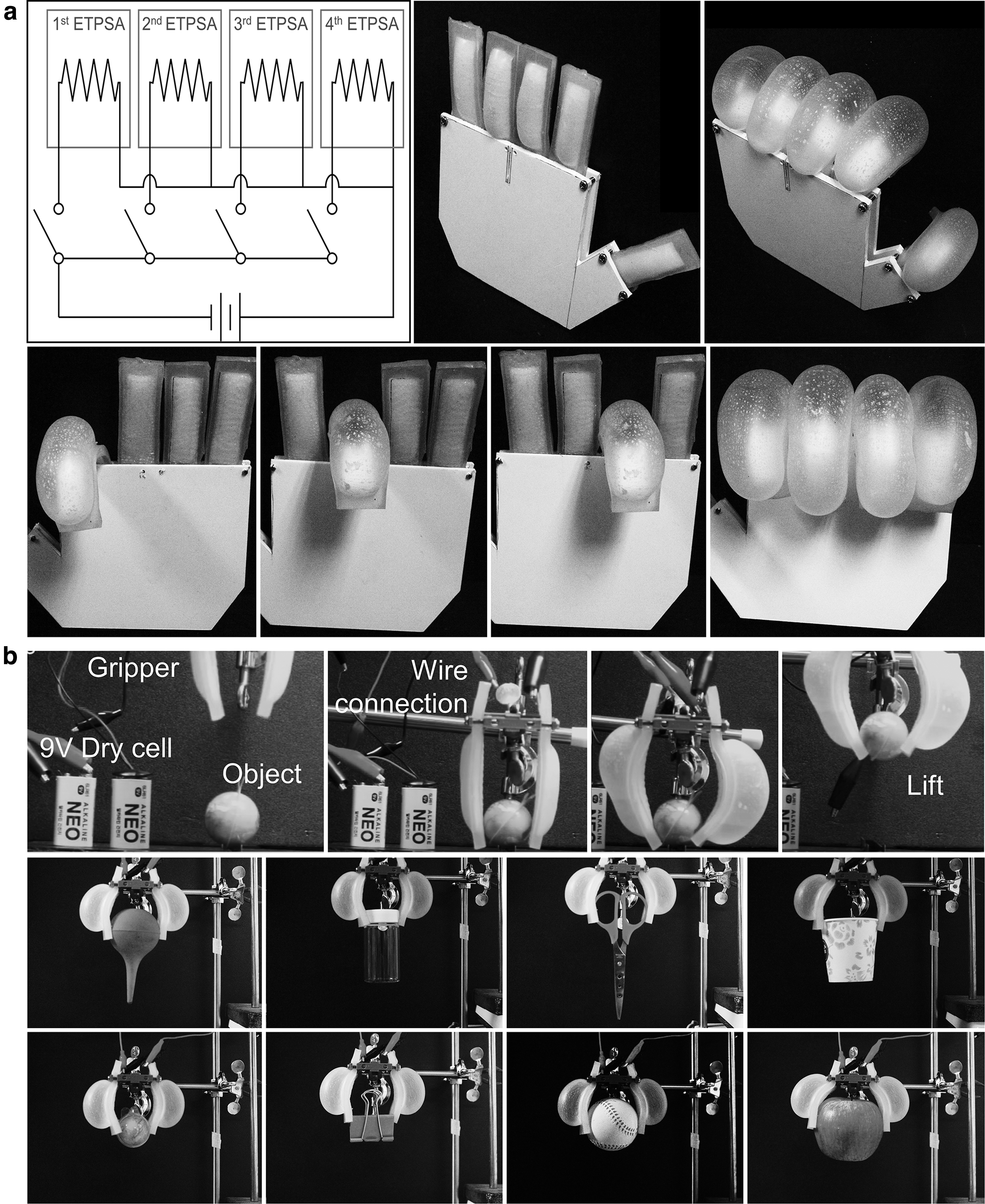
Operation as
In the second case, a gripper with two ETPSAs and a three-dimensional printed base was prepared as shown in Figure 4b. The gripper, which used a single 9V commercial battery, was able to smoothly pick an object up (Supplementary Movie S3). In addition, this gripper could also lift various objects of different shapes and weights from 3 to 150 g. In contrast to the other pneumatic soft actuators reported earlier, in which a complex pressure supply tube, high power electrical wires, or external energy sources were necessary for operation (Fig. 3f; Table 1), the ETPSA demonstrated in the present study required only a small, low capacity battery (e.g., commercial 9V batteries).
Conclusion
A programmable and portable cost-effective ETPSA was developed based on a facile and scalable electrospinning method. The ETPSA was thermally responsive and used an embedded metal wire for Joule heating. The use of the light and flexible soft metal wire and the volatile working fluid with a low boiling point enabled the effective operation of the ETPSA, even at low applied voltages. In fact, commercial 9V batteries were sufficient to fully operate the ETPSA in an artificial hand or a gripper without using additional energy sources and devices.
A single battery can be used for all fingers, if they move one after another, or a battery per finger, if simultaneous movements are required. The ETPSA proposed in this study was able to achieve a reasonable bending speed of 0.73 m−1/s during multiple cycles (30 cycles). In addition, the ETPSA could operate even for 670 min without significant degradation in bending performance. It was also possible to smoothly pick up various objects benefiting from the operating (or pushing) force of 0.26 N.
Footnotes
Author Disclosure Statement
No competing financial interests exist.
Funding Information
This work was supported by the National Research Foundation of Korea (NRF) grant funded by the Korea government NRF-2020R1A5A1018153, NRF-2021R1A2C2010530, 2020K1A3A1A74114847, and NRF-2016M1A2A2936760. The authors acknowledge King Saud University, Riyadh, Saudi Arabia, for funding this work through Researchers Supporting Project number (RSP-2021/30).
References
Supplementary Material
Please find the following supplemental material available below.
For Open Access articles published under a Creative Commons License, all supplemental material carries the same license as the article it is associated with.
For non-Open Access articles published, all supplemental material carries a non-exclusive license, and permission requests for re-use of supplemental material or any part of supplemental material shall be sent directly to the copyright owner as specified in the copyright notice associated with the article.