




Abstract
Elastic pneumatic actuators are fueling new devices and applications in soft robotics. Actuator miniaturization is critical to enable soft microsystems for applications in microfluidics and micromanipulation. This work proposes a fabrication technique to make out-of-plane bending microactuators entirely by soft lithography. The only bonding step required is to seal the embedded fluidic channels, assuring the structural integrity of the microactuators. The process consists of fabricating two SU8 mold halves using different lithographic layers. Polydimethilsiloxane is poured on the bottom mold, which is subsequently aligned and assembled with the top mold. The process allows for out-of-plane actuators with a diameter of 300 μm and for fabricating arrays of up to 36 actuators that are row addressable. These active micropillars have an aspect ratio of 1:1.5 and, when pressurized at 1 bar, show a bending angle of ∼30°.
Introduction
Flexible actuators are a key technology for the development of new microscale systems that mimic active biological tissues. In addition, soft actuators have the advantage that they typically do not have joints and therefore they do not suffer from friction and phenomena such as stick-slip. 1 As a result, they are attractive for bio-micro electromechanical systems, minimally invasive surgery, microfluidics, and microrobotics. 2 In this work we seek to develop arrays of soft flexible microactuators. More specifically, we are studying flexible active micropillar arrays, which may be adopted in the future as micromixing and micropumping devices 3 by mimicking biological cilia.4–9
To date, most artificial cilia consist of micropillars that are made out of a composite material consisting of an elastomeric matrix with magnetic micro or nanoparticles as a filler for actuation using a magnetic field.10–14 While impressive, a limitation in these flexible magnetic actuators is that they are controlled by an external magnetic field, which limits the local control of the cilia motion. The latter is important to achieve symmetry breaking in the motion of the cilia, which is crucial to create propulsion in low Reynolds number regimes.
Recently, our research group has shown that these issues can be alleviated by changing actuation principles and using out-of-plane soft inflatable bending actuators.15,16 Inflatable soft actuators rely on a pressurized fluid (typically air) to inflate an elastic structure and hence generate motion. These soft pneumatic actuators can be designed to generate different types of deformation such as extension, contraction, bending, and twisting. 17 The bending motion of these actuators is created by pressurizing a cavity that is placed eccentrically with respect to the longitudinal axis, resulting in a bending motion toward the stiffest part of the cross section.
Initially, small-scale pneumatic bending actuators were fabricated by bonding two polydimethilsiloxane (PDMS) sheets processed using soft-lithography two-dimensional (2D) micromolding. 18 However, this design can suffer from delamination issues between the bonded layers, as well as a large dimensional variability due to manual cutting steps that are required.
An alternative approach for fabricating these devices is using a three-dimensional (3D) mold that alleviates the need for bonding different layers and for manually cutting.19–21 However, the fabrication of the 3D molds using classic manufacturing processes (micromilling and microdrilling) results in actuators that can have outer diameters down to 1 mm and is a limit to further downscaling. Moreover, this production process makes it difficult to fabricate actuators in large arrays, due to the manual assembly of the molds. To avoid these assembly challenges in small-scale inflatable actuators, a laser cutting process has been proposed using sheets of thermoplastic polyurethane, 22 as well as a process using a combination of lithography and dry etching of PDMS. 23 These techniques allow for a rapid manufacturing of small actuators but cannot be used for direct fabrication of 3D out of plane actuators.
This work explores a new approach for fabricating 3D small-scale soft actuators with all dimensions in the sub-millimeter range using lithographically fabricated micromolds. This enables to further decrease the actuator dimensions and to address the challenges in fabricating actuator arrays using the processes described above. Compared to similar molding processes described previously, the lithographic micromolding process developed in this work allows reducing the diameter of these actuators by more than threefold, and arrays of 36 actuators are fabricated in one step, which is an important improvement over current piece-wise fabrication methods.
Materials and Methods
Mold design
The lithographically developed molds in this work consist of two parts (top and bottom mold) as depicted in Figure 1. The bottom mold consists of a multiple-layered SU8 structure on a Si wafer. The top part is a free standing SU8 structure consisting of a single layer.
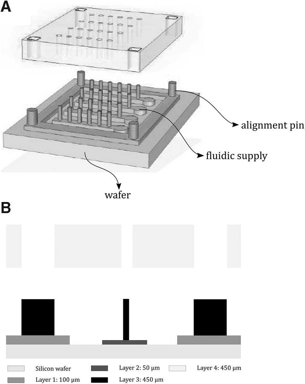
The bottom mold consists of three lithographical layers, all with a different height (Fig. 1) thus requiring the design of three photomasks. The first layer forms the rectangular outside walls of the mold that are 100 μm thick. The thickness of the walls defines the vertical position of the top mold and therefore the thickness of the base of the microactuators. The second layer is 50 μm thick, shown in yellow in Figure 1, and defines the fluidic channels that connect the microactuators' internal voids to the pressure supply. The connection with external tubing is made by punching a hole in a circular feature (2 mm in diameter) with a biopsy punch and inserting a tube. The last layer of the bottom mold defines the 450 μm long pillars corresponding to the inner cavity of the actuator that are placed on top of the fluidic channels. The radius of the pillars (r) is 90 μm. Moreover, this third layer defines the alignment pins located at the four corners of the outside wall. Those alignment pins are 400 μm in length and 500 μm in diameter, and their function is to align both halves of the mold.
The top mold is a rectangular SU8 plate that is 450 μm thick, which corresponds to the height of the microactuators, with through holes defining the outside diameter of the microactuators. The radius of the holes (R) is 150 μm. The microactuators have an aspect ratio (AR) of 1:1.5. Additional 510 μm diameter through holes is designed to fit the alignment pins. As can be seen on Figure 1B, the alignment pins are vital to ensure an accurate eccentric placement of the pillars of the bottom part of the mold with respect to the cylindrical voids defined in the top part of the mold. This eccentricity (e) is 42 μm in our design. As the space between the pillar and the holes of the top molds defines the smallest feature of the microactuators, corresponding to t = R–r–e = 18 μm, mold alignment is a critical step. The larger nominal dimension of the alignment holes imposes a nominal clearance of 10 μm, which would still guarantee the mechanical assembling of the two molds and compensate for the SU8 process tolerances. Smaller designs (r = 30 μm, R = 50 μm, AR = 1:4.5) are also included in the photomasks, even if the 10 μm clearance might lead to mechanical incompatibility.
Supplementary Figure S1 in Supplementary Data depicts the superimposition of the three photomasks used for the bottom mold process. The third inset depicts also the detail of the superimposition of the top mold photomask on top of the actuator structure, showing the eccentricity between the top mold hole and the bottom mold pillar.
Previously reported actuators casted in micromilled molds19,20 have thicknesses of the thinnest section of t = 40 μm. Therefore, controlling the position of the top mold accurately relative to the bottom mold is extremely important to avoid variations in the cross-section geometry that strongly affects the bending motion.
Lithographic mold fabrication
As described above, the bottom mold consists of three layers that can be fabricated using the lithography process depicted in Figure 2. Layer 1 (100 μm thick) is fabricated by spin coating SU-8 2100 (MicroChem) for 30 s at 3000 rpm on a 4-inch silicon wafer. The wafer is soft baked for 5 min at 65°C and then 30 min at 95°C. An i-line filter is used during the ultraviolet (UV) exposure (dose 250 mJ/cm2). Postexposure bake is done for 1 h at 80°C, and subsequently, the wafer is developed in propylene glycol monomethyl ether acetate (PGMEA).

Process steps for fabricating the bottom mold using SU8 lithography. UV, ultraviolet.
Layer 2 (50 μm thick) is made using SU8 2050 (MicroChem), spin coated for 30 s at 3000 rpm. The layer is soft baked for 1 h at 65°C and exposed using an i-line filter (dose of mJ/cm2). Postexposure baking is carried out at 80°C for 1 h. After cooling down, the wafer is developed in PGMEA.
The third layer of the bottom mold (Layer 3), featuring the 450 μm long pillars, is made by casting 6.76 g of SU-8 with a solvent concentration of 47.5% on the wafer. For these thick layers, we obtained better results using casting rather than spin coating, following a previous report. 24 The mass of the drop-casted SU8 is calculated based on the surface area of the wafer, the desired height, and the volume of the two SU-8 layers already developed. The SU-8 used in this process is obtained by diluting SU-8 2150 (MicroChem) (24.25% solvent concentration) with the solvent SU-8 2000 thinner (MicroChem), to decrease its viscosity and achieve a uniform photoresist spread. The soft bake step is done at 75°C, while the weight of the wafer is periodically measured on a scale to monitor the solvent evaporation. The process proceeds until the solvent concentration decreases to 5.2%. This optimal value is found after a process characterization, where several Layer 3 patterns were developed with different solvent concentrations ranging from 2.7% to 7.4%. Concentrations lower than the optimal value resulted in the collapse of the pillars probably due to higher internal stresses caused by the cross-linking. In contrast, higher concentrations resulted in bent pillars. A polymethyl methacrylate (PMMA) filter and a dosage of 12 mJ/cm2 are used during the UV exposure. The postexposure bake is done for 1 h at 80°C, and the SU-8 is developed in PGMEA.
The manufacturing process of the top mold is analogous to one of the third layer of the bottom mold (Fig. 3). However, since the top mold is a free-standing piece to be manipulated and aligned to the bottom mold, a sacrificial layer is added to the process to remove the SU8 layer from the wafer. This sacrificial layer is a 3 μm thick LOR 30B (MicroChem) resist, spin coated on a 4-inch silicon wafer at 2000 rpm for 30 s. The wafer is subsequently backed for 5 min at 170°C. A measure of 6.58 g of SU-8 (see above) is then cast on top of the LOR30B to form a 450 μm thick layer. The soft bake step is done at 75°C until 5.2% solvent concentration is achieved. UV exposure is done with a PMMA filter and a dosage of 12 mJ/cm2. Postexposure bake is done for 1 h at 80°C, and the SU-8 is developed in PGMEA. After development, the sacrificial layer is removed by placing the wafer in 351 Developer (Microposit) overnight.

Process steps for fabricating the top mold using SU8 lithography.
PDMS casting and assembling
To create an array of bending actuators, the process illustrated in Figure 4 is followed. First, PDMS prepolymers (Sylgard 184, DOWSIL) are mixed in a ratio of 1:10 and degassed in a vacuum chamber for 5 min. The bottom mold is placed under an optical microscope, and the PDMS blend is poured on the bottom mold in the area delimited by the external wall shown in Figure 4(1).

PDMS microactuator casting and bonding process. PDMS, polydimethilsiloxane.
The top mold is then placed on top of the PDMS meniscus. As the top layer floats on the liquid PDMS, it can be manipulated with tweezers to align the positioning holes and pins under the microscope. Then, the two molds are pushed in contact, squeezing out the excess of PDMS from the mold. A weight is applied to hold the two parts together. PDMS curing times are substantially affected by temperature. 25 However, temperature increase tends to deform the top mold; therefore, PDMS curing is done at room temperature for ∼48 h. Afterward, the molded structures are carefully released using ethanol. First, the top mold is removed carefully not to break the brittle SU-8 layer. Next the PDMS layer can be easily peeled off the bottom mold. The demolded PDMS layer then needs to be bonded to a flat PDMS substrate, to seal the fluidic channels and to provide fluidic connections. For the flat PDMS layer, a 5 mm thick substrate is cast, and 1 mm diameter holes are punched in this layer using a biopsy punch to connect external fluid supplies to the circular cavity shown in the top view inset of Figure 4. The PDMS substrate and microactuator layer are then activated in a plasma cleaner (oxygen plasma 200 mTorr for 30 s) to enable the bonding. The two layers are aligned such that the holes punched in the substrate are aligned with the correspondent supply channels in the molded PDMS layer. To strengthen the bond, the PDMS is baked for 24 h at 60°C. Finally, a 1 mm outer diameter tube is inserted in the hole and glued to the substrate with uncured PDMS. The tube is then connected to a pressure source.
Results
Optical microscopy images of the bottom half of the mold are provided in Figure 5. To understand the actuator properties and their fabrication limitations, several actuator geometries were designed on the photomasks. As anticipated in the previous section, smaller actuator design with AR values of 1:4.5 could not be fabricated using our process due to limitations in the mold alignment accuracy. Moreover, since the top mold is a free-standing SU-8 layer, cracks easily form as a consequence of internal stresses caused by the solvent evaporation (Supplementary Fig. S2A). Furthermore, not all the small holes (R = 50 μm) were fully developed through the layer (Supplementary Fig. S2B). The main issue related to internal stresses is that the SU-8 layer tends to bend, especially when heated up. This limits the PDMS curing temperature as discussed above. In addition, the curvature of the top layer can also prevent the mold from being fully closed (Supplementary Fig. S2C), resulting in the failure of the casting process or a mismatch in the actuator dimensions. In fact, due to the gap between the two halves of the mold, the pillars could only partially enter in the top mold, resulting in actuators with shorter inflatable cavities and longer tips (Supplementary Fig. S3). Those actuators exhibit no significant deformation when inflated. Indeed, for the bending moment to be distributed through the whole structure and, therefore, to have a substantial curvature of the actuator, the cavity needs to extend through the axial direction.

Bottom molds optical microscopy images. Pillar diameters are reported in the insets.
However, actuators with AR = 1:1.5 were successfully fabricated and tested using optical microscopy to visualize and measure the bending deformation. Figures of arrays of bending actuators are provided in Supplementary Data (Supplementary Fig. S4). The figures show details of the array structure of the actuators and of the eccentricity of the inflatable cavity. Those images are taken before the bonding step that encloses the fluidic channels. After the fluidic connection is provided, as described in the Materials and Methods section, the actuators are inflated. Figure 6 shows the lateral and frontal view of the bending deformation of a pillar with the following dimensions: R = 150 μm, r = 90 μm, and e = 42 μm. The pillars are pneumatically inflated in a step-wise manner (0.1 bar per step, here 0.3, 0.6, and 1 bar are shown) to characterize the actuators in a quasi-static manner. The pillar progressively bends as the pressure is increased, as expected from observations made on large-scale inflatable actuators of the same type. 19 Despite the limited AR (1:1.5) and length of the actuators, their deflection is appreciable. The maximum bending angle is roughly 30°, and the horizontal tip displacement is about 220 μm at a supply pressure of 1 bar. An analysis of the tip displacement, as well as the bending angle as a function of the applied pressure, is reported in Supplementary Figure S5. These measurements illustrate that the molding process for these pillars is sufficiently accurate to obtain the eccentricity of the inflatable cavity needed for actuation. Indeed, the images show the thin membrane inflating while the thick membrane tilts. From the frontal view, the substantial inflation and ballooning of the pillar are clearly observed. To analyze the experimental measurements, we compare them to finite element simulations (see details in Supplementary Data). Figure 7 shows simulations of the actuator deflection, which are in good agreement with the experiments carried out at the same pressure values in Figure 6. Next, we use this model to predict the blocking force of the microactuator, which is difficult to measure due to their small dimension. Our modeling results predict a blocking force of 1.8 mN in the vertical direction at 1 bar; in principle, this force can be increased by applying higher pressure to the actuators, but in practice we found that at pressure of 1.1 to 1.2 bar, the microactuators fail due to the delamination of the two bonded PDMS layers, opening up the fluidic channels. Contrary to 2D planar microactuators where the delamination breaks apart the actuators, here the microactuators themselves do not burst and maintain their integrity. Therefore, we envision that future designs with better sealed supply channels will achieve higher forces.

Lateral and front view of a micropillar (R = 150, r = 90, e = 42 μm) inflation at 0, 0.3, 0.6, 1 bar.

Finite element model simulation of the microactuator. In the upper panel the free inflation is depicted at the same steps as Figure 6. In the bottom panel the blocking force simulation is reported at the same pressure steps.
Figure 8 shows a top view of an array of microactuators with the same size, where the inflated array (1 bar) is displaced compared to the neighbor deflated array. To estimate the deflection from this top view an image analysis is conducted, considering the projected shapes of the pillars tip. The inflated shape of the tip is extracted from the image. Given the small curvature and short length, it can be assumed that the plane parallel to the tip is simply rotating around the axis of the pillars array. The tip projection is therefore rotated until it matched the tip projection of the deflated state. This image analysis confirms that 30° bending angle is an accurate measurement.

Top view of an array of microactuators actuated at 1 bar. Image analysis of the tilted shape of the tip coherent with a 30° angle.
Finally, we investigate the actuation frequencies of the developed actuators. The microactuators are functional in frequency ranges comparable to one of their larger scale versions, 15 up to 2 s per cycle. Higher frequencies result in negligible displacements of the microactuators likely due to the dynamic effects of the inflation process. A reason why the frequency response of these microactuators is not higher than large volumes is the large expansion of the thin membrane (Fig. 6), requiring substantial time to inflate. This problem is typically solved for large-scale actuators by reducing the volumetric increase, either modifying the structure of the inner cavity with bellows or reinforcing the cavity with fibers. However, those strategies cannot be easily integrated with the process proposed here, making this an open challenge for future research on microfabrication of inflatable actuators.
Conclusion
This article reports new fabrication processes for sub-millimeter sized soft inflatable actuators. This new process is relying on multilayer SU-8 soft lithography to create 3D micromolds. The molds define both the actuators and the microfluidic channels for pressure supply. Several molds are fabricated to cast actuators of different dimensions. Microactuators with membranes down to 18 μm and ARs of 1.15 could be successfully manufactured and pressurized, showing a bending angle of ∼30° at 1 bar. The microactuators developed in this work are thrice smaller than the current state of the art, and in addition, arrays of 36 actuators were fabricated in one step, which is an important advantage of the previous piece-wise molding process and paves the way to microengineering and microfluidic applications such as microciliary propulsion and micropillary manipulation. Further miniaturization could not be achieved with the current process and the smaller actuator designs with thinnest membrane of 3 μm and ARs of 1:4.5 failed to be manufactured due to alignment issues and to the brittle SU8 top mold. Given that the top mold is the main limiting factor in the current design and that its geometry is relatively simple compared to the bottom mold, in future work it could be considered combining a lithographically fabricated bottom mold with a top mold fabricated by micromachining processes.
Footnotes
Authors' Contributions
All authors contributed and revised the article.
Data and Material Availability
All data used to generate the figures are available upon reasonable request.
Author Disclosure Statement
No competing financial interests exist.
Funding Information
Research was supported by the Fund for Scientific Research-Flanders (FWO).

References
Supplementary Material
Please find the following supplemental material available below.
For Open Access articles published under a Creative Commons License, all supplemental material carries the same license as the article it is associated with.
For non-Open Access articles published, all supplemental material carries a non-exclusive license, and permission requests for re-use of supplemental material or any part of supplemental material shall be sent directly to the copyright owner as specified in the copyright notice associated with the article.
